- September 12, 2020
- Repair Tips
- Ivan Gresko
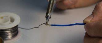
Many radio amateurs and home craftsmen are familiar with this heating device. It can be used to connect various parts made of ferrous and non-ferrous metals. Owners are often interested in the question: how to repair a soldering iron at home? The fact is that this tool can fail as a result of improper handling. Of course, you can take it to a workshop and have it done by a professional. However, many owners prefer to do it on their own.
How to fix a soldering iron? This is especially of interest to those who have just begun to master this heating device. In general, this task will not be difficult to cope with if you identify the cause of the breakdown and strictly adhere to a certain algorithm of actions. Information on how to repair a soldering iron at home is presented in this article.
Components of the tool
Before you are interested in how to repair a soldering iron at home, you should know how it works. In this case, if there is a breakdown, it will be easier for you to determine the cause and fix it. The soldering iron device is represented by the following elements:
- Copper rod. It is wrapped in insulating material and housed in a steel tube.
- Heater. This task is performed by nichrome thread.
- Sting. They use solder to directly connect metal parts.
- With a pen. Thanks to it, the master can hold the soldering iron.
- Cord equipped with a plug.
Description of design
The copper rod is an effective conductor of heat that flows from the heater to the tip. The rod is located in a steel tube wrapped in mica or glassy tissue. A wire is wound over the mica, which acts as a heating element. To prevent heat loss and short circuit, the nichrome winding is insulated, covered with asbestos for this purpose. The ends of the spiral are connected to the conductors of the power cord. To make the design more reliable and the connection point not to overheat from the heat generated, the nichrome spiral is bent in half and folded in half. Additionally, the point of contact of the spiral with the copper wire is crimped using an aluminum plate. In addition, the twisting area is covered with an insulating tube. All of the above elements are housed in a metal casing. It is mounted on a handle, which can be made of wood or thermoplastic. Inside the handle there is a special channel for the electrical cord. The housing is fixed to the metal tube using overlay rings. Those who are interested in how to repair a soldering iron at home should also know about the technical characteristics of the electrical appliance.
Soldering iron 60 W with temperature control 907 (GJ907)
In this review, we will look at one of the most inexpensive Chinese soldering irons with temperature control and replaceable tips: model 907 (GJ907) , 60 W. I’ll say right away that this soldering iron has nothing to do with the Hakko 907 soldering irons for soldering stations. Usually on AliExpress, eBay, Bangood and other Chinese trading platforms this product is called something like “907 60W soldering iron Adjustable 200-450C“. The cost of a soldering iron at the moment (June 2015) is about $10.
Specifications of GJ907 soldering iron:
- Power: 60W
- Temperature: 200.450°C
- Input voltage: 220. 240V
- Insulation resistance: 100MΩ
- Length: 240mm
The soldering iron is supplied in a transparent package with some information in Chinese.
The soldering iron tip can be grounded if necessary. And it is necessary! Because There is no decoupling from the mains voltage and interference can kill field-effect transistors, microcircuits and other sensitive elements when soldering. According to reviews on the Internet, such cases have happened. For grounding, a wire with a clamp comes out of the soldering iron.
The power plug, as you can see in the photo, is the most common one; no adapters are needed.
The soldering iron is equipped with a temperature regulator, which is adjustable from 200 to 450 ° C. If the LED is on, then the soldering iron is in the process of heating. Once the desired temperature is reached, the LED goes out. Judging by the diagram, it is thermocouple feedback that is used here, and not stupid power adjustment, which is an undoubted advantage of an inexpensive soldering iron.
The soldering iron tip is removable and non-burnable.
The tip is not compatible with the 900s. For comparison, in the photo below: the tip is 900 at the top, 907 at the bottom. They are different in both length and diameter.
Dimensions of 907 tips:
- External diameter: 7.5 mm
- Inner diameter: 6mm
- Depth: 35 mm
- Length:
56 mm (depending on the shape of the tip)
Dimensions 900 tips:
- External diameter: 5.4 mm
- Inner diameter: 4.2mm
- Depth: 24.5 mm
- Length:
42 mm (depending on the shape of the tip)
But 907 tips for it are also freely sold on AliExpress. Search for soldering iron tips GJ907 on AliExpress.
According to the manufacturer and many online resources, the GJ907 has a ceramic heater. In the photo below you can see a step, which, according to some radio amateurs, indicates that this is real ceramics. There is a lot of debate on the Internet about what type of heater this soldering iron has: ceramic or nichrome in a ceramic tube. We'll find out later.
The heater itself is labeled 907H 220V 60W and is freely sold on AliExpress for about $2.
There are 4 wires coming out of the heater: two wires for the temperature sensor and two wires for the heating element. On the one hand, the presence of a temperature sensor is a plus, but on the other hand, the fact that it is located in the heater itself is a minus, because There will be inertia and a delay in the activation of heating. The resistance of the heating element is 890 Ohms (two white wires). Thermal sensor resistance at room temperature (red and blue wire):
4 ohms. The voltage on the heating element is 220V.
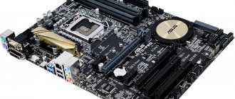
Control board. Operator IC2: HA17358 (LM358). A MAC97A8 triac is used to control the heating element (PDF)
The circuit is in many ways similar to the CT-96 soldering iron circuit:
As you probably already saw in the photo, this soldering iron has two trimmers VT1 and VT2. One sets the upper temperature range, the second sets the lower one.
As can be seen from the diagram, there are no scarce parts, SMD is also not used, and in case of failure, the burnt-out part can be replaced. In general, in terms of maintainability, the soldering iron is also quite good, because... and something can be replaced in the board, and the heater itself and the tips are freely sold on AliExpress.
Ceramic or nichrome?
Advantages of a ceramic heating element: - fast heating - durability Disadvantages: - fragile (and more often cracks from uneven heating and incorrect tips than from mechanical influences)
Advantages of a nichrome heating element: - cheap - not afraid of shocks or falls Disadvantages: - not very durable - takes longer to heat up
But if we objectively compare it for use in amateur radio practice or for domestic use, then of course a nichrome heating element will not heat up, say, 10 times longer than a ceramic one, and in practice you will not notice much of a difference in the heating rate. As for the service life, this is also a controversial issue, because in my opinion, this is relevant for repair shops, where they operate a soldering iron for several hours a day. And for an ordinary radio amateur, when used for one hour a day, a cheap soldering iron will most likely experience some other breakdown than the nichrome heater filament burning out. Therefore, if you are a radio amateur, then in any case the nichrome will not burn out in 1-2 years of use.
So what type of heating element is used in this soldering iron?
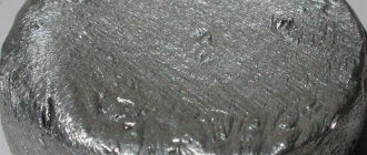
The photo speaks for itself. Those. It's a nichrome heater stuffed into a ceramic tube. In essence, we have a nichrome spiral, to which is added one of the disadvantages of ceramics - fragility. As you can see, the presence of a step at the end of the heater does not at all mean that this is ceramic!
Well, what else did you want for ten bucks?
Parameter measurements
So, let's measure the power consumption of the soldering iron.
As you can see, an honest 60 watts.
When the set temperature is reached, the heating is turned off, the LED goes out and the soldering iron consumes 600 mW.
The soldering iron tip was connected to a temperature meter (with a K-type sensor). Additionally, the readings were also checked using a thermocouple from a multimeter - no large deviations were found over the entire temperature range.
When set to 200°C (the lowest value), the actual temperature of the tip of the soldering iron was 250°C! Those. as much as 50°C more. I tried to set the lower threshold using adjusters, but the best I could achieve was 235°C, the temperature stubbornly refuses to go below this value.
When the value was set to 450°C, the actual temperature of the tip was about 415°C, i.e. the soldering iron did not reach 35° C. But such high temperatures, in principle, are not needed, because the sting will burn all the time. If you wish, you can play with the trimmer.
The time it took to raise the temperature from a cold soldering iron to the set temperature of 200 ° C (real 230-250 ° C) was just under a minute. At the same time, the inertia of the tip is about 3 seconds, i.e. From the moment the heating is turned on, until the temperature changes on the tip, about 3 seconds pass. The temperature meter itself reacts to temperature changes almost instantly.
conclusions
Cons: - pseudo-ceramic heater - temperature indicators do not correspond to real tip temperature readings - in my opinion, the handle is not very comfortable (maybe a matter of habit, especially after working with a soldering station) - according to reports from some users who have a similar soldering iron - not very reliable
Pros: - honest 60 watts - low cost - ability to adjust temperature - replaceable tips, freely sold on AliExpress - ability to replace the heater in case of failure (also freely sold on AliExpress)
Is it worth buying or not? If you are very limited in money, you can take a risk, but it’s still better to pay an extra $20-30 and take something more reliable.
How does the device work?
Those who do not know how to repair a soldering iron with their own hands should familiarize themselves with the principle of operation of an electrical device. The soldering iron functions by converting electricity into heat. As a result, heat is transferred through the heated spiral to the rod, as a result of which the tip becomes heated. You should know that in the area where soldering is carried out, the temperature varies from 400 to 4500 °C. As a result, a mixture of viscous-liquid consistency is formed. Subsequently, it fills the cavity between the parts being soldered. When the mixture cools, the metal parts are securely connected.
DISASSEMBLY AND REWINDING THE SOLDERING IRON
If you, a fellow hobbyist, have already “outgrown” a soldering iron with a voltage regulator, but have not yet “grown up” in your ambitions to a professional soldering station, then this might be interesting. The ability to change the supply voltage of a soldering iron designed for 220 V, among other things, allows you to return to operation an already burnt-out one. And use it in the future, for example, with a switching power supply from an imported TV, which at the output gives exactly half of the network one. Bringing these two products together results in an intermediate option between a soldering iron with a regulator and a full-fledged soldering station. Any radio amateur can do this. I’ll show you how to do this using the example of changing the supply voltage of a Chinese-made soldering iron, which was not trustworthy for use without modification.
About voltage
If there is a need to repair the device, take into account the voltage indicator. Depending on the model, its value may be:
- 220 V. This value is mainly found in domestic models.
- 12-42 V. Devices with a reduced voltage transformer are used in conditions with high levels of dust or humidity in order to protect the technician from electric shock.
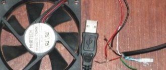
- 5 V. Miniature USB soldering irons have this indicator.
Winding calculation
Repairing a soldering iron in most cases comes down to a procedure that allows you to rewind a burnt nichrome winding. When replacing it, it is important to correctly select the thickness and diameter of the nichrome wire, as well as the number of turns in the spiral, which determines the generated thermal power.
When calculating and selecting the required wire diameter, we proceed from the resistance value of the soldering iron’s heating winding, which, in turn, is determined by its operating power (supply voltage).
To determine the initial indicator (winding resistance), special tables are used.
| 220 | 127 | 36 | 12 | |
| 35 | 1380 ± 10% | 460 ± 10% | 37 | 4,1 |
| 50 | 970 » | 320 » | 26 | 2,9 |
| 65 | 750 » | 245 » | 20 | 2,2 |
| 90 | 540 » | 180 » | 14,5 | 1,6 |
| 120 | 410 » | 135 » | 10,8 | — |
| 200 | 240 » | 80 » | 6,5 | — |
| 350 | — | — | 3,7 | — |
| 0,20 | 35,3 | 34,1 | ||
| 0,22 | 29,2 | 28,2 | ||
| 0,25 | 22,6 | 21,8 | ||
| 0,28 | 18,0 | 17,4 | ||
| 0,30 | 15,3 | 15,2 | ||
| 0,32 | 13,8 | 13,3 | ||
| 0,35 | 11,3 | ID | ||
| 0,40 | 8,59 | 8,52 | ||
| 0,45 | 6,98 | 6,73 | ||
| 0,50 | 5,66 | 5,45 | ||
| 0,60 | 4,07 | 3,82 | ||
| 0,70 | 2,91 | 2,84 | ||
| 0,80 | 2,23 | 2,17 | ||
| 0,90 | 1,76 | 1,72 | ||
| 1,00 | 1,42 | 1,39 |
| Table for determining the resistance of a nichrome spiral depending on the power and supply voltage of electrical devices , Ohm | ||||||
| Soldering iron power consumption, W | Soldering iron supply voltage, V | |||||
| 12 | 24 | 36 | 127 | 220 | ||
| 12 | 12 | 48,0 | 108 | 1344 | 4033 | |
| 24 | 6,0 | 24,0 | 54 | 672 | 2016 | |
| 36 | 4,0 | 16,0 | 36 | 448 | 1344 | |
| 42 | 3,4 | 13,7 | 31 | 384 | 1152 | |
| 60 | 2,4 | 9,6 | 22 | 269 | 806 | |
| 75 | 1.9 | 7.7 | 17 | 215 | 645 | |
| 100 | 1,4 | 5,7 | 13 | 161 | 484 | |
| 150 | 0,96 | 3,84 | 8,6 | 107 | 332 | |
| 200 | 0,72 | 2,88 | 6,5 | 80,6 | 242 | |
| 300 | 0,48 | 1,92 | 4,3 | 53,8 | 161 | |
| 400 | 0,36 | 1,44 | 3,2 | 40,3 | 121 | |
| 500 | 0,29 | 1,15 | 2,6 | 32,3 | 96,8 | |
| 700 | 0,21 | 0,83 | 1,85 | 23,0 | 69,1 | |
| 900 | 0,16 | 0,64 | 1,44 | 17,9 | 53,8 | |
| 1000 | 0,14 | 0,57 | 1,30 | 16,1 | 48,4 | |
| 1500 | 0,10 | 0,38 | 0,86 | 10,8 | 32,3 | |
| 2000 | 0,07 | 0,29 | 0,65 | 8,06 | 24,2 | |
| 2500 | 0,06 | 0,23 | 0,52 | 6,45 | 19,4 | |
| 3000 | 0,05 | 0,19 | 0,43 | 5,38 | 16,1 | |
| Table of dependence of linear resistance (one meter) of nichrome wire on diameter | |||||||||||||||||||||||
| Diameter of nichrome wire, mm | 0,05 | 0,07 | 0,08 | 0,1 | 0,2 | 0,3 | 0,4 | 0,5 | 0,60 | 0,7 | |||||||||||||
| Linear resistance, Ohm/m at 20°C | 550 | 280 | 208 | 137 | 34,6 | 15,7 | 8,75 | 5,60 | 3,93 | 2,89 | |||||||||||||
| Diameter of nichrome wire, mm | 0,8 | 0,9 | 1,0 | 1,2 | 1,3 | 1,5 | 2,0 | 2,2 | 2,5 | 3,0 |
| Linear resistance, Ohm/m at 20°C | 2,20 | 1,70 | 1,40 | 0,97 | 0,8 | 0,62 | 0,35 | 0,31 | 0,22 | 0,16 |
Using these tables, you can check the correctness of the winding calculations in order to carry out repairs in the future.
With a fixed supply voltage U and the resistance of the heating device R measured using a tester, the power P consumed by it is calculated using the formula P=(UxU)/R.
About power
This technical characteristic determines the functionality of the soldering iron. For example, for home use to work with wires, a power of 30 W will be sufficient. These soldering irons are mainly used by radio amateurs. Professional installers operate devices with power up to 60 W. Such devices are convenient for soldering wires and cables of various diameters. Soldering irons over 60 W are used in automobile workshops. These soldering irons are suitable for tinning large metal products. It is noteworthy that the higher the power indicator, the larger and heavier the device itself. With increasing power, the size of its tip (sting) also increases. Thus, a soldering iron with more power will heat up the soldering area better. What to do if your electric soldering iron breaks down? How to fix the device?
Detailing
The soldering iron handle was made from a jump rope handle. Unfortunately, the handle did not have a through hole, and it had to be drilled. The video shows how this can be done.
The sketch included self-tapping screws as fastening elements for fastening the case and cable, but I didn’t have such small screws at home. So I used hollow rivets that I cut threads into.
I glued the threaded bushings and a spring from a ballpoint pen obtained in this way with epoxy glue into the holes drilled in the pen. If you use self-tapping screws, it is advisable to also drill holes for them so that the handle does not crack.
The frame of the soldering iron is a small tube bent from tin from a tin can. A piece of copper wire with a diameter of 2.5 mm was used as a template for bending the tube. The same wire served as a blank for making a soldering iron tip. When using wire of a different diameter, you will have to make an amendment to the frame development drawing.
The body of the soldering iron is also made of 0.3mm thick tin from a tin can.
In order to ensure the correct shape of the holes and not remove burrs when drilling holes with a diameter of 3 and 4 millimeters, it is better to use drills with zapfenbor sharpening. The holes of the sizes indicated above are necessary to reduce the temperature of the body at the point of its connection with the soldering iron handle. The different diameters of these holes were chosen so that the bending line of the planks did not pass through the holes.
And this is a drawing of the developments: the body, the frame and the contactor. The drawing can be glued to the sheet metal and used as a template for cutting the outline and marking holes. Below the preview is a drawing in A4 format. Drawing scale 1:1, resolution 300 pixels per inch.
Repairing a burnt-out soldering iron. Where to begin?
Before you repair the soldering iron yourself, you should disassemble it. This is necessary in order to get to the heating element, namely the nichrome wire. For this purpose, unscrew the mounting bolts and disassemble the device. Overall you will only need to remove two bolts. When they are removed, take out the soldering iron “filling”, which is contained inside the metal case. To do this, you will have to carefully open the case itself. At this stage you must be very careful not to damage the thin and very fragile insulation. If handled carelessly, it may fall apart.
Restoring the heating element
When you get to the heating element, carefully inspect the nichrome wire. It may happen that several turns of wire are burnt out. To restore the heating element you need to do the following. Take an old broken soldering iron and remove a small piece of wire from it. Next, connect it and wind it instead of the burnt out turns. According to experts, when connected without adding wire, the spiral will burn out again due to reduced resistance. You need to wind it so that the turns do not touch each other. Then connect the power cord.
Why doesn't the soldering iron heat up? How to fix it?
Most often, the cause of this malfunction is poor contacts. First check the voltage supply. If it turns out that the current power is normal, then most likely the malfunction is caused by an incorrect location of the tip. This happens especially often in electrical appliances with retractable rods and screw terminals. Often the tip wears off or for some other reason ends up being too protruded from the body. If the working surface is located normally, then its end part in the form of a core is completely located in a mica tube. Thus, the contact of the rod with the heating element occurs fully, due to which the tip heats up more. If it is removed from the tube at least halfway, the heating intensity will decrease significantly. Repairing the device is easy. Home craftsmen insert the sting deeper into the body and fix it. It may be that the rod turns out to be too short. In this case, it is replaced. Also, the soldering iron may not work due to scale on the tip. It is removed, if necessary, and then the surface is cleaned using ordinary fine-grained sandpaper or a needle file.
The sting is then heated and dipped in rosin, after which its tip is rubbed on a braid with solder. As a result of such actions, the rod will be covered with an even layer of solder. Experts recommend performing this procedure more often with soldering irons equipped with copper rods, since scale forms on them faster. Also, the soldering iron may not heat up due to improper sharpening of the tip. For effective heat transfer, the working surface must have the shape of an oval bevel.
Soldering iron assembly
The heating element spiral is wound on a tin frame. Between the frame and the spiral there is a mica (or glass fiber) gasket. To prevent the mica plate from falling apart when winding the spiral, it was glued to a piece of fiberglass. On the outside, the spiral is also insulated with several layers of fiberglass.
The terminals of the spiral are covered with a fiberglass tube, borrowed from an electric stove discarded by neighbors.
To ensure uniform clamping of the heater by the tin shell, a small tin contact is inserted into the gap in the shell. It prevents the glass fabric from being squeezed into the shell gap.
And this is a homemade soldering iron for soldering assembled SMD parts. The small distance between the front edge of the handle and the end of the tip ensures the necessary accuracy of tip positioning when installing small radio components.
About using solder
If you notice that your tool heats up weakly, then most likely you have chosen the wrong solder. For example, for low-power electrical appliances rated at 26 watts, it is not recommended to use low-tin solder (POS-30). You will not melt this solder with this soldering iron. It is best to get POS-60 or POS-61 solder. Other solders with a high lead content are suitable for higher power electrical appliances.
How to repair an electric soldering iron
An electric soldering iron is a well-known heating device designed for joining a wide variety of parts made of non-ferrous or ferrous metals.
The operating principle of the tool is based on the heating effect of its working tip (tip), which melts the solder with flux. The resulting liquid mixture fills all the unevenness and voids between the parts and forms a reliable connection after cooling.
But during operation, the tool can break, and such damage manifests itself in a variety of forms. That is why independent repair of a soldering iron is a mandatory operation that any master working with it must master.
About rewinding an electrical appliance
Beginners often ask the question: how to rewind a soldering iron? Judging by numerous reviews, very often device repair is limited to replacing the burnt nichrome winding. Before starting this procedure, use a special table to calculate the diameter of the wire, as well as the number of turns. For example, how to repair a 200W soldering iron? To do this, select the soldering iron power consumption indicator of 200 W (in the left column of the table). To this value, the winding resistance at a voltage of 220 V will be 242 Ohms. It will be best to rewind the entire reel.
In this case, there will be no weak points in the device. It is very important that the new wire has the same parameters as the old winding. If it is not possible to select a similar insulating layer, then it can be replaced with mica in the form of a tube or plates. You can also use heat-resistant fiberglass or asbestos gaskets to make an insulating layer. After the insulation is ready, wind the winding (first layer) around it. Next, put another layer of insulation on the turns and wind the winding again (second layer). Now all that remains is to connect the ends of the wire to the power cord.
Wire annealing technology
And so, I will describe the procedure for firing varnished wire. Here we can add that nichrome, constantan or manganin wire is suitable for the soldering iron heater.
If you don’t have a continuously variable DC source, you can use this simple device to anneal a thin wire. A wire is attached to two weights, and a spring is attached to the third, which maintains tension on the wire.
The stronger the tension of the wire and the shorter the spans, the smaller the amplitude of parasitic vibration that occurs under the influence of alternating current. The fact is that the vibrating sections of the wire are better cooled by air, which leads to uneven heating of the wire.
If the thin wire is also varnished, then you need to increase the voltage very carefully. This process is described in more detail in the video illustration.
Return to top to “Table of Contents”
Broken wiring
How to fix a soldering iron with your own hands if the electrical cord is faulty? Judging by numerous reviews, this reason for device failure is considered the most common. You can correct the situation on your own. Many owners simply replace the plug or cord. Of course, it all depends on which part the break occurred in. This defect is correctable, and you can fix it yourself. To determine exactly where the break occurred, you will need to acquire a special device, namely a multimeter. Use the probes of this device to examine the wiring. In the place where the break occurred, you need to reconnect the wires and insulate them.
Verification schemes
Checking the soldering iron heater
This means that the soldering iron is working. Also, by analogy with heating elements, if the soldering iron heater does not ring at the limit of 20 kiloohms, most likely the soldering iron has burned out. It would not be superfluous to check at the limit of 2 megaohms between the body of the soldering iron and the pins of the plug alternately. Also, if there are numbers other than one, then this soldering iron cannot be used.
Heater Insulation Check
An iron (without electronics) is checked in the same way, which for some reason does not heat up. We check it in a way that is already known to us, by touching the probes of the multimeter in ohmmeter mode, setting it to a limit of 200 ohms on the pins of the iron plug. Why 200 Ohms, our iron load is quite powerful, and the more powerful the load, the less resistance its heater has. If the multimeter screen shows one, which means the heater does not ring, you will need to disassemble the iron in order to further diagnose the malfunction. True, it would not be amiss to turn the iron regulator before this; in the extreme position of the regulator at the minimum temperature, the iron turns off and the heater will not ring. If the iron heater does not ring at any position of the regulator, you need to remove the iron cover and ring the iron cord.
Read also: How to turn on the sound on the Starline A91 key fob
Continuity of supply wires
Very often, a device that has been in use for a long time and has been frequently used has a break in one of the cord wires. To do this, switching the multimeter to the audio test mode, touch one pin of the plug and the cord connected to the iron. If the sound signal does not sound, touch the probe to another wire of the cord connected to the iron. If both wires of the cord are intact and in both cases a sound signal is heard, we proceed to testing the heater itself, also in ohmmeter mode at a limit of 200 Ohms.
Low power power cord
If the cause of the breakdown is the cord, we replace the cord with a similar one, always (!) taking into account the power of the device. That is, for an iron or electric kettle you cannot use a cord with small cross-section wires, used to power, for example, a tape recorder. Such a wire will soon melt and fail.
Power cord designed for high power
Breakdowns also often occur in equipment power switches. If, for example, there is a table lamp with a power switch that “sticks” or turns on every once in a while, or the device has stopped turning on altogether, such a switch also needs to be checked and ringed with a multimeter in the audio test mode. To do this, install one multimeter probe on one terminal of the switch, the second probe on the other and click the switch.
In one of the two positions the tester beep should sound. To be completely sure that the switch is working, you can click it, ringing; when the switch is closed, there will be a sound signal, but when it opens, there will be no sound. This is done to check the mechanics of the switch. Sometimes the contacts of such switches burn out, in this case, if the switch is an open type, you can wipe the contacts with a cotton swab and alcohol, or if the soot is strong, carefully clean them with a knife.
In the same way, setting the multimeter to the audio continuity mode, check any fuses (fuse links) by touching both terminals with probes. If at the same time a sound signal is heard, then the fuse is intact and can be installed in the device; if there is no sound signal, then the fuse is blown. Of course, fuses should not be replaced with the first ones available, but only with ones designed for the same current.
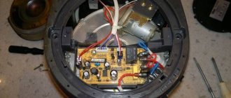
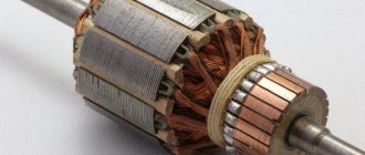
Electric DC motor
There may be a need to check the motor before turning it on, for example, like the one shown in the photo above; such motors are found, for example, in household hair dryers. The winding of such a motor can be tested with a multimeter in ohmmeter mode, setting it to a limit of 200 Ohms. In principle, in this way you can ring the winding of any motor by connecting the probes of a multimeter to the beginning and end of the winding.
How to fix a soldering iron with a regulator yourself?
Such electrical devices are equipped with a special device for adjusting the temperature of the tip. Using this soldering iron is quite convenient. The master knows that it is heating up thanks to the LED, which glows while the tip is heating. When the working surface reaches the desired temperature, the LED will go out, after which you can begin soldering. According to reviews from owners of such soldering irons, these power tools often fail. For example, there are times when buttons come off or an LED does not light up. Some home craftsmen wrap buttons with insulating tape. To repair the device, you must first carefully disassemble it. When you do this, you will see the op amp. It is a microcircuit in which, most likely, one of the small batteries has become disconnected. It needs to be reattached. For this purpose, you first need to clean the “legs” of the battery, tin them, and then solder them in their original place. After completing these steps, the soldering iron can be assembled and tested.
Operating rules
When working with an electric soldering iron, in order to avoid accidental breakdowns of individual parts, you must adhere to the following rules:
- During soldering, avoid strong mechanical stress on the cord and the electric heater of the device.
- Do not overheat the soldering iron coil (do not leave it on for a long time).
- It is necessary to use a power regulator that allows you to select the required mode for heating the tip.
In conclusion, we note that during operation it is necessary to monitor the condition of the power cord and prevent it from being accidentally damaged by contact with a tip heated to a high temperature.
If this cannot be avoided, you should carefully isolate the melted area by placing a cambric over the damaged core and wrapping it with electrical tape.
A simple repair will help get your soldering iron working again. In general, thanks to its simple design, this tool rarely fails.
In this article we will look at and learn how to find and fix simple breakdowns in electrical devices. As everyone knows, the load can be either active, which includes all kinds of heating elements, or inductive, such as motors. Both can be checked using a continuity test with a multimeter, setting it in ohmmeter mode to a limit of 200 Ohm - 2 kOhm, sometimes you may need to select a limit of 20 kOhm, for a low-power load, such as a 25 Watt soldering iron.