At any facility, both industrial and civil, there are energy consumers for whom uninterrupted power supply is important. Along with this, there are electrical appliances, the temporary shutdown of which is not significant. A load priority relay (LPR) is precisely the device that, in the event of an overload in the electrical network, “selects” which consumers should be excluded and which ones should retain the supply of electricity.
Priority relay ABB LS1/2:
Types of relays
A priority relay, which divides networks into priority and less important ones, allows you to prevent the occurrence of malfunctions during network overloads in an individual home or small enterprise.
The use of an on-load tap-changer allows you to turn off less important devices when there is an overload in the network
Several types of on-load tap-changers are produced:
- 1- and 3-phase;
- single and multi-channel.
Three-phase devices are also capable of performing the function of phase priority, transferring the load through single-phase channels, preventing asymmetry leading to a complete shutdown of the entire facility.
Multi-channel on-load tap-changers can be used together with different lines.
According to their functional design, devices are divided into relays:
- lower threshold;
- upper threshold.
The high threshold relay is activated when the current increases and is connected in a series connection. A device that operates at a minimum voltage threshold, on the contrary, is connected to the network in a parallel circuit.
Relays are also available that are designed for different switching levels, which can be adjusted for different loads if necessary. In networks with heavy loads, the on-load tap-changer should be combined with a current transformer.
on-load tap-changer
Telephone relay with flat core type on-load tap-
changer
DC relays with a flat core of the on-load tap-changer type ( Relay Flat Normal ) are used in automation, telemechanics and communications equipment. The on-load tap-changer is intended for use only in stationary installations, as it is sensitive to deviations from the vertical and to external shocks.
Developer: The on-load tap-changer relay was presumably developed between 1945 and 1947 at the Krasnaya Zarya plant. The domestic on-load tap-changer relay was copied from the telephone flat-plate relay of the German company Siemens & Halske (Siemens and Halske), the production of which was launched in 1927 . Manufacturers: on-load tap-changer relays, apparently, were the most widely produced telephone relays; of the well-known manufacturers they were produced by: (KZ); Scientific and Production Association "Northern Zarya" (NW); Novgorod Production Association "Start"; Kharkov relay plant; Anthracite Relay Plant; Plant named after Maslennikov (ZIM); Riga State Electrotechnical Institute. Belgorod telephone plant Sokol There are also on-load tap-changer relays produced in Bulgaria (letters BDS) and the German (once German Democratic Republic) company Rundfunk-und Fernmelde-Technik (RFT) (Association of Radio and Telephone Equipment Manufacturers). On-load tap-changer relays were produced according to technical specifications NI0.450.000 TU and were discontinued in 19...
Equipment (equipment) in which the relay was used
ATS-47, ZHATS-48, PBX-49, ATS-54, PBX-50/100, ATSK-50/200, UPATS-100/400, ATS-VRS, ATS-10/40 and many other PBXs and switches.
Design and principle of operation
The on-load tap-changer relay is simple in design, almost all of its parts are stamped. The relay magnetic system consists of a stamped rectangular core, integral with the base, and a flat U-shaped armature, located parallel to the core and encircling the coil. The armature is pressed against the base of the relay by a flat spring and rests on a special support square (stop) fixed under the connecting group. The relay core and armature are made of soft, annealed electrical steel grade EA. To protect against corrosion, the relay core and armature are plated with nickel. Two rectangular cheeks made of getinax are mounted on the relay core, forming a frame (coil) for the relay winding. The front cheek of the coil also serves as a support for the relay contact springs. On the opposite side of the coil, a connecting group is attached to the base, containing five output springs for soldering the ends (leads) of the relay windings. The relay winding is insulated from the core with LSh-1 silk varnish or thick varnished paper. For relay windings, red copper wire with enamel insulation of the PEL brand with a diameter of 0.05 to 1.0 mm is used, but the most commonly used wire is with a diameter of 0.08 to 0.35 mm.
Figure 1. Design of telephone relay type RPN 1 – winding output; 2 – base; 3 – coil with windings; 4 – anchor; 5 – core; 6 – contacts; 7 – contact springs; 8 – package tie bolts; 9 – output of contact springs (contacts).
The contact system of an on-load tap-changer relay consists of one, two or three contact groups assembled into one common package, tightened with two screws. The places in the package where the contact groups are located are designated with Roman numerals from 1 to 5 (I, II, III, IV, V) and counted from right to left. The contact groups are placed in the package on the I, III, V places (rows) simultaneously (for an on-load tap-changer relay with three contact groups) or on the I and V places simultaneously (for an on-load tap-changer relay with two contact groups), as well as only on the third place (for on-load tap-changer relay with one contact group). In places II and IV, contact groups are not installed due to the fact that when contact groups are placed in these places, they will be located close to neighboring groups and there will be no possibility for full adjustment of the contact springs. Each group can contain from two to six contact springs. The contact springs have a width of 3.5 mm and a design (useful) length of 74 mm. They are made from especially hard nickel silver, grade MNTs15 - 20, 0.5 mm thick. The contact springs are insulated from each other by 1.0 mm thick getinax gaskets. The ends of the springs are forked and equipped with hemispherical contacts (diameter 2 mm). There are also contacts in the form of cylinders. Typically, the contacts of the on-load tap-changer relay were made of silver grade Ср 999; they can also be made of palladium grade Пд 998. The relay contacts controlling the finder circuits (1 A - 60 V) were made of platinum grade Пл 998 or an alloy of platinum with iridium ПлИ. In the diagram and drawings, the contact springs of the on-load tap-changer relay are designated by a two-digit number. The first digit in the number indicates membership in the contact group, the second digit in the number indicates the number of the contact spring in this group. The contact springs in the group are counted from bottom to top. From the above it follows that the contact springs of the I contact group will be designated 11, 12, 13, 14, 15, 16, the contact springs of the III contact group will be designated 31, 32, 33, 34, 35, 36 and, accordingly, the contact springs of the V contact the groups will be designated 51, 52, 53, 54, 55, 56.
Figure 2. Location and numbering of contact groups, contact springs and winding terminals of an on-load tap-changer telephone relay 1 – relay base; 2 – winding outputs and their numbering; 3 – contact springs and their numbering; 4 – numbering of contact groups
The transmission of forces from the armature to the contact springs is carried out using a moving getinaks plate (stop), mounted on a brass bridge, which is screwed to the armature with two screws. These screws also serve to secure the release plate, which prevents the armature from sticking. The bridge has a special protrusion that rests on the relay core and serves to adjust and limit the armature stroke. One of the disadvantages of the relay is the unbalanced and heavy armature (weight including bridge 34 g), which has a low natural frequency. In the normal position of the relay, the plane of the armature (and contact springs) should be located vertically to avoid the influence of the weight of the armature on the sensitivity of the relay and to reduce dust on the contact surface. The relay is attached to the board with one screw (diameter 4 mm); its body is not isolated from the board. Slow-motion relays of the on-load tap-changer type have on the core (under the working winding) a short-circuited winding made of bare copper wire with a diameter of 0.5 mm. Depending on the degree of deceleration, the short-circuited winding has a height of 1.2 or 3 mm (2, 4 or 6 layers of wire). At the ends of the delayed relay cores, the corresponding designations are made: K1, K2 and KZ. Accordingly, on-load tap-changer relays of various modifications can be single-winding, two-winding, three-winding, four-winding, five-winding, with improved and normal residual magnetization and additional resistance in the form of an additional winding. The contact system of the on-load tap-changer relay, depending on the passport, can consist of various combinations of contacts (contact springs); in order to understand what action a particular contact spring is intended for, numbers are applied to them. Below is a breakdown of the contact spring numbers. 01 - Close 02 - Open 03 - Switch 04 - Close three contacts in series 05 - Open three contacts 07 - Make and open 10 - Two open 11 - Switch from 2nd to 4th contact and open 1st and 2nd contacts 12 - Opening the 3rd and 4th contacts and switching from the 1st to the 3rd contact 18 - Switching from the 2nd to 4th contact and closing the 1st and 2nd contacts 26 - Two short circuits in series 27 - Opening and closing in series 28 - Opening and closing in series 29 - Opening and closing of three contacts in series 46 - Two short circuits 81 - Short circuit (special contact group) 95 - Transient switching 100 - Opening and switching 102 - Short circuit and switching 103 - Short circuit of two and three contacts 105 - Transient switching and closing 106 - Transient switching and opening Explanation of the relay designations on the label As was already written above, the type of on-load tap-changer relay stands for Flat Normal Relay the label, the type designation appears only at Rizhsky. From the type you can understand that this is an ordinary flat-type electromagnetic relay, that is, with a flat core. The label of the on-load tap-changer relay typically indicated information about the quantity, number of turns, winding resistance and numbers of their terminals, as well as the brand and cross-section of the wire with which they were wound. In addition to information about the windings, the logo (trademark) of the manufacturer and the passport of the coil and the relay itself were applied to the relay. On on-load tap-changer relays manufactured closer to the 90s of the last 20th century there is information about the material from which the relay contacts are made and their weight. An example of decoding a label from an on-load tap-changer relay is shown in Figure 3.
Figure 3. Label from on-load tap-changer relay
1 – Relay winding data. From the designation it is clear that the relay coil contains 3 windings: - the designation of the first winding “1-2-1000-8400-0.09-PEL” is deciphered as follows - 1 terminal of the beginning of the winding, 2 terminal of the end of the winding, winding resistance 1000 Ohms, winding contains 8400 turns of wire with a cross section of 0.09 mm PEL grade; — the designation of the second winding “3-4-1000-8400-0.09-PEL” is deciphered as follows: 3 terminal of the beginning of the winding, 4 terminal of the end of the winding, winding resistance 1000 Ohms, winding contains 8400 turns of wire with a cross-section of 0.09 mm of the PEL brand ; — the designation of the third winding “1-5-350-3150-0.11-PEL” is deciphered as follows: 1 terminal of the beginning of the winding, 5 terminal of the end of the winding, winding resistance 350 Ohms, the winding contains 3150 turns of wire with a cross-section of 0.11 mm, grade PEL . 2 – Data sheet of the relay coil “RS3.259.003 Sp 122”. At the same time Sp does not stand for “palladium or platinum content”; it is a document code, and the letters are an abbreviation for the words “Consolidated Specification”. 3 – Logo (trademark) of the relay manufacturer. In this particular case, the SZ logo belongs to the NPO Severnaya Zarya. 4 – Relay passport “RS4.535.076D”. By the first two letters contained in the passport, you can recognize the company that produced the relay or developed design documentation for it. In this particular case, the letters “RS” mean that the documentation for this relay was developed in . The numbers following the letters “4.535” are the decimal (decimal) characteristics of the relay, according to [7] - this is a direct current electromagnetic relay. The following decimal characteristics are also found on the on-load tap-changer relay: 4.500, 4.503, 4.505, 4.513, 4.530, 4.533, 4.535, 4.552, 4.553 and others. The numbers “076” after the decimal characteristic are the serial registration number of the relay modification. What the final letter “D” means is still unknown to me. 5 – Brand and weight of non-ferrous metal contained in the relay contacts “Avg. 999-0.2509 g”. Everything is clear here, the contact material is silver, the weight of which is 0.2509 grams.
And for those interested in non-ferrous metals, on a separate page [6] I published information on the passports of on-load tap-changer relays, which have a more noble metal in the contacts than silver.
Brief technical specifications
Input parameters: Rated winding voltage: 60 V DC Operating current: depending on the passport Output parameters: Current switched by contacts: 0.03 - 2 A Rated contact voltage: 1.5 - 120 V Dimensions: 35 x 26 x 108 mm ( H x W x D) Weight: no more than 0.24 kg
Additional information (sources of information)
1. Calculation of electromagnetic relays for automation and communication equipment. M.I. Vitemberg M-L.: Energy, 1966. 1-4. Flat core type on-load tap-changer relay. A description of the relay is given (DjVu, 73 kB.) 2. A reference book on the elements of automation and telemechanics. Time relays, program devices, counting relays, finders. 1960 edition. On-load tap-changer relay. Passport numbers of different economic councils, old and new. (DjVu, 790 kB.) 3. Instructions for adjusting on-load tap-changer relays, 1950 4. Telephone relays. Their design and calculation. G.P. Matov. L.-M.: Gosenergoizdat, 1934 5. Calculation of telephone and code relays. M.I. Witenberg. L.-M.: Gosenergoizdat, 1947 6. Information on passports of telephone on-load tap-changer relays containing platinum, palladium, tungsten, etc. >> watch 7. Interdepartmental normal. Drawing management system. Part IV. Designation of design documents. N0.00.005. Revision 2-60.
Design
Thanks to the current meter and actuator in the relay, when the current reaches the set value, the contacts are switched. The meter detects current strength in the configured range, and also, depending on the characteristics of consumers, can be configured for switching.
For standard contacts, the maximum switched current is 16A. At enterprises, there is a need to switch larger currents, therefore there is a need to use special contactors.
If magnetic contactors are used, the on-load tap-changer is a separate design and transmits a control signal to the conductor, that is, it does not have the ability to independently switch contacts.
Specifications
When choosing this mechanism, it is recommended to pay attention to the main technical characteristics. These include:
Another model looks like this
- highest switching current;
- number of contacts;
- response time delay;
- the value of the highest current characteristic of the non-priority group;
- temperature at which the device remains operational.
Indicates: supply voltage; maximum switching power; controlled current interval; the value of the threshold value from the maximum current value.
The warranty period, mechanical and electrical wear resistance, dimensions and installation methods are also indicated.
Device operation
The relay design has a current transformer capable of measuring the current of all connected electrical appliances. If the current threshold is exceeded, the first contact operates and the first non-priority load is switched off. At the same time, the red indicator L1 lights up, indicating this shutdown.
If after disconnection the total value of the current load has not changed, then the second non-priority group of contacts is switched off. At the same time, the L2 indicator starts to light.
After this, the relay attempts to reconnect at intervals of five minutes. Switching on is done in the reverse order. First, the second non-priority group is turned on, and then the first, provided that the current has returned to its original value.
Application area
Considered the most essential power line, it must be connected at all times. Non-priority lines are those whose disconnection from the network in case of overload will not lead to any consequences.
In case of overloads, lighting important for the safety of the enterprise will not be switched off, but only consumers on the line with low priority will be switched off. When normal network operation is restored, all non-priority consumers will automatically connect.
If an overload occurs due to the switching on of several devices, it is possible to turn off only one of them. At the same time, power supply to high-priority consumers will be restored.
Our objects
We provide services for the design of engineering systems, development of design and estimate documentation. We carry out construction, installation, commissioning, as well as further maintenance.
"Administrative and household complex" LLC "Gazprom dobycha Noyabrsk" in Noyabrsk
Center for spiritual and moral development in Noyabrsk
Museum of the History of Gazprom Dobycha Urengoy LLC in Novy Urengoy
"Sports and fitness complex" in Novy Urengoy
Administrative complex "Gazprom Dobycha Yamburg" in Novy Urengoy
Administrative building of Gazprom Dobycha Urengoy in Novy Urengoy
Sibneftegaz office building in Novy Urengoy
GAZPROMBANK in Novy Urengoy
Operating principle and installation of on-load tap-changer
A current transformer is connected to the common line, and after it - consumers. The first stage of the circuit includes loads that have priority and cannot be switched off.
Then a consumer relay is included in the circuit, through which non-priority load groups are connected. If the current in the network exceeds, they will be switched off in a set sequence in accordance with the degree of importance.
The signal coming from the current meter is sent for analysis to the comparator built into the module. This element correlates the signal with the main voltage value set according to the settings. The relay determines the moment when the comparator operates and the time to turn off low-priority loads. The result is a decrease in current in the network. After the time set in the device settings, the relay will try to connect less important consumers to the network.
Multi-channel on-load tap-changers are capable of simultaneously working with several lines that are switched off sequentially, starting with the lowest priority. The lines are turned on, on the contrary, starting from a higher level of significance.
Installing a relay allows you to get by with a standard set of equipment without the cost of additional network power. This allows you to save money - this is especially noticeable on the scale of even a small enterprise.
Below is a connection diagram using an example of an apartment. At the entrance there is a switch (25A), then a counter and a group of automatic machines. A certain number of household appliances of various types and power are also connected.
Typical diagram for connecting the on-load tap-changer to the network in an apartment in a multi-storey residential building
If it is necessary to simultaneously turn on all electrical consumers at once, the output circuit breaker in the panel will turn off, the light will go out and all devices will stop functioning. The thermal blocking will be activated and the machine will cut off the power supply to the entire apartment. It will be necessary to find the reasons that led to the overload and restart the machine.
Tip No. 1: When using an on-load tap-changer, such a problem and the difficulties associated with it can be avoided. It is necessary to prioritize those lines that are required first, and classify minor loads as non-priority. The device will limit the flow of electric current from the network and will not allow a complete shutdown.
Such devices are widely used in protection systems at enterprises of any size to prevent the occurrence of emergencies and emergency situations. The use of on-load tap changers is especially important in industries with a large number of machines and technological equipment, where overloads, short circuits or power outages can lead to serious consequences.
Device structure
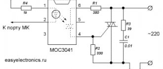
The width of the on-load tap-changer takes the place of 5 RCDs on the DIN rail. On the facade of the device you can see a peculiar pattern reminiscent of a stylized web. This is a primitive image of the device connection diagram. A more understandable layout for connecting one priority line and two non-priority directions is drawn next to it. Below is a detailed electrical diagram for constructing overload protection in a home network.
Detailed on-load tap-changer connection diagram:
The priority load relay has a built-in current meter (transformer + executive switch), which regulates the switching of contacts in non-priority directions when the threshold load limit is exceeded. As a rule, it has a standard value of 16 A. The relay is serviced by a fairly large number of radio components on several boards, as can be seen in the two lower photos.
Internal structure of on-load tap-changer:
ABB LSS1/2 backplate:
Since 2022, the Swiss company ABB (4 branches operate in Russia) began producing new ABB LSR priority selection relays. The new device is designed for a direct current of 32 A and a maximum power of 7 kW. The company’s specialists considered a relay in demand that would determine non-priority on inputs with a current of 16, 20, 25 and 32 A.
ABB LSR on-load tap-changer:
Using the display and control keys, the relays are configured through the menu, controlling the contactors. The output contacts are connected directly to the power source. They can switch any load lines. The current strength in digital terms is displayed on the screen in any part of the home's electrical network.
A limited current power limit due to the small cross-section of wires in hidden electrical wiring, considerations of saving energy consumption, or restrictions of the local electric company, causes a lot of inconvenience to its customers. In any case, installing a priority selection relay will significantly increase the comfort of living in an apartment or house, and will prevent unexpected shutdowns of all electrical appliances at the same time.
Examples of connection diagrams
Let's look at single- and three-phase connection diagrams using the ABB LSS 1/2 device as an example.
ABB LSS 1/2 relays are among the affordable and high-quality devices on the market in our country
According to the scheme for a single-phase system, a 25-amp meter is installed first, followed by an automatic meter. Then a relay is installed that controls the voltage, but to simplify the picture it is not shown in the diagram. The following shows a relay for controlling a load with a phase connected to it (in this case, the system is single-phase), which inside the relay is divided into three lines:
- PL - priority line;
- NPL1 - first line non-priority;
- NPL2 - second line without priority.
An example of dividing loads in accordance with their priority through an on-load tap-changer.
Devices are connected to the lines through automatic machines (with a rating not exceeding 16A). When connecting machines of higher power, they need to be connected via contactors (second circuit). If the total load exceeds the permissible load, the relay will turn off all loads, leaving only the priority one connected.
On-load tap-changer connection diagram for one phase, on the right - via contactors
L 1 AND L are disconnected first , the connection is made in the reverse order.
Tip No. 2: On-load tap changers also have a number of additional functions. For example, a forced shutdown switch for low-priority loads or a remote warning system for line outages.
A three-phase connection diagram, the operating principle of which is identical to a single-phase diagram, for the ABB LSS 1/2 device is shown in the figure below.
Connection diagram for ABB LSS 1/2 relay for three phases
Priority relay. Automatic load control
Greetings, regular readers and guests of the site!
In this article, we will take a closer look at the purpose and circuit of a priority relay, also called a load control relay or power limiter.
Today our life is unthinkable without a huge number of different household appliances. These assistants have become a part of our lives and help us solve our daily affairs. Washing machines, boilers, air conditioners, hobs, electric ovens, microwaves, audio and video equipment, many other devices - it’s hard to imagine a modern apartment without them.
But along with convenience and comfort, they significantly increase the load on our household electrical network. If you have a modern apartment, built taking into account new energy consumption requirements, then most likely you will not feel any discomfort. You simply enjoy the benefits of modern progress, have fun and don’t think about anything.
But what about those who live in old housing stock, where the wiring was laid back in Soviet times, according to old standards, when the main consumers were a TV, an iron, a table lamp and several light ? Indeed, in most of these apartments, the power per apartment is limited by the input circuit breaker at 25A. And if you connect several powerful modern electrical appliances at the same time, then it will simply “knock out” constantly; you will have to constantly run out onto the landing to the floor electrical panel and turn on this switched off circuit breaker.
Let's look at a typical wiring diagram for such an apartment.
A 25A input circuit breaker is installed at the input, limiting the power supplied to the apartment, followed by an electric energy meter, and then group circuit breakers.
Let's assume that we have made repairs and completely replaced the electrical wiring in the apartment with a new one, divided it into several groups, and connected powerful stationary consumers through separate lines. A boiler heats our water, air conditioners in the rooms create a comfortable microclimate, a washing machine washes clothes, we have a separate group for kitchen appliances, the sockets in the rooms are placed on a separate machine, the lighting is done in a separate group. Everything is modern and practical!
At the same time, if we turn on the washing, the boiler will heat the water for us, the air conditioner will cool the room, and in the evening, with the chandelier on, we will lie on the sofa and watch TV, then after a while the input machine in the floor electrical panel will “knock out”, the apartment will become dark and almost all the benefits of civilization will be inaccessible. I have already discussed a similar situation in detail in the article: the denominations of group machines exceed the denomination of the input one .
As a result of the overload, the thermal protection of the circuit breaker will trip and it will trip, limiting the power consumption. This is a typical case, since the input power to the apartment is limited and the simultaneous connection of powerful consumers will lead to constant activation of thermal protection .
In order to somehow cope with this situation, you will have to control the number of simultaneously connected devices, control them and their power, and not turn on several powerful consumers at the same time.
In order to cope with this situation and not get confused about what and what power we have connected at the same time, special load control relays were created - priority relays (they are also called power limiters).
ABB LSS1/2 load control relay as an example . The relay is designed for installation on a DIN rail and, when installed, occupies 5 modules. Such a relay after the input circuit breaker before the load and has two non-priority groups. The relay constantly monitors the current flowing through it (and, accordingly, the power consumed by the load), and if the current consumed exceeds the set value, the relay turns off the first non-priority group; if this was not enough, then the second non-priority group is turned off. Only the loads in a non-disconnectable group remain connected.
The setting at which the non-priority group is disabled is set using the switches on the left front panel.
Inside the priority relay contains a current transformer that measures the total current flowing through it from all consumers connected to the home electrical wiring.
If the threshold value is exceeded, the first contact is activated, disconnecting the first non-priority load. In this case, the red LED L1 lights up, which indicates that the first non-priority group is disabled.
If the total load current has not decreased below the threshold value, the second contact is triggered and the second non-priority group is turned off. Indication is carried out by the illumination of the red LED L2.
A reconnection attempt occurs approximately every 5 minutes. If the current in the circuit has decreased, then the second non-priority group is connected first, and if the current does not exceed the setting, the first non-priority group is connected.
The priority relay contacts are designed for a maximum current of 16A, so contactors are used to control non-priority groups. Power is supplied to the contactor windings through the priority relay contacts, and the power contacts of the contactors control the connection of non-priority groups to the power supply network.
In the example under consideration, the electrical wiring is divided into one non-switchable group (washing machine, room sockets and lighting) and two non-priority groups that can be switched off using a relay.
For detailed purpose, connection diagram and operating principle of the load control relay, see the video:
Priority relay.
Automatic load control Recommend
Model overview
The table shows the most popular relay brands among domestic buyers, indicating the main characteristics and estimated cost.
The choice of one model or another is determined not so much by the price as by the operating conditions of the relay and its connection diagram.
| Brand | Main characteristics | Approximate cost, rub. |
| ABB LSS1/2 | Voltage - 230 V ∼ ± 20% Highest priority load current 90 A Current range, A 5…90 Settable current ranges, A 5…30, 10…60, 15…90 | 2000 |
| Legrand 0 038 11 | Currents of low-priority loads - up to 15A Shutdown threshold, 15 - 20 - 25 - 30 - 40 - 50 - 60A The total current of connected consumers is 90A Number of modules - 5 | 1800 |
| CDS Schneider Electric | Current range: configurable priority channel from 5 to 90 A, low priority channels - 15 A. Voltage range: 240 VA +5%, -10% Frequency: 50/60 Hz. | 2200 |
| F&F PR-612 | Maximum priority load current - 16 A Maximum non-priority load current 15 A Low-priority circuit shutdown current adjustment interval 2 - 15 A | 1900 |
| Z–LAR/8 | Rated voltage 250 V Switching current >3 A Tripping current < 1.8 A Switching frequency - up to 3600/h | 1750 |
Disadvantages of using on-load tap changers and its analogues
Despite the large number of advantages associated with connecting and using load priority relays, using the device also has some disadvantages:
- To install a device into an existing network, it is necessary to perform a large amount of work related to upgrading the wiring and panel. To do this, it is necessary to invite a qualified specialist who will make an accurate calculation of the circuit in accordance with the load from all existing consumers.
- To lay separate cable lines from the switchboard to sockets with various consumers, it is necessary to wall groove and repair the premises.
- On-load tap changers are not installed on regular wiring, the design of which does not provide for the presence of separate lines to sockets.
Dividing lines into priority ones in everyday life has become easier thanks to the introduction of a new device - a network load optimizer, which also turns off non-priority electrical appliances.
The operating principle of the optimizer is to redistribute the power of consumers in accordance with their degree of importance. While the priority electrical appliance is turned on, the optimizer turns off the lower priority device, which turns on again during a pause in the operation of the higher priority one.
Typical mistakes when connecting an on-load tap-changer
- A common mistake is the incorrect grouping of loads from consumers according to their degree of importance. It is not uncommon for the owner of an apartment, house or director of an enterprise to not clearly understand the priority of a particular household electrical appliance, machine, or piece of equipment. To avoid such a burden, it is recommended to invite a professional for consultation.
- Another mistake leading to serious consequences is connecting loads directly to the on-load tap-changer (with a maximum device load of up to 16A), and not through contactors. The reason for this may be either simple inattention, or an insufficient level of knowledge in electrical engineering and neglect of the recommendations of the relay manufacturer.
- Often, inexperienced electricians make a mistake related to the supply of phase to the on-load tap-changer contacts intended for connecting indicator lamps.