What is on-load tap-changer
On-load tap-changer is called a load voltage regulation device . This block allows you to change the voltage characteristics of the unit without disconnecting the transformer.
Sometimes the network characteristics need to be changed during operation without turning off the unit, or the parameters vary during the current supply. To ensure proper voltage supply in transformers, an on-load tap-changer is used.
Depending on the voltage and power characteristics of the transformer, the on-load tap-changer can change the transformation ratio from 10 to 16 percent.
A transformer trunnion is.. Definition, diagram and device, principle of operation, adjustment
The problem is that the voltage in the electrical network changes depending on its load, while for adequate operation of most electricity consumers, a necessary condition is that the supply voltage is in a certain range so that it does not exceed or fall below certain acceptable limits.
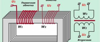
Therefore, some methods of adjustment, regulation, and adjustment of the mains voltage are needed. One of the best ways is to change the transformation ratio as needed by decreasing or increasing the number of turns in the primary or secondary winding of the transformer, in accordance with the well-known formula: U1/U2 = N1/N2.
To adjust the voltage on the secondary windings of transformers, in order to maintain the correct voltage value for consumers, some transformers have the ability to change the ratio of turns, that is, to adjust the transformation ratio in this way in one direction or another.
The vast majority of modern power transformers are equipped with special devices that allow you to adjust the transformation ratio, that is, add or subtract turns in the windings.
Design features, principle of operation
The on-load tap-changer, despite the nature of the action and the function performed, should not be classified as a relay. But this device has a simple operating principle.
Switching device system
Two moving contacts are installed on each phase of the transformer. One of them is pressed against the coil turn, which provides a given voltage value. During translation, the second contact is pressed against the coil, changing the specified value. Switching on can be done manually or using a drive.
The design of the device differs depending on its type. But the basic principle involves changing the number of working turns on the primary coil of the transformer.
How is the adjustment carried out?
Let's consider the process of voltage regulation on the reactor on-load tap-changer circuit.
The device works as follows:
- in the initial position, both selective contacts I1 and I2 are connected to one turn of the coil;
- if it is necessary to move to another stage, K2 opens (without turning off the voltage) with current passing through the reactor branch (I1 - K1);
- contact I2 is transferred to another turn, with contactor K2 closing;
- the operating current is divided between the reactor branches; the value of the equalizing current limits the reactor;
- then, after opening K1, I1 is transferred to another branch, followed by closing the contact.
Subsequent switches are made in a similar order.
The use of on-load tap-changers significantly expands the variable capabilities of transformers and ensures a change in the characteristics of the voltage supplied to consuming devices without turning off the current supply.
No-load voltage regulation: Switching without excitation - Off-circuit switching
A more detailed description of the on-load tap-changer can be found here: Read more
Source
Classification
There are several types of on-load tap-changers, differing in the following characteristics:
- a type of current-limiting element - with reactors or resistors;
- presence or absence of a contactor;
- number of phases – single-phase and three-phase;
- type of current switching.
Explanation of marking for on-load tap-changer type UBB...
Depending on the method of current switching, there are the following types of devices:
- the arc breaks in a volume filled with transformer oil - the device involves the use of arc extinguishing contacts that do not require the use of special elements to extinguish the arc;
- the arc breaks in a rarefied space - it is suggested to use vacuum arc extinguishing chambers produced industrially;
- shutdown is carried out using thyristors, in an arcless manner;
- combined methods - with a combination of different types of switching.
Also read: Calibration interval of current transformers
To ensure the safety and functionality of the on-load tap-changers, they are equipped with automatic monitoring elements and voltage regulators.
In addition to the above devices, special booster transformers can be used to change the voltage characteristics in powerful units. This equipment is connected in series and used together with the main unit as an auxiliary unit. But this method has not been widely used due to the high cost and high complexity of the circuit.
Methods for regulating transformer voltage under load
Voltage regulation of transformers using the on-load tap-changer method is carried out in principle in the same way as using the off-load tap-changer method, but the number of winding branches, i.e., the number of control stages, is usually greater, and the control range is wider. Thus, GOST 12022-76 for transformers with a power of 63-630 kVA established a voltage regulation range relative to the nominal ±10% in steps of 1.67% (±6X1.67%). GOST 11920-73 allowed transformers with a power of 1000-80000 kVA to have different control ranges: ±9, ±10, ±12%. There are series of transformers with an even larger range: ±16, ±22, ±36. Even more “deep” regulation is required for some special transformers, for example electric furnaces, where the ratio of the voltage regulation limits of the LV winding is often 1: 2, 1: 3 and even 1: 5.
Let's consider the most common operating diagram of a switching device with a current-limiting reactor (Figure 2). The switching device has the following main parts: tap selector, contactor, current-limiting reactor, device drive. The circuit has two outlet (current-collecting) contacts of the selector P1 and P2, two contactors K1 and K2, and a current-limiting reactor P (In is the rated current of the transformer).
Fig. 2. Schemes of operation of a switching device with a current-limiting reactor
- a — “two together” position;
- b - contact FK2 is open;
- c — “bridge” position;
- d — contact K1 is open
In Figure 2, a, both output contacts are installed on one branch of the winding. This position of the contacts is called “two together”. The rated load current is divided equally between the two halves of the switching device. If it is necessary to switch to another branch (stage) of the winding, the drive first opens the contacts of contactor K2 (Figure 2, b). These contacts break a current equal to half the rated current, and an electric arc occurs between them. After the arc is extinguished, all current passes only through the second (upper) half of the switching device. The tapping contact of the selector (P2), in the absence of current (the circuit is broken), moves to another branch of the winding, after which the contacts K2 close again (Figure 2, c).
This position of the switching device is usually called the “bridge” position. As in the two-together position, the load current rating is divided in half between each half of the switching device. However, in the “bridge” position, in addition to the load current, a circulating current appears, which closes inside the circuit formed by part of the transformer winding and the reactor (Figure 2, c). The amount of circulating current is limited by the resistance of the circuit - mainly the resistance of the reactor. Typically, the reactor resistance is selected so that the circulating current is equal to half the rated current. In this case, the current passing through the outlet contacts P1 and P2 will not be greater than the rated one and there is no danger of their excessive heating.
Next, contacts K1 open, breaking the rated current (Figure 2, d). After the arc is extinguished, all the current passes through the other half of the switching device. In the absence of current, the tapper output contact P1 of the selector goes to the branch where contact P2 is already located, contact K2 closes again and the switching ends.
From examining the operation of the on-load tap-changer, the following conclusions can be drawn:
- contactor contacts K1 and K2 close and open current, i.e. exposed to an electric arc;
- selector contacts P1 and P2 close and open without breaking the current, i.e. in the absence of an arc;
- the drive must provide the described sequence of contact operation;
- the reactor serves to limit the circulating current to the required value (for example, to half the rated load current);
- in the “two together” and “bridge” selector contact positions, the load current is distributed equally between the two reactor windings installed on the same core. These currents are directed towards each other and in the “two together” position do not create an exciting field in the core and a voltage drop.
The advantage of switching devices with a current-limiting reactor is the ability to operate for a long time in the intermediate “bridge” position, therefore, to drive these devices no special high-speed mechanisms are required, which means they can be relatively simple and cheap.
In recent years, other switching devices with active current-limiting resistances have become widespread. Without considering these devices in detail, we note that their design is more complex and expensive than that of switching devices with reactors. However, they have a number of very significant advantages: the bulky and heavy reactor is replaced by relatively light active resistances; These devices are structurally more compact; arc extinction conditions are more favorable.
There are many schemes for adjustable transformer windings. Figure 3 shows, as an example, a circuit of a high-voltage winding of a single-phase transformer, regulated by a switching device with a reactor.
Figure 3 — Diagram of the HV winding of a single-phase transformer, regulated by a switching device with a reactor
On-load tap-changer protection
To ensure normal operation of the device, gas protection is used. An additional container (expander) is made, connected to the main oil medium of the transformer by a special channel in which a relay and a signal element are installed.
If gas formation is slight, the signal element indicates a decrease in the oil level. In the event of a blowout, the expanded oil is forced into the conservator. If the surge intensity reaches the set value, the relay is activated, turning off the transformer. In this way, the on-load tap-changer contactors are protected from destruction.
Anzapf device
A transformer trunnion is a simple device in the form of a turn connection, which is associated with a switch and a winding on the high side. The adjustment is made in two directions: upward (decreasing) and downward (adding). All this is characterized by the physical law of Ohm, which assumes a proportional ratio of resistance to voltage level.
To understand the position of the transformer trunnion, you need to look at the nameplate symbols. Each step involves a 2.5% change either down or up. To maintain the stability of the contact resistance, a spring device is used.
Note that over time, the insulation resistance may decrease, so the device must be transferred at least 2 times a year. Once a year, physical measurements of the windings should be carried out using a megger or other insulation service equipment.
Advantages and disadvantages of regulation using on-load tap-changers
The advantages of regulation without disconnecting the load are the ability to maintain network parameters at the output of the transformer at a given level when the characteristics of the supplied voltage change. This device also allows you to adjust the parameters, taking into account the required value. The specified functions are achieved without shutting down the unit.
The disadvantages are associated with the need to complicate the design of the transformer due to the use of additional elements. At the same time, the reliability of the unit’s operation decreases, its weight and overall dimensions increase.
Similar
| Russian Federation Guiding normative document standard technological... The instructions are intended for personnel of power plants, electrical network enterprises, repair enterprises and organizations of the Ministry of Energy... | Russian Federation Guiding normative document standard technological... The instructions are intended for personnel of power plants, electrical network enterprises, repair enterprises and organizations of the Ministry of Energy... |
| Monitoring the condition of transformersDifferent purposes, often associated with differences in design, various operating conditions and other features require different... | Standard operating instructions for generators at power plants rd 34. 45. 501-88 Developed by the All-Union Scientific Research Institute of Electric Power Industry (VNIE) |
| Standard operating instructions for automatic water treatment plants...Developed by the joint-stock company Company for adjustment and improvement of technology | S. D. Lizunov drying and degassing of high voltage transformersThe proposed review of foreign literature in recent years examines the issues of drying and vacuum treatment of transformer insulation... |
| Training course, lecture contentChecking power transformers before putting them into operation Methods for drying transformer insulation | Instructions for testing voltage transformersThe instructions provide a program and methods for testing voltage transformers (TV) and their secondary circuits. Basic information about... |
| Recessed LED luminaires al 501 Operating instructions The luminaire is designed for general lighting of offices, trade and exhibition halls, catering premises, shops… | The book is intended for a trained reader familiar with the theory... The book is intended for undergraduate and graduate students of energy universities and engineering and technical personnel of transformer plants,... |
| Operating manual for hand 442273. 501 ReThis operating manual, combined with a passport, certifies the main technical characteristics of the device for determining... | Terms of reference for the implementation of work on technical re-equipment...Ascue, current transformers and voltage transformers of turbogenerators TG-1, TG-2 and TSN 21T, 22t of the Simferopol thermal power plant to modern... |
| Instructions for commissioning and loading and unloading...Every employee who has anything to do with the transportation, installation, maintenance and use of current transformers (abbreviated... | Operating manual for hot wedge welding machine TN-501Pvc), eva, hdpe (HDPE), pp (polypropylene) and other materials subject to thermofusion |
| Guidelines for the operation of fuel oil heating facilities...Approved by the chief engineer of the Branch of OJSC "Engineering V. A. Kupchenko 04.04.2005 | Technical description and operating instructions -1The installation type im-65 (hereinafter referred to as the installation) is intended for testing the insulation of power cables with rectified voltage... |
ROSPRIRODNADZOR
It greatly simplifies the process: preparing a document in the required format for each type of pollution, checking it and sending it directly to the website of the executive body in Kontur occurs automatically. Afterwards the declarant receives a letter about the status of delivery of the document. If for some reason it was not possible to upload it to the Rosprirodnadzor portal, it is saved in the archive and, as soon as the load on the site becomes less, it is loaded from the “queue”.
The main advantages of the Kontur.Extern system are:
- Legislative relevance: the service is updated in accordance with each new law or amendments.
- Easy and quick calculation: when you first download “Contour”, it is enough to indicate complete information about the enterprise, its activities, sources of pollution; the data will be downloaded automatically during subsequent shipments.
- The filling is always 100% correct; after an automatic check by the system, the user receives an offer to correct any errors found.
- The reporting document is sent in one click.
Important to know: The cost of the “Reporting to RPN” tariff is 4,300 rubles per year. For Kontur.Extern subscribers, an additional certificate is not required. If the connection is primary and you need to submit reports only to the RPN, then the issuance of a certificate is included in the cost of the “Reporting to the RPN” tariff. To issue a certificate you need: a passport, SNILS and an application for the issuance of a certificate.