Seal
Power supply repair
Photo of TV power supply
Among all faults, repair of power supplies ranks first. In the article “TV power supply malfunctions” I described typical malfunctions of power supplies. In this article I want to describe the operation and repair of power supplies in more detail.
You probably need to start with how to check the power supply after repair, so as not to cause it to break again. Although this method is considered controversial, I find it very effective.
So, after repairing the power supply, you need to solder a light bulb with a power of 150 watts into the fuse gap (100 watts is possible, but there may be a false glow), and solder a light bulb into the B+ circuit gap (line scan power 95-145 volts, the track can simply be cut) 40-60 watts. Please note that some power supplies do not start with a small load.
This is how this system works. When plugged into the network after repairing the power supply, if it is in good working order, the first light bulb lights up at the moment of charging the mains capacitor (100-220 µF 450V) and goes out as it charges. A weak glow remains. A 60 W light bulb glows according to the voltage at half incandescent.
If the power supply is faulty, a 150 W light bulb glows at full intensity. In some cases, this saves a transistor or a microcircuit from repeated failure of key elements.
In the second method, the power transistor of the power supply is not soldered in and the level and shape of the signal arriving at it are analyzed using instruments (oscilloscope, multimeter).
Power supply repair.
In the description I will rely on the diagram below.
Content:
- 1 Reasons for power supply failure
- 2 Diagnosing a TV malfunction
- 3 How to get to the board
- 4 Board diagnostics 4.1 Detailed fault diagnosis
A faulty power supply is the most common reason for a TV or monitor not turning on. Temporary factors, voltage drops in the network, interference with the operation of the device, temperature changes - all this can lead to damage to the power supply. The power supply itself is a rather complex element of the circuit, and often diagnosing a fault takes much more effort and time than repair work. Whether to repair the switching power supply yourself or entrust it to specialists from the service center - everyone decides for themselves. It should be borne in mind that repairing such a complex element will require the necessary tools and basic technical knowledge.
Troubleshooting
First of all, it is necessary to discharge the input capacitors. If this is not done, then during the repair process there may be a short circuit or other problems that will lead to more serious damage. To discharge, you can use a low-resistance resistor, a tester or a regular light bulb, brought to the contacts for a few seconds. After this, you can unsolder the damaged capacitors and replace them with working ones with the same power.
Important! Any repair of a power supply is associated with a number of risks. If you act carelessly, you can cause even greater harm to the TV or even your own health. If you have any doubts about your own abilities, you should trust the repair procedure to an experienced technician.
A video lesson from a master will tell you in detail about the entire process of repairing a power supply:
Reasons for power supply failure
The power supply for a TV is a board on which there are transformers, a fuse, capacitors, a PFC unit, an inverter and a standby power supply; some models are also equipped with a diode bridge. Failure of each of the board elements can lead to complete failure of the TV. Faulty equipment can behave in different ways:
- The TV simply does not turn on and does not show any “signs of life”.
- There are several attempts to turn on, after which the TV turns off completely.
- Noise appears from the back wall of the TV: crackling, knocking or whistling.
- The indicator light does not light up.
- The TV randomly turns off.
- To achieve a normal signal, you can only turn the device off/on repeatedly.
- There is a delay in the image after turning on.
Problems with picture or sound quality are often not related to the power supply. The main symptom of a faulty power supply is the inability to turn on the TV.
There are actually many reasons for the failure of the power supply for a TV, and the breakdown is not always the fault of the user or improper operation of the device. The most common causes of malfunction are:
- Voltage fluctuations in the network. A sharp drop has a much more detrimental effect on the radio elements of the board than just increased or decreased voltage.
- Current surge. As a rule, modern apartments and houses are protected by automatic circuit breakers that turn off the power to electrical appliances when the current reaches a critical level. But a lightning strike during a thunderstorm can provoke a sharp and uncontrollable jump in current readings. Old LCD TVs are especially sensitive to this.
- Incorrect operating conditions. When working in humid conditions, moisture gets onto the TV board, and with sudden temperature changes, condensation forms on it. Moisture can cause failure of individual board elements.
- Short circuit. By analogy with a lightning strike, a short circuit provokes a sharp jump in critical current indicators. Unfortunately, machine guns do not always have time to protect equipment.
- Time factor. All BC boards have storage elements - capacitors. Over time, capacitors fail, swell, and this leads to malfunctions of the TV's power supply. It is impossible to influence this factor.
- Handicraft renovation. If the owner of the equipment has recently turned to uncertified technicians for help, there is a high probability that the breakdown was caused by their “repair”. After the work of unqualified specialists, “extra parts” may remain; they may make assembly errors and make incorrect connections.
Knowing the cause of the breakdown, it will be much easier to find the fault, since it will be clear where to look for the problem. But, before you start repairing the TV power supply, it is worth carrying out a full diagnosis and making sure that the fault is in the BC.
Manifestation of a malfunction - how to identify a broken TV unit
Whatever the breakdown of the power supply, it will certainly affect the operation of the TV. Damage to this element is primarily indicated by the following signs:
- The TV does not turn on;
- the indicator light does not light;
- You can hear the whistling of the pulse transformer, while the TV does not work because the power supply protection device is activated (this may also be a sign of failure of the LED backlight).
When the TV is turned on normally and various abnormalities in sound or image appear, these disturbances are most likely caused by some other reason, and not by a breakdown of the power supply. At the same time, there are some exceptions to this rule when the problem that arises is in one way or another connected specifically with the power supply:
- the indicator lights up, but the TV does not start in operating mode;
- when you press the power button on the device itself, the TV does not start;
- At first only sound appears and only after some time does the image appear;
- normal picture display and sound playback appear only after the TV is turned on and off repeatedly;
- the appearance of stripes, background sound, and a broken image are observed.
Diagnosing a TV malfunction
At the first symptoms of a breakdown, do not immediately disassemble the TV and remove the power supply. The fact is that the cause of the problem often lies in the outlet. First of all, you should check the presence of voltage in the network; there may be a fault in the wiring. Moreover, the presence of light or working sockets in other rooms does not mean anything, since the wiring can only be routed to one socket and pass through a separate circuit breaker. You can check the presence of voltage in the network using a conventional indicator.
If there is voltage, you should check its numerical value. This can be done using a regular multimeter. Almost all modern TVs are designed for an operating voltage range of 210-250 V. But in some cases, the voltage can drop to 190 or even 170 V. The TV won't turn on just because it doesn't have enough power. In this situation, you will either have to resolve the issue with the energy supply company or resort to purchasing a stabilizer.
The stabilizer will also help protect the TV from harmful power surges in the network.
If everything is fine with the power supply and voltage, the problem is really in the TV itself. And if it does not turn on, then everything lies in the malfunction of the power supply itself. What else you should pay attention to:
- Does the TV make any strange sounds - crackling, knocking, whistling or beeping?
- Is the indicator light on?
- Is the back of the TV getting hot?
- Does anything happen when the TV is connected to the network?
Next, you can begin to disassemble the TV and remove the power supply board from it to search for local faults.
How the power supply works and looks like, its components
Before the 1970s, most consumer electronics used a power supply such as a power transformer, or rectifier, or filter capacitor to convert the AC line to the various voltage levels needed for internal circuits. Many of them were not even regulated.
Nowadays, all televisions, monitors, PCs, laptops, video cameras, printers, faxes and even certain audio equipment use switching power supplies.
Switching power supplies or switching power supplies (SMPS) are an electronic circuit that converts energy using:
- Switching devices that turn on and off at high frequencies;
- Storage components, such as inductors or capacitors, to supply power when the switching device is in a non-conducting state.
Switching power supplies have high efficiency and are widely used in various electronic sensitive equipment that require stable and efficient power supply.
Switching power supplies are classified according to the type of input and output voltages. Here are the four main categories:
- AC to DC;
- DC to DC;
- DC to AC;
- AC to AC,
where AC is alternating current and DC is direct current.
In direct current, electric charge flows in only one direction. The electric charge of alternating current periodically changes direction. The voltage in AC circuits also periodically reverses as the current changes direction.
Most modern digital electronics use direct current. However, it is important to understand some AC concepts. Most of our homes are connected to AC power, so if you plan to plug an electronic device into an outlet, you will need to convert the AC to DC.
Alternating current has its undeniably useful properties, such as the ability to convert voltage levels using a single component (transformer), which is why alternating current has been chosen as the primary means of transmitting electricity over long distances.
Now let's understand the working principle of different power supplies. A conventional (linear) power supply uses a transformer to change the voltage to the required level. The circuit then changes this to constant current, ensuring it is clean and remains at the proper level (rectification, filtering and regulation). The problem with this design is that the line frequency transformer devices are large, heavy and expensive.
The key to the operation of a switching power supply is to operate the transformer at a much higher frequency, most often beyond audible frequencies. At higher frequencies the iron core of the transformer is no longer needed, so the design is more compact, lighter and potentially more stable than the old linear design.
But in order not to go too deep into the technical jungle, let’s move on to more tangible parameters. What does a switching power supply for a TV look like and what components does its design consist of?
In modern TV models, power supplies are located on the system boards, and there are several of them, or rather, most often three:
- Power supply unit on duty;
- Inverter block;
- PFC block.
All these components are yellow-black in color.
The duty power supply is the device that is responsible for lighting the indicator on the front panel of the television receiver. It always maintains a minimum voltage of 5 volts so that the user can turn on the equipment from the remote control.
Inverter Unit – This system component is responsible for supplying voltage to the inverter converter. Inverters produce a fairly high voltage level for power (500 to 700 volts) and light up your LCD screen. A faulty or damaged inverter board may cause picture distortion, darken the screen, or prevent it from turning on. If a breakdown occurs in the inverter power supply, then your TV will go into standby mode immediately after turning on.
The PFC unit is the component responsible for correcting the power factor - the relationship between kW and kVA consumed by an electrical load, where kW is the actual (real) power of the load, and kVA is the total (nominal) power consumed by the load, which is not all used as effective energy. Simply put, it is a measure of how efficiently load current is converted into useful operating power.
When designing an AC-powered electronic power supply, strict adherence to PF limits and performance standards is required. This is typically achieved by introducing an active or passive power factor correction (PFC) circuit within the power supply.
As can be seen from the description, the TV power supply is not just a separate device that can be easily replaced (although there are such TV models). This is a whole unit that consists of several components, each of which is responsible for its own direction in providing the receiver with a voltage of a certain power.
How to get to the board
Depending on the model and generation of the TV, the power supply may be located differently. In any case, you will need to remove the back cover from the TV, which is secured around the perimeter with small bolts. After removing the cover, the BC board will be visible - it can either be exposed or hidden behind an additional protective cover. The easiest way to determine the location of the power supply is by the incoming power connector, where the cable comes from the network - that’s where the board is located. If the BC is covered with protection, it will also have to be removed by unscrewing the bolt around the perimeter of the casing. Once the board is exposed, it can be removed. You can do this as follows:
- Unscrew the bolts used to secure the board.
- Disconnect the cable that can connect the power supply board to the secondary board.
- Disconnect all wires leading to the secondary board.
As a rule, one cable and one or two wires with special connectors are used to connect the BC and the secondary board.
Important!!! All manipulations should be performed after disconnecting the TV from the network. Working with a board that is live can be life-threatening!
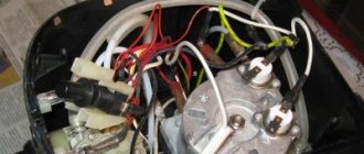
How to connect?
Let's take a closer look at how to connect the power supply. In most cases, the amplifier is already built into the active antenna. But in passive it is not there. To connect it, you first need to assemble an antenna cable with a plug that will be intended for these purposes. Let's look at how to do this.
First you should prepare the cable itself, that is, strip it. To do this, use a sharp utility knife or scalpel to make a thin incision around the circumference at a distance of 1.5 cm from the edge of the cable. When performing this work, it is very important to be careful and try not to damage the hairs of the shielded braid located immediately under the insulating layer.
After these steps are completed, the mentioned hairs must be carefully bent back and the piece of foil located near them must be removed.
Stepping back approximately 5 mm from the folded edge of the braid, you need to make another cut around the circumference. It is necessary to remove the inner insulating layer. After this, the cable, prepared for installation, should be inserted under the appropriate fasteners in the power supply box and tightened with screws.
We pay special attention to the fact that when a wire is connected, its metallized braid must have contact with a tinned pad, which is a mandatory design element of any power supply housing. If this is not done, then the antenna simply will not receive power. It is also necessary to take into account the fact that the cable braid should under no circumstances come into contact with the central core of the wire itself. If this happens, a short circuit will occur and the module operation indicator will not function.
For information: if the power supply is correctly connected to the antenna cable itself, after making all the necessary settings, the TV usually shows many more channels than before.
Board diagnostics
As soon as the board has been removed, it is necessary to conduct an initial inspection for obvious damage. What to pay attention to:
- Are there any traces of burning? In some cases, certain elements may burn out, leaving behind soot.
- Solder debonding. Over time, poor-quality soldering can lead to one of the elements simply falling off.
- What do capacitors look like? Swollen capacitors are not always visible to the naked eye without using a multimeter, but if you manage to notice an objectively “inflated” capacitor, then it is obvious that it has failed.
- Integrity of connectors. Make sure that all connectors are not damaged. This applies to both the power input connector and the output connections to the secondary board. It is important that there are no traces of melting on the plastic input connector.
If there is nothing like this on the board, further search for the problem is carried out using a multimeter. First of all, you need to ring the fuse for integrity; if it does not ring, the cause of the malfunction is obvious. Replacing the fuse is the least of the problems that may arise when repairing a switching power supply with your own hands.
Under no circumstances should you install a replacement fuse with a higher rating, as this can lead to failure of more expensive elements. Also, you should not completely throw away the fuse, replacing it with a “twisted” one!
If the fuse is intact, you should check the capacitors, namely, measure the capacitance of each of them. You can also simply test them for integrity, since often the cause of capacitor failure is a break and breakdown. The capacitor rating can be found on the element itself. Even a 10% deviation from the nominal value requires a complete replacement of the elements.
Another way to test capacitors is to power the board from the mains and measure the board's output voltage. If it is below 5V, then the problem is in the capacitors.
If non-working, swollen or broken capacitors are detected, they must be replaced. Moreover, it is recommended to change all capacitors at once, since they usually fail one after another, and if one element is swollen, others will soon swell. You should also pay attention to the TV's power cable. It is enough to ring it for integrity. It happens that the problem lies in the connection of the cord and plug, as well as in the violation of the integrity of the wires.
Before diagnosing capacitors, they must first be discharged. This can be done using a regular light bulb, bringing it to the contacts of the capacitor. Otherwise, a short circuit may occur, which will lead to even greater damage, and there is also a risk of electric shock.
Detailed fault diagnosis
If the initial inspection of the board and checking for the most common breakdowns do not produce any results, you will have to resort to detailed diagnostics. To do this, you will need a circuit diagram for the TV's power supply, which can be downloaded from the manufacturer's official website. Next, using a tester (multimeter), the following checks are carried out:
- It is necessary to ring each element of the network (diodes, transistors, capacitors).
- We check the ballast resistance - the resistor for a break.
- You should also check the rectifier diodes, which often fail after a short circuit in the network.
Having identified a damaged board element, it will need to be replaced and a repair check performed.
Diagnosis of the TV power supply before repair
To perform a competent diagnosis of a power supply failure, you need to carry out several step-by-step actions.
Disassembling the TV
Determining the cause of the problem begins with disassembling the device. To do this, unscrew the screws from the back cover of the TV to open access to the power side.
In different TV models, power supplies are located differently, so it is not always possible to immediately see this element after removing the cover. If this is your case, then access to the power supply is most likely blocked by a protective metal casing.
In some TV models, additional protection may be installed specifically for the power supply. In this regard, you will have to go through several stages of unscrewing the screws that secure the desired part.
Familiarization with the power supply device
To take further actions, you need to clearly understand what the components of the TV power supply look like. All modern models have not one power supply, but several. They are usually located in one place - the board. This board is easy to distinguish from others: in addition to capacitors and other components, it contains 3 black and yellow transformers.
The TV power supply consists of the following components:
- Standby power supply . Its main function is to keep the TV in standby mode and await subsequent commands. A glowing LED indicator indicates that you are in this mode. For normal operation there must be a voltage of 5V, the supply of which to the TV is provided by the duty element.
- Inverter block . The main function is to provide power to the processor. If this function is violated, when you try to turn on the TV, an instant transition to sleep mode is observed. This occurs as a result of the fact that the processor, without receiving confirmation of functionality from the inverter, stops activating further actions and returns to standby mode.
- PFC block . The main task of this component is to correct the power factor, which can be reactive or active. The first is necessary for the operation of the TV, at the same time it can significantly increase electricity consumption and affects the rapid wear of capacitors, which negatively affects the service life of the power supply as a whole. Active power carries out a useful action, and reactive power only transfers to the load from the generator and again to the generator.
Important information about power supplies:
The structure of the TV power supply and its main components is described in this video:
Troubleshooting
After familiarizing yourself with the components of the device, proceed to diagnose it. Using a tester, ring the output of the standby power supply - the result should be 5V. If the voltage is less than this indicator or is completely absent, the problem is most likely failed capacitors. To determine this, a simple inspection of these parts is enough - they will be convex.
The most vulnerable components of TV power supplies include filter capacitors, which lose their nominal properties faster than others. However, the damaged element does not always have visible damage. Poor-quality filtering leads to inoperability of the power supply, failure of the inverter, and software failures of the microcircuits on the board.
If the capacitors are OK, check the fuse. For this purpose, a ring is used, which will reveal the presence or absence of a short circuit.
You should also test the board from the back side, for which you must first remove the element from the frame. Check the resistors for the following deviations:
- darkening;
- cracks;
- poor soldering of leads;
- gaps between tracks.
All this can be tested visually, and then a decision can be made on how to solve the problem. If the inspection shows nothing, check the resistors with a multimeter. A fault will be indicated by zero resistance.
Replacement of damaged elements
To repair the power supply board, you need to find replacements for all failed elements. You can buy diodes, capacitors and transistors at any radio electronics store or in specialized online stores. As soon as all the necessary elements are available, you should prepare for the work. For repairs you will need:
- Soldering iron with the ability to regulate the heating level.
- Screwdrivers.
- Wire cutters.
- Tweezers.
- Multimeter.
- Solder.
To remove a faulty element, you need to turn the board over and heat the solder, which fixes the “legs” of the element with the common track of the board. Once the tin is melted, the legs can be removed by pulling on the base of the element. Next, it is recommended to remove the remnants of old solder from the place of work and directly in the holes of the board under the legs. This will allow you to solder new elements more reliably. After inserting the legs of the new element into the holes, secure them with tin. This must be done extremely carefully, using a small amount of solder. Otherwise, the connection of adjacent elements may be affected.
When all repair work is completed, you can check the performance of the power supply. But before you check the TV's power supply for proper operation, you should carry out an additional check. To do this, simply remove the fuse and replace it with a regular incandescent light bulb. If, when power is applied to the board, the lamp filament becomes hot, then you can try connecting the board.
Step-by-step instructions for repairing a TV power supply
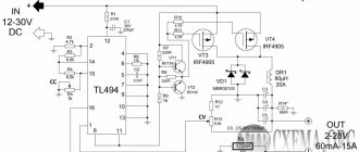
Power supplies for modern TVs usually have a standard circuit. The existing differences boil down only to the size of the electronic elements and output power. In this regard, diagnostics and repairs occur using the same method.
Typical power supply circuit for a foreign TV:
Required tools and materials
For repairs, you should stock up on tools and materials, without which it will not be possible to properly fix the problem:
- soldering iron with adjustable power;
- solder, alcohol (refined gasoline), flux;
- melted solder remover;
- screwdrivers included;
- nippers (side cutters);
- tweezers;
- tester (multimeter);
- lamp 100 watt.
When starting to repair a TV power supply, you need to have a schematic diagram of the model on hand (if you don’t have one, you can download it online from the manufacturer’s official website).
Checking the results of repair work
Upon completion of the repair, you need to mount the board back into the TV. To do this, all cables and connections are connected to the secondary board, and the power supply board itself is attached using one or two bolts. The first test should also be performed without the fuse, replacing it with an incandescent light bulb. If, when you connect the TV to the network, the lamp lights up and the TV itself operates normally, it means that the repair was performed correctly. All that remains is to replace the fuse, fix the board, cover it with a protective casing (if there was one) and secure the back cover of the TV.
But even after replacing the burnt-out board elements, the TV may not turn on. Failed elements during operation could lead to more serious damage. An experiment with a light bulb will reveal other faults:
- If the light comes on, but immediately goes out, and a characteristic raster appears on the screen, it is necessary to replace the optocoupler pairs.
- If the lamp lights up and goes out, but the TV indicator never lights up and nothing appears on the screen, you should look for the problem in the pulse generator area. It is recommended to check the voltage on the high voltage capacitors and recheck the integrity of the rectifier diodes.
- If the lamp burns brightly, there is a breakdown in the circuit, and high voltage is supplied to the area where there should be 5V. We check the output voltage of the transformer, and if it is damaged, the entire power supply must be replaced. If the transformers are intact, it is necessary to re-check and identify the “broken” element.
- If the lamp does not light, there is an open circuit. In this case, the integrity of each element is also re-checked by ringing with a multimeter.
The most unfavorable outcome is a break in the transformer winding. It will be extremely difficult to carry out such repairs, and most likely, the power supply itself will be replaced, which will cost several thousand rubles.
Algorithm for finding a breakdown and repairing it
Repairing televisions and other household and industrial equipment can be profitable and cost-effective, but only if you have a minimum of technical literacy and are familiar with all relevant safety precautions. Not every amateur can repair a power supply. This is a very difficult and unsafe activity.
But if you still feel confident and want to understand the reasons why your TV is not working, in particular, check its power supply, we will suggest you perform the following sequence of actions:
- Unplug the TV and check the socket itself: the problem may be an unstable network voltage or a malfunction of the socket itself (or extension cord).
- Discharge the high-voltage capacitor on the board so that there is no short circuit in the future (you can simply short-circuit it with an insulating screwdriver, a tester, or hold a light bulb to it for a couple of seconds).
- If everything is fine with the power supply in the system, then the next step is to dial the standby power supply, in which, as was written earlier, the voltage should be maintained at 5 volts. If less, you will need to check the capacitors.
- Now check the fuse - often due to a temporary overload or due to a short circuit in the mains voltage circuits, this part may simply burn out.
- Now remove the TV case and remove the motherboard.
The actual cause of fuse failure can be power surges, sudden shutdowns, lightning strikes or random power failure. Important! You can only replace a blown fuse with a part of the same rating recommended by the manufacturer of the electronic device!
After this, place the board on a flat surface and conduct a visual inspection:
- Check the board itself for ring cracks;
- Using a special voltage measuring device (tester), check each resistor, transistor, electrolytic capacitor, diode;
- Carefully inspect all soldering areas, the continuity of etched tracks, whether there are breakdowns, breaks, etc.
If you notice a darkened or cracked resistor, it will need to be replaced. The resistance of these elements with values in the range from 0 to ∞ is also a sign of their inoperability. If there are capacitors on the board with a swollen top cover, they will also have to be replaced.
The operation of silicon diodes can be checked in two ways:
- Unsolder the board and check the voltage with a tester (in mode with a limit of 20 kOhm): in the forward direction the value should be 3-6 kOhm, in the reverse direction – ∞;
- The soldered diodes are checked with a multimeter in the voltage drop measurement mode - the value should be up to 0.7 V (if the voltage is 0 or close to that, then the element will still have to be unsoldered and checked using the first method).
Bipolar transistors need to be checked twice: both in the forward and reverse directions.
To check the supply voltage of a switching power supply, do the following:
- Take a circuit and 2 100-watt light bulbs.
- Determine where the horizontal scan output stage is located.
- Unplug it and plug in a light bulb instead.
- Find the power filter capacitor in the secondary circuits and connect a second light bulb to it, which will create a load simulation.
If the light comes on, this indicates that there are problems in the power supply: in the input circuits, rectifier, network, power capacitor, etc. But if the light comes on, goes out, and then lights up very poorly, then the power supply is normal. And the diagram will be needed in order to determine exactly where the gap formed.
If the power is turned off and the fuse has not blown, then most likely there is a faulty starting circuit (open starting resistors), open fusible resistors (due to short semiconductors), faulty controller components.
Diagnosing problems in switching power supplies is sometimes complicated by the interdependence of components that must function properly in order for any part of the power supply to perform its part of the operating process.
Depending on the design, an SMPS may or may not be overload protected: one model may fail catastrophically under heavy load, even if there is a short circuit protection fuse. In another power supply, communication devices (often 800 V transistors) may fail.
In addition, such equipment may malfunction when power is restored after a power outage. This moment is very tense: any power surge is undesirable. (Some designs take this into account and limit the turn-on jump).
However, the cause of many problems is immediately obvious and has simple fixes - the weakest link in their composition is a blown transistor chopper or a dry main filter capacitor. Don't assume that all power supply issues will always be complicated and confusing. In most cases no.
Do it yourself or contact a service?
Repairing a television power supply board is a rather labor-intensive process that is associated with high risks. Lack of sufficient knowledge and practical skills can lead to the fact that a small malfunction due to improper repair will turn into big problems. Also, without the proper knowledge and safety measures, an amateur repairman runs the risk of receiving an electric shock up to 220V, which can result in a critical threat to life and health. Therefore, if you have the slightest doubt about your own abilities and qualifications, you should contact the service center.
PSU repair is the most common type of repair performed by TV repair technicians. Therefore, they already know how to restore power supplies quickly and efficiently. The cost of repairs usually does not exceed 2,000 rubles, excluding the price of elements to be replaced. Moreover, in large service centers there will always be extra capacitors, transistors and diodes, so you don’t have to find out where to buy them, search all over the city or wait for an order from an online store.
What it is?
In the most general sense, the power supply is a source of electricity that supplies the TV with the necessary current . This module allows you to convert the mains voltage to the values necessary for the full functioning of the equipment. As a rule, a power supply is included in antennas with an amplifier in order to improve signal reception.
Article on the topic: How to replace a TV on a VAZ 2110
Power supplies are universal devices; they can be installed in other devices: to improve the signal quality of cellular, satellite communications and even the Internet . The power supply is indispensable in a situation where a Wi-Fi adapter is used; by the way, it is also one of the types of antennas. Simply put, wherever radio waves are used and there is a receiving antenna, a power supply is needed.
But we will consider only those varieties that are required for the smooth operation of television equipment.
Please note: the relevance of installing and maintaining the power supply is directly related to the fact that in its absence, repairing it can be very costly or even impossible.
The television power supply performs three main functions:
- converting the energy of current supply into equipment;
- protection against supply voltage interference;
- maintaining the required voltage level inside the TV itself.
The most widespread are modern systems operating from standard 220 W networks. Such elements can be built into a single antenna structure or located separately when the connection is made through a port.
When it comes to built-in models, a transformerless circuit is usually used. In this case, energy conversion is carried out due to pulse width modulation. Such power supplies are plugged into the most ordinary outlet, their calculated power is 10 W. This parameter is quite sufficient to provide power to the antenna. Such elements are quite compact and do not take up much space, but in the event of a malfunction they immediately lead to the failure of the entire signal reception system.
Article on the topic: 15 inch TV how many centimeters
Therefore, it may be more practical to purchase external devices . They are focused on the fact that in the event of a power supply failure, some signal will still be preserved, although, of course, it will not be good. In any case, another advantage of external power supplies is that they can be quickly and easily replaced if necessary.
The operating scheme is based on a transformer . In this case, the output voltage of the power supply is stabilized in a parabolic manner; the typical parameters for the output voltage are 24, as well as 18, 12 and 5 W. More precise figures are determined depending on the technical and operational parameters of the antenna.
How to prevent further damage
After successful repair, installation of the board in place and completed checks, care should be taken to ensure that the TV does not break down again. It is impossible to completely insure against breakdowns of complex equipment, but it is possible to eliminate the factors that disable the power supply:
- Solve the problem with voltage drops by installing a stabilizer.
- Install additional automatic protection against network overload and short circuits.
- Eliminate excessive humidity in the room where the TV is used.
- Make sure that you are using a working outlet and a quality extension cord, and that the TV's power cable and plug are not damaged.
- If any symptoms of a malfunction occur (noise, long startup time of the TV), do not start the problem and carry out repairs in a timely manner.
The only elements subject to the time factor are capacitors. Otherwise, it is much easier to prevent a malfunction than to repair it later.
Found a mistake? Select it and press ctrl+enter
- 100
Causes of the malfunction and ways to eliminate it
The prerequisites for a situation in which the TV does not turn on vary. Cases when the indicator works in normal mode, but the TV refuses to work, are quite frequent. The sensor may light up red, but the TV does not start using the button or remote control. There are also frequent situations in which the LED sensor does not light up and the device itself does not work, or a clicking or hum is heard from its body. The cause of the breakdown may lie in the failure of the electronic “stuffing”. The TV device may not start due to power failures.
Protection triggered
This is one of the likely reasons why the TV does not turn on. It may try to start, but the screen immediately goes blank or the device does not perceive the start at all. The prerequisite for this is voltage drops in the electrical network. This way the TV's electrical system protects itself. To resolve the issue, you should briefly deprive it of power by unplugging the power plug from the outlet. After restoration, the device will begin to function again. If there are constant fluctuations in the network, it is recommended to run the TV through a stabilizer.
Article on the topic: How to make a toy TV out of a box
Electronics faulty
If the TV does not turn on, this may be caused by failure of electronic components: capacitors, fuses or resistors. In this case, it is better to entrust diagnostics and repair work to specialists from a service workshop. Do-it-yourself repairs can be expensive, including purchasing a new TV. This task can only be done by service engineers with the appropriate skills.
Processor faulty
Modern television panels contain a large number of control electronic systems, which are mini PCs equipped with an autonomous central processor. If the TV does not turn on and this is caused by a CPU failure, the most advisable solution would be to contact a professional. Fixing this problem yourself will be very difficult and risky.
There is no voltage at the socket
There are situations in which circuit breakers in switchboards spontaneously trip, resulting in the outlet being de-energized. Its diagnosis can be carried out using a multimeter. The problem can be resolved by turning on the machine or replacing the electrical outlet.
Extension cord malfunction
The reason is quite common in cases where the TV does not turn on. This is easy to check - the TV device is connected directly to the outlet and, if it works, then the cause is indeed a faulty extension cord.
Wrong mode selected
Out of ignorance or mistake, the user may incorrectly select the operating mode, and then the TV may turn off or go into sleep mode. Resetting the settings will help eliminate this issue.
The TV does not turn on, the indicator is on
A burning sensor indicates full power supply. If the TV broadcasting device refuses to be started by the remote control when the indicator is on, you need to try to do this using the button on the TV (perhaps the reason is due to problems with control via the remote control). The problem can also be caused by a violation of the ceramic resistance (it is likely to break). Operation will be restored after replacing the resistor.
Article on the topic: How to connect a dish to an LG TV
In addition, if the TV does not turn on, but the indicator is on, you need to check the condition of the contacts (for the presence of oxide), the serviceability and charge of the battery in the remote control. Next, the buttons are diagnosed and the infrared emitter is checked, which are characterized by sticking and failure to respond to commands.
The cause of the problem may also lie in the electronics - something could have caused the capacitors to fail, so the power supply is not able to start the TV. Fixing this problem will require knowledge and time.
Professionals recommend disassembling the remote control from time to time and cleaning it from dust, which adversely affects the performance of its functions. It often happens that the remote control is filled with some kind of liquid and is no longer able to function. In most cases it will need to be replaced.
The TV does not turn on, the indicator light is blinking
If the TV does not turn on and the indicator light is red or the red light is flashing, this means that it is performing a self-diagnosis to identify the problem as well as its cause. On most modern models, repeated blinking (with a different number of times) indicates a corresponding error. The decoding of the light codes can be found in the attached instructions. Many TV brands have the self-diagnosis function: Panasonic, Philips, Sony, etc.
Via standard buses, the CPU receives information from all TV receiver systems. Having detected a faulty node, the central processor will block the start command. If you find that the TV does not turn on, but the indicator is on, you will need to decipher the indicated error, which will allow you to eliminate it.
Article on the topic: How to connect two TVs together
A similar phenomenon can also be observed when the television panel serves as a monitor for a PC. When it goes into sleep mode (or turns off) and then presses the start key via the remote control, the panel will signal by flashing the LED.
The TV does not turn on, the indicator does not light up
A direct or indirect reason for this manifestation may be a lack of power supply. When the LED burns out, the TV continues to function in its normal mode, but with no indication.
A malfunction may occur as a result of a malfunction of the fuse-resistor or a malfunction of other electronic parts. After replacing the failed component, the TV broadcaster will resume its operation.
Having ruled out all possible violations that can be corrected on your own, you should then move on to more complex ones. But in this case, it is not always possible to cope with the task on your own and you have to resort to the help of professional craftsmen.
TV overheating
In addition to the above, a common problem with modern TV broadcasters is their overheating. Even the most advanced models, when overheated, may refuse to start for some time. This problem can be easily resolved by letting the device rest for a while.
To summarize the above, we can conclude that the problem when the TV does not turn on is not fatal. The television device has not failed irreparably and everything can be corrected using your own resources (for simple violations) or by contacting specialists with the appropriate knowledge and experience.
Analysis and determination of the problem
The power supply is often integrated into the design of the TV. You need to remove the back cover secured with screws. The next step depends on the specific TV model. If the block is not immediately visible, then the part is hidden behind a protective casing - you just need to unscrew more screws.
What does a power supply unit and its components look like?
The appearance of the power supply, located on the common board, is easy to distinguish from the rest. It is gray in color, looks like a square box, and is usually located on the edge of the power board. Capacitors and other components have a different shape. But they can easily be confused with transformers - they are also rectangular in shape, but painted yellow.
BP components:
- Standby power supply (standby indicator is on, 5V voltage is consumed). In other words, if it is broken, the indicator on the TV panel will not light up.
- Inverter - turns off the receiver immediately after turning it on. It is responsible for power supply, so if it breaks down it returns to standby mode.
- Capacitors - the problem is identified by swelling.
These breakdowns can be eliminated using power factor correction. Usually this diagnosis is carried out at a service center, but in general you can try to do it at home. In addition, such malfunctions are easy to fix - you need to purchase the necessary part and replace it using a blowtorch.
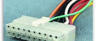
IMPORTANT: Be sure to take a photo of the power board with you to make the right purchase. Despite the fact that the blocks are almost identical, you need to be careful with the characteristics of the new parts.
Principle of operation
A switching power supply is distinguished by rectifying the mains voltage and then converting it to high-frequency voltage. It can drop to the required values, straighten and filter. First, the current passes to the bridge motor. The voltage limiter immediately acts (protects). Then it goes through filters, where it is transformed. Capacitors are needed to charge resistors. The node starts up after a breakdown of the dinistor. Later, the transistor is turned on in the power supply.
Article on the topic: How to set up channels on a Sony Bravia w70b TV
If generation occurs, the diodes will start working. They will be connected by cathodes. By means of a negative potential, the dinistor can be locked. In addition, there is a limitation. To prevent transistors from saturating, there are fuses that operate after a breakdown. To do the opposite, you need a transformer. At the output, the current exits through capacitors.
Load distribution on the power supply
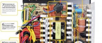
Since each power supply output voltage is used by a different load, depending on the computer configuration, the current consumption in each branch of the power supply may vary.
Therefore, for each block, in addition to the total maximum power, the maximum current consumption for each output voltage is also indicated.
Using the above photograph as an example, we will demonstrate the principle of calculating the applicability of a power supply:
- The 3.3V circuit has a maximum load current of 27A (89 W);
- A 5V circuit can deliver current up to 26A (130W);
- The 12V circuit is rated for current up to 18A (216 W).
But, since all these circuits are powered from the windings of a common transformer, their total consumption is limited: if in theory the maximum load at voltages of 3.3V and 5V can reach up to 219 W, it is limited to 195 W. With a maximum theoretical current output of all three circuits of 411 W, the actual load is limited to 280 W.
Thus, when adding new hardware to your PC, you need to consider not only the overall power consumption, but also the balance of the electrical circuits. Especially often, replacing power supplies with more powerful ones is required when installing high-performance video cards that significantly load the 12V circuit, while most of the PC power is taken from low-voltage circuits - the high voltage reserve remains insufficient.
Popular articles Bracelet made of pins
Power supply device, step-down mains voltage converter
Here is a selection of materials:
The practice of electronic circuit design. The art of device development. Element base. Typical schemes. Examples of finished devices. Detailed descriptions. Online payment. Opportunity to ask questions to the authors
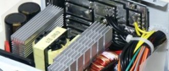
This power supply consists of high-voltage and low-voltage parts.
In the high-voltage part, the mains voltage is rectified and charges the filter capacitor. This results in a constant voltage of about 310 volts. Next, this voltage is converted into pseudo-rectangular oscillations with a frequency of 10 - 100 kHz, which allows, using small-sized pulse transformers, to be converted into low-voltage voltage with minimal losses.
In the low-voltage part, the incoming voltage with a frequency of 10 - 100 kHz is rectified, filtered and supplied to the load. In addition, there are control and feedback circuits that ensure the formation of the necessary signals and maintain the stability of the output voltage.
When looking at the power supply board, it is usually visually easy to understand where the high-voltage part is and where the low-voltage part is, since standards require that these parts be separated from each other by some distance in order to ensure user safety. The high-voltage part is where the mains wire goes. The low voltage part is where the load wires come from.
Most household devices contain switching power supplies built on the basis of two circuit solutions - half-bridge and single-cycle forward. See the diagram.
TV repair.
Chapter 1. Control and monitoring system for modern TVs (continued)
1.3. Central control device
1.3.1. Operating principle
1. Central control unit (CCU), which manages all information flows. Often this unit is made in one housing and is called a control microprocessor. 2. External storage device. 3. Receiver and decoder of IR remote control signals (IR processor).
External signals received by the control device can be commands from the remote control or from the control panel. In addition, pulse signals synchronized with the frequency of the lines and fields of the video signal, as well as signals to turn on the TV, are supplied to the control device.
The basis of the control device is a microcomputer or microprocessor (CPU), which, by executing a specific program, controls and distributes data flows and control signals. The CPU typically contains random access memory (RAM), a clock generator, and pins for connecting wires for data buses and individual instructions.
Depending on the configuration of the TV, one or more external ROMs of the following types are connected to the CPU:
- ROM - Read Only Memory - ROM containing data that cannot be changed. - PROM - Programmable ROM - PROM, which can be programmed only once. - EPROM - Erasable PROM - EPROM that can be erased and programmed again. - EEPROM - Electrical EPROM - EEPROM - repeatedly programmable ROM with electrical erasure.
Article on the topic: How to connect a TV to a Rostelecom router
The ROM stores the control program and various setting constants, such as:
— frame format; — brightness adjustment limits; — selection of programs; — transmission standard recognition; — menu table; — data group for each stored program; — service program; — a group of data used in case of emergency shutdown.
The control device may also contain a separate processor for processing signals coming from the remote control command receiver, the so-called IR processor.
Rice. 1.10. Block diagram of the central control unit
In Fig. Figure 1.10 shows an example block diagram of a central control device. It consists of:
1. Central (main) processor with internal memory. 2. External memory 1. 3. External memory 2. 4. IR processor.
Various operating constants are stored in storage devices. In this case, it is necessary to distinguish between basic setting data, which must always remain unchanged, and data entered by the user from the control panel or using the remote control. After switching on, the central processor receives operating data from the memory via the I2C bus, processes it and also transmits it via the I2C bus to the corresponding units to bring them to their original operating state.
The IR processor in the presented block diagram performs two functions:
1. Thanks to temporarily closed contacts in the power switch, it stores information about the state of the TV. Turning on occurs when the system reaches its initial state (reset), and the voltage level on the data and clock lines changes from high to low. After this, the power supply is turned on, all the necessary voltages are supplied, the IR processor signals that it is ready, and the initialization phase ends.
Article on the topic: When will the film be shown, move up on TV on which channel
2. Commands issued from the remote control are sent through an infrared receiver and preamplifier to the IR processor. Here they are processed and transmitted via a digital bus to the control device. Decoding of these instructions is carried out in the main processor.
Commands from the control panel are sent directly to the central processor and are decoded and processed here. These commands are usually switching channels, adjusting volume, brightness, contrast, etc.
The clock speed is usually generated in the main processor. Regardless of this, other clock frequencies are also required, which are generated in other blocks. The clock frequency outputs can be recognized by the external elements attached to them - special quartz resonators.
A necessary attribute of microprocessor circuits are reset circuits. They bring the processors to their initial state after turning on the power. The reset pulse (RESET) produced by these circuits can be positive or negative.
The general movement of information occurs along data lines of information buses. In addition, from the main processor, various enabling and regulating command signals are issued via separate lines - to various slave modules and nodes of the TV, signals for OSD circuits, etc. The main processor receives various control signals from the monitoring system for the operating modes of various nodes, according to which The main processor turns off the TV, particularly in emergency situations.
Many control devices are equipped only with an external memory for operating data and, instead of an IR processor, contain only an IR receiver. The working program in such devices is not as complete as that which is implemented in an external software memory.
Article on the topic: How to connect two TVs together
1.3.2. An example of a modern TV control module
The IC 1860 processor decodes the signals coming from the IR receiver IC1800 and transmits them over a 3-wire parallel bus to the main processor IC850. In addition, IC 1860 controls turning the power supply on and off by applying the required voltage to pin 2 of connector UB1, receives service information from the main processor IC850 via a 3-wire bus and displays this information on the display (DPI 840).
The main processor carries out system control of the entire TV. The constants necessary for the operation of the system, entered by the user during operation or by the technician during maintenance, are stored in the EEPROM IC840; the control program is in the IC860 ROM.
Initializing the TV when turned on
After starting the power supply, a +5 V voltage is supplied to the main processor IC850 and to the reset pulse driver circuit IC870, which, by applying a pulse to pin 15 of the IC850, returns the processor to its initial state and runs its control program stored in the IC860 ROM.
Rice. 1.11. Oscillograms of the TV control device GRUNDIG chassis CUC1822
Rice. 1.12. Timing diagrams of the information exchange process between IC850 and IC860
Transferring messages from the IC850 main processor to the IC1860 processor
The process is repeated until all eight bits have been transmitted (starting with the most significant bit).
1.3.3. Transferring messages from the remote control processor to the main processor
The process is repeated until all eight bits have been transmitted (starting with the most significant bit).
Article on the topic: How to connect a TV to a Rostelecom router
Timing diagrams of the information exchange process between the main processor IC850 and the remote control processor IC 1860 are presented in Fig. 1.12.
After turning on the TV using the button on the front panel, the main processor begins to execute the “I” program. Via the PC bus (28 and 29 pins of IC850), the processor receives the source data and setting constants for program “I” from the IC840 EEPROM. A separate program memory, the IC860 ROM, is used to store the extensive system control program.
Initial setup (reset)
If there is a low level on the RHO line, then the remote control processor, setting a high level on the PH1 line, keeps the power supply in the off state until a command from the remote control “0” is received at its PH2 input. “9” or AV, or P+. And as soon as a high level is established on the CLK, DATA and ACK lines, the remote control processor sends a message to the main processor about resetting to the initial state.
The system (main) processor IC850 resets as soon as +5V is available from the main power supply. After this, the program sequence starts as described earlier.
IC840 EEPROM Contents
IC850 Processor EPROM Contents
Data set for each of the 99 program positions
Service mode
Once powered up, the IC850 processor loads operating data from internal memory and the I2C bus from the IC840 ROM, and then transfers it via the I2C bus to the IC 1410 scan processor and other devices connected to the I2C bus.
Article on the topic: When will the film be shown, move up on TV on which channel
Geometric image parameters (such as vertical and horizontal size, geometric distortion correction, etc.) are stored in the internal EPROM of the IC850 processor. All other basic constants that cannot be changed during operation or repair are read by the processor from the external ROM IC860 and are part of the system control program. The IC860 also contains geometry parameters that can be called up as emergency rough-in settings in the event that the IC850 main processor fails and needs to be replaced.
In addition, the IC860 ROM contains the division factor and fine tuning parameter values, which are transmitted via the I2C bus to the frequency synthesizer located in the tuner.
The data for switching the intermediate frequency module to the mode of receiving signals according to one of the current television standards is stored during the setup process for each program position.
The processor retrieves this data via the I2C bus from a separate EEPROM IC2301 located in the IF module, converts it and returns it to the IF module at the ADC inputs of IC2305 and IC2320. Since IC2305 and IC2320 are not connected to the SDA line, data is loaded into them via a special “ENA ZF” line. Depending on the information received at the input, DACs IC2305 and IC2320 generate analog signals that are supplied to varicaps connected to the frequency-setting circuits. Thus, the tuning frequency of the IF circuits changes in accordance with the received television standard. This type of data transfer occurs every time you switch programs.
Article on the topic: 15 inch TV how many centimeters
1.3.4. Control processor malfunctions
Supply voltage monitoring
Switch-on voltage monitoring
Clock control
The TV cannot start working if the clock generator oscillates missing or has a frequency that differs from the optimal value. Monitoring the amplitude, frequency and shape of clock oscillations should be carried out using an oscilloscope.
Data movement control
Often in TV receivers you can call up a self-diagnosis program. After pressing the key combination provided for this, the processor polls the units connected to the system bus. The faulty unit is indicated and the fault is corrected without further investigation. This troubleshooting feature should be used first.
If the memory in which the frame geometry data is located is faulty, and the processor does not receive this data when turned on, then in this case the processor turns to the so-called emergency data block so that television scans can still start in the event of such a malfunction.
Control processor blocking
The cause of the malfunction is that the processor supply voltage is much higher than the normal value. This voltage must be stabilized, and its increase even by 10% can cause a malfunction, so if it is increased, then the fault should be looked for in the power supply. In addition, the processor itself may be faulty, causing it to heat up. This can be easily checked by touching the processor housing with your finger. As long as the processor is not warmed up, the malfunction does not appear in any way. However, after some time of operation, more and more incorrect activations appear, until eventually it becomes completely impossible for the TV to function. The processor is hot.
Article on the topic: How to replace a TV on a VAZ 2110
Control processor looping
The cause of the malfunction is that the processor does not capture the information entering it. If the supply voltages and signal amplitudes are normal, then the processor must be replaced.
Memory fault in the control device
The source of such faults can be either a separate memory or a memory contained in the processor.