In the modern world, the development and obsolescence of personal computer components occurs very quickly. At the same time, one of the main components of a PC - the ATX form factor power supply - is practically has not changed its design for the last 15 years.
Consequently, the power supply of both an ultra-modern gaming computer and an old office PC work on the same principle and have common methods for diagnosing faults.
The material presented in this article can be applied to any personal computer power supply with a minimum of nuances.
Power supply device
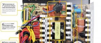
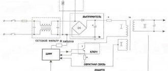
A typical ATX power supply circuit is shown in the figure. Structurally, it is a classic pulse unit on a TL494 PWM controller, triggered by a PS-ON (Power Switch On) signal from the motherboard. The rest of the time, until the PS-ON pin is pulled to ground, only the Standby Supply with a voltage of +5 V at the output is active.
Let's take a closer look at the structure of the ATX power supply. Its first element is a network rectifier :
Its task is to convert alternating current from the mains to direct current to power the PWM controller and standby power supply. Structurally, it consists of the following elements:
- Fuse F1 protects the wiring and the power supply itself from overload in the event of a power supply failure, leading to a sharp increase in current consumption and, as a consequence, to a critical increase in temperature that can lead to a fire.
- A protective thermistor is installed in the neutral circuit, which reduces the current surge when the power supply is connected to the network.
- Next, a noise filter is installed, consisting of several chokes ( L1, L2 ), capacitors ( C1, C2, C3, C4 ) and a counter-winding choke Tr1 . The need for such a filter is due to the significant level of interference that the pulse unit transmits to the power supply network - this interference is not only picked up by television and radio receivers, but in some cases can lead to the malfunction of sensitive equipment.
- A diode bridge is installed behind the filter, converting alternating current into pulsating direct current. Ripple is smoothed out by a capacitive-inductive filter.
Next, the constant voltage, present all the time while the ATX power supply is connected to the outlet, is supplied to the control circuits of the PWM controller and the standby power supply.
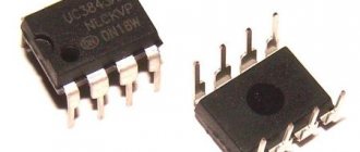
The standby power source is a low-power independent pulse converter based on transistor T11, which generates pulses through an isolation transformer and a half-wave rectifier on diode D24, feeding a low-power integrated voltage stabilizer on the 7805 chip. Although this circuit is, as they say, time-tested, it is not a significant drawback is the high voltage drop across the 7805 stabilizer, which leads to overheating under heavy load. For this reason, damage in the circuits powered from the standby source can lead to its failure and subsequent inability to turn on the computer.
The basis of the pulse converter is a PWM controller . This abbreviation has already been mentioned several times, but has not been deciphered. PWM is pulse width modulation, that is, changing the duration of voltage pulses at their constant amplitude and frequency. The task of the PWM unit, based on a specialized TL494 microcircuit or its functional analogues, is to convert DC voltage into pulses of the appropriate frequency, which, after an isolation transformer, are smoothed by output filters. Voltage stabilization at the output of the pulse converter is carried out by adjusting the duration of the pulses generated by the PWM controller.
An important advantage of such a voltage conversion circuit is also the ability to work with frequencies significantly higher than 50 Hz of the power supply. The higher the frequency of the current, the smaller the dimensions of the transformer core and the number of turns of the windings are required. That is why switching power supplies are much more compact and lighter than classical circuits with an input step-down transformer.
A circuit based on transistor T9 and the stages following it are responsible for turning on the ATX power supply. At the moment the power supply is turned on to the network, a 5V voltage is supplied to the base of the transistor through the current-limiting resistor R58 from the output of the standby power supply; at the moment the PS-ON wire is shorted to ground, the circuit starts the PWM controller TL494. In this case, failure of the standby power source will lead to uncertainty in the operation of the power supply starting circuit and a possible switching failure, as already mentioned.
Efficiency
Any device powered by an alternating current network has its own coefficient of performance (efficiency). Computer power supplies are no exception. Efficiency is the amount of energy that performs a useful function (powering a computer). Everything else is converted to heat. Currently there are efficiency levels presented in the table below
Advantages of high efficiency power supply:
- lower energy consumption compared to a power supply without appropriate certification. For example, a 500 W power supply with 80 Plus Gold certification (90% efficiency) and without certification (about 75% efficiency). At a load of 50% (250 W), a certified power supply will consume 277 W from the network, and a non-certified one will consume 333 W.
- Less heating since significantly less heat needs to be dissipated
- longer life of the power supply due to lower temperatures
- less noise, since a fan operating at lower speeds is required to remove a small amount of heat
- better power supply for components, hence more reliable and stable operation of the entire computer
- minimal distortion of power supply characteristics. Each device powered by AC power introduces its own interference. Certified power supplies use a special APFC (Active Power Factor Correction) device that increases efficiency and virtually eliminates interference from the computer power supply.
There is only one drawback - the price, which is more than compensated by the advantages.
Possible PSU malfunctions
The use of a proven pulse converter circuit for many years has made it extremely reliable .
Therefore, most PSU malfunctions in personal computers are associated either with the aging of its components, or with significant deviations of the power supply or load from the nominal parameters. Separately, it is worth mentioning the overheating of the output stages due to the accumulation of dust inside the power supply due to insufficient frequency of computer maintenance.
Aging has the greatest impact on the condition of the electrolytic capacitors of the rectifier and output stages. Over time, they degrade, losing capacity, which leads to a noticeable increase in voltage ripple at the output of the unit, which can lead to malfunctions of the PC. Also, especially in cheap units, the aging of electrolytic capacitors is accompanied by their noticeable swelling, sometimes leading to their destruction with a characteristic pop.
A significant increase in supply voltage or excessive load can lead to overheating and a short circuit inside the diode bridge of the input rectifier. In this case, alternating current from the network enters circuits that are not designed to work with it: electrolytic capacitors designed for unipolar power supply are destroyed, the PWM controller and its transistor wiring are damaged. Often, damage to the power supply makes its repair less cost-effective compared to a complete replacement.
Failure of the output transistors of a pulse converter is most often a consequence of their prolonged overheating caused by overload or insufficient cooling.
Definition and purpose
According to the technical definition, a power supply is an electrical device designed to generate supply voltages. PSU is a secondary power source.
Open the technical documentation and read. The secondary power supply converts the electrical parameters of the main power supply source, for example, an industrial network, into electrical power with the parameters necessary for the operation of auxiliary devices.
We conclude: the purpose of the power supply is to provide devices powered by electricity with voltage with the specified parameters necessary for their operation.
Important! If the device requires several different voltages (for example, a PC), then the power supply has several output channels - each with its own value.
Checking the power supply
Although a pulse power supply is not an entry-level radio-electronic circuit, its DIY diagnostics and repairs are accessible to many people who have basic knowledge and skills in the field of radio electronics. Let's consider a typical procedure for checking a power supply removed from a computer:
- Connect powerful load resistors rated for a current of about 1A and the corresponding power to the +3.3V, +5V and +12V terminals. This is necessary to avoid incorrect operation of some units without load.
- Apply mains power to the unit.
- Check for voltage on the +5VSB line. It should occur immediately after the block is connected to the network.
- Connect the PS-ON terminal to the power supply housing. In this case, the corresponding voltages must be set at the power outputs of the power supply unit and the PG output.
Possible faults :
- There is no standby voltage when the power is turned on. If the power supply starts up and generates controlled voltages, check the operation of the standby voltage pulse converter (the presence of pulses on the primary winding of its transformer), the serviceability of the rectifier (the presence of a constant voltage of at least 9V at the input of the 7805 microcircuit) and the operation of the stabilizer (the output of the 7805 microcircuit should be +5V).
- If there is standby voltage, but the power supply does not start, try to force the PWM controller to start as follows:
- If there is no generation of pulses on the indicated legs of the microcircuit, it will need to be replaced. Otherwise, you should pay attention to the output stage of the converter, especially the switching transistors.
- If there is no standby voltage and the power supply does not start, check the input rectifier sequentially: the integrity of the fuse and thermistor, the absence of breaks in the inductor windings. However, the most common malfunction is the burnout of the diode bridge as a result of a short circuit in the filter capacitor. This will be immediately noticeable both by the characteristic smell and by the burnt diodes.
- If there is no voltage at only one of the controlled power outputs, you should first of all pay attention to the rectifier diode and filter capacitor of this circuit.
Power Factor Correction
The PFC module allows you to significantly increase the efficiency (“bepeshnik”), which in Russian means “power factor correction.” The PFC module is a special element designed for power factor correction and aimed at protecting the network. PFC is conventionally divided into active (Active) and passive (Passive).
We recommend buying power supplies with PFC (they allow you to achieve a high level of efficiency - up to 95%), and active ones, because APFC additionally equalizes the input voltage, which in turn allows all devices that output an analog signal from the computer to operate stably.
Note that APFC models are slightly more expensive than their passive counterparts, but the difference in efficiency will later be reflected in your energy bills.
Power supply repair
If you have sufficient confidence in using a soldering iron, repairing a power supply with your own hands is not so difficult , especially since most operations come down to replacing simple parts with two or three pins that do not require special skills or equipment for dismantling.
Since the question “how to repair a computer power supply” is unlikely to arise for a person who professionally owns the appropriate tool (soldering station, desoldering pump, etc.), in the future we will proceed from the minimum set of the most common devices. Therefore, we will need a soldering iron with a power of around 65 W with a flat tip, solder, acid-free flux (rosin), tweezers and a flat-head screwdriver. Excess solder can be removed using stripped stranded copper wire submerged into a drop of molten tin.
When replacing large-sized elements like capacitors, you need to sequentially heat the soldering points of their legs, remove excess solder if possible, and then either alternately warm up the legs and tilt the capacitor body from side to side to remove it, or, if the size of the soldering iron tip allows this, heat both points simultaneously solder and quickly pull the capacitor out of the holes in the board. In this case, as when working with other elements, it is important to minimize the time the soldering iron is exposed to the board and the part.
When replacing transistors and powerful diodes, they are installed in the holes on the board so that the mounting hole coincides with the threads in the radiator body. Before attaching to the radiator, the surface of the part is lubricated with thermal conductive paste (KPT-8 or its analogues).
When replacing an electrolytic capacitor or diode, you must remember that these are polar elements, and their installation must strictly correspond to the drawing on the board (for capacitors, except tantalum, the strip indicates the negative pole).
Another material about computer power supply repair
After repairing the power supply,
you should not rush to install it in the computer - it is best to repeat the check described earlier.
Efficiency Efficiency
High power in itself does not guarantee high-quality work. In addition to it, other parameters are also important, for example, efficiency. This indicator indicates what share of the energy consumed by the power supply from the electrical network goes to the computer components. The higher the efficiency, the less the power supply heats up (and there is no need for enhanced cooling using a noisy fan), i.e. more efficiently converts the energy from the electrical outlet into the stated watts and, of course, the less energy is wasted on heating. For example, if it is 60%, then 40% of the energy is floating around your room (catch it :-)).
The “efficiency” of the power supply is assessed by its system of medals - the “80 PLUS” standard.
This standard has several performance levels: Platinum, Gold, Silver and Bronze, and the specifications for each have their own set of requirements. Of course, “80 PLUS Platinum” or “80 PLUS Gold” power supplies will be more efficient (90% efficiency or higher) than their regular counterparts, but they also cost more. Therefore, it is better to use the rule here - choose a model with “80 PLUS” certification, and select the “medal” level based on your budget (but not lower than bronze).
Scheme
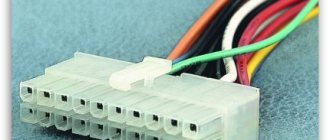
Diagram No. 2 “power cable connector - device connector”
With scheme No. 1 everything is clear. Each cable has its own connector.
Scheme No. 2 also does not cause difficulties - it is a more understandable version of the first, but we will still analyze it. So (moving from 1 to 5):
- A cable with this connector is connected to the motherboard. Depending on the board type, it is equipped with 20 or 24 pins;
- Modern processors usually require additional power. A separate cable from the power supply is intended for this;
- Powerful video cards also require additional power. For this purpose, one or two connectors with 6 or 8 pins are used;
- Disk devices with an IDE interface and case fans are connected to the power supply using 4-pin Molex connectors;
- SATA hard drives and optical drives use a different type of connector to receive power.
That's all, we figured out the connection. You see, it’s not so difficult if you know the topology of the connectors and the basic connection rules, and you now know them.
So, cross your fingers, now you can not only choose the “right” power supply, but also connect it, and therefore breathe life into your “hardware” (:-)).
Thus, you have moved from the level of “who should I ask and should I call a specialist?” to a qualitatively new level of “why! I’ll do everything myself.” Congratulations!
What is PFC?
Another important parameter of any power supply is the type of PFC (Power Factor Correction), that is, what type of power factor correction it uses. There are active and passive PFCs.
Let's start with the first: Active PFC is, in fact, an additional switching power supply that increases the voltage. In this mode, the power supply receives power from the power grid in short pulses. This has a good effect on reducing high-frequency interference and helps work with analog video and audio. However, in a gaming PC this is generally useless, and besides, active PFC reduces the power factor.
There are many excellent power supplies with active PFC, so if you do not live in a village with old electrical networks, then feel free to take them. There are many excellent power supplies with active PFC, so if you do not live in a village with old electrical networks, then feel free to take them
Therefore, if you mainly use your computer for gaming, then feel free to buy a power supply with passive PFC. You won’t notice the difference, but you will slightly increase the efficiency of the power supply, which means you will save money on electricity. As they say, it’s a small thing, but it’s nice.
However, it’s also not worth “killing yourself” because of PFC, giving up an otherwise excellent power supply. For example, but many models from be quiet! There is an active PFC, and this does not mean that these power supplies are bad.
Dimensions
When specifying the dimensions of a power supply, manufacturers, as a rule, limit themselves to designating the form factor, which must meet the ATX 2.X standard. See this on the power supply itself (arrow 1 in the image) or on the documentation that came with it. Also, when purchasing, we recommend comparing its dimensions with the dimensions of the “seat” in your PC case
Please note that if the case bears the inscription “noise killer” (arrow 2 in the image), then the fan rotates as slowly as possible, which reduces the sound level. The rotation speed is regulated by a special temperature sensor
The old power supply (AT standard), which turns the computer on and off using a regular power switch, is far from the best option. Nowadays, its purchase can only be justified by the fact that you have an “ancient” machine at home, into which it is physically impossible to insert a more modern module.
It is better to choose an ATX device that works only after a command from the motherboard. This technology makes it possible to remove the high-voltage wire from the unit and improve safety. Even if the ATX unit burns out, the likelihood that something else will be damaged is much lower. In turn, the ATX standard has several different modifications. ATX version 2.03 is available for powerful computers with high energy consumption.