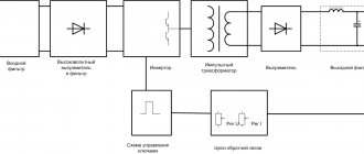
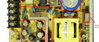
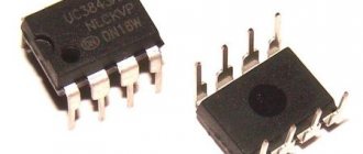
This stabilizer has good characteristics, has smooth adjustment of current and voltage, good stabilization, tolerates short circuits without problems, is relatively simple and does not require large financial costs. It has high efficiency due to the pulse operating principle; the output current can reach up to 15 amperes, which will allow you to build a powerful charger and power supply with adjustable current and voltage. If desired, you can increase the output current to 20 amperes or more.
On the Internet of similar devices, each has its own advantages and disadvantages, but their operating principle is the same. The proposed option is an attempt to create a simple and fairly powerful stabilizer.
Through the use of field switches, it was possible to significantly increase the load capacity of the source and reduce heating on the power switches. With an output current of up to 4 amperes, transistors and a power diode do not need to be installed on radiators.
The ratings of some components on the diagram may differ from the ratings on the board, because I developed the board for my own needs.
The output voltage adjustment range is from 2 to 28 volts, in my case the maximum voltage is 22 volts, because I used low-voltage switches and raising the voltage above this value was risky, but with an input voltage of about 30 Volts, you can easily get up to 28 Volts at the output. The output current adjustment range is from 60mA to 15A Ampere, depending on the resistance of the current sensor and the power elements of the circuit.
The device is not afraid of short circuits, the current limit will simply work.
A source is assembled based on the TL494 , the output of the microcircuit is supplemented with a driver for controlling power switches.
I would like to draw your attention to the bank of capacitors installed at the output. Capacitors with low internal resistance of 40-50 volts should be used, with a total capacitance of 3000 to 5000 μF.
A load resistor at the output is used to quickly discharge the output capacitors; without it, the measuring voltmeter at the output will work with a delay, because When the output voltage decreases, the capacitors need time to discharge, and this resistor will quickly discharge them. The resistance of this resistor must be recalculated if a voltage greater than 24 volts is applied to the input of the circuit. The resistor is two-watt, designed with a power reserve, it can get warm during operation, this is normal.
How it works:
The PWM controller generates control pulses for power switches. If there is a control pulse, the transistor and power through the open channel of the transistor through the inductor is supplied to the storage capacitor. Do not forget that the inductor is an inductive load, which tends to accumulate energy and output due to self-induction. When the transistor closes, the charge accumulated in the inductor will continue to feed the load through the Schottky diode. In this case, the diode will open, because The voltage from the inductor has reverse polarity. This process will repeat tens of thousands of times per second, depending on the operating frequency of the PWM chip. In fact, the PWM controller always monitors the voltage on the output capacitor.
Stabilization of the output voltage occurs as follows. The non-inverting input of the first error amplifier of the microcircuit (pin 1) receives the output voltage of the stabilizer, where it is compared with the reference voltage that is present at the inverse input of the error amplifier. As the output voltage decreases, the voltage at pin 1 will also decrease, and if it is less than the reference voltage, the PWM controller will increase the pulse duration, therefore the transistors will be in the open state for more time and more current will be pumped into the inductor, if the output voltage is greater than the reference , the opposite will happen - the microcircuit will reduce the duration of the control pulses. The specified divider can forcefully change the voltage at the non-inverting input of the error amplifier, thereby increasing or decreasing the output voltage of the stabilizer as a whole. For the most accurate voltage regulation, a tuning multi-turn resistor is used, although a regular one can be used.
The minimum output voltage is about 2 volts, set by the specified divider; if you wish, you can play with the resistance of the resistors to obtain acceptable values for you; it is not recommended to reduce the minimum voltage below 1 volt.
A shunt is installed to monitor the current consumed by the load. To organize the current limiting function, a second error amplifier is used as part of the Tl494 PWM controller. The voltage drop across the shunt is fed to the non-inverting input of the second error amplifier, again compared with the reference one, and then exactly the same thing happens as in the case of voltage stabilization. The specified resistor can regulate the output current.
The current shunt is made of two parallel-connected low-resistance resistors with a resistance of 0.05 Ohm.
The storage choke is wound on a yellow-white ring from the group stabilization filter of the computer power supply.
Since the circuit was planned for a fairly large input current, it is advisable to use two rings folded together. The inductor winding contains 20 turns of 1.25 mm diameter wire wound in two strands in varnish insulation, the inductance is about 80-90 microhenry.
It is advisable to use a diode with a Schottky barrier and a reverse voltage of 100-200 volts; in my case, a powerful MBR4060 of 60 volts 40 Amps was used.
The power switches together with the diode are installed on a common radiator; however, there is no need to isolate the component substrates from the radiator, because they are common.
A detailed description and testing of the unit can be seen in the video
PCB here
Laboratory power supply from a computer unit on TL494
Date: 02.23.2018 //
Today we have a mixed note. Many will consider this article unclaimed, but this material is intended primarily for beginners who want to assemble a simple laboratory power supply from a computer unit on the TL494.
Poking around the board of an old PC power supply, changing feedback loops and removing unnecessary parts, there is always a risk of removing something unnecessary. If you make a mistake while installing the board, there is practically no chance of getting a usable device, only the risk of permanently burning the block increases many times over.
After thinking a little about how you can easily make a laboratory power supply with your own hands, we created an adapter for PWM TL494 to the same TL494 . It sounds a little stupid, but the adapter includes a PWM with a new harness that is already routed to control the output voltage and current, and there is absolutely no need to tinker with the block itself. It is enough to remove the microcircuit, install and connect the adapter - the laboratory unit is almost ready.
Original circuit
First, the original unipolar circuit was assembled to test and search for possible errors, which some who assembled this design wrote about. Everything worked fine for me right away, the only issues I had were with adjusting the limiting current and indicating when this limit was triggered.
Next, a similar circuit was assembled for a voltage of negative polarity - completely similar, only with a change in the polarity of the inclusion of electrolytic capacitors, diodes (zener diodes) and using transistors of the opposite structure (npn / pnp). The designations of the elements of the “minus” arm are left the same as those of the “plus” one to simplify drawing the diagram
. one year later.
Looking through the datasheet for the KA7500 chip (analogous to TL-494), I discovered another, simpler solution for stabilizing the power supply current. The authors suggest using a second comparator (pins 15,16). Considering that this comparator is initially biased by 80 mV, this creates a very convenient solution. I repeated it twice. In the given circuit, the output voltage is 18 volts, the current is 5 amperes to power the dog house heating circuit. To charge batteries, of course, you can use the unit without rewinding, but it’s still better to rewind. And it is advisable to take a thicker wire and add more turns.
When calculating the number of turns of the secondary winding, it is desirable that at XX the voltage at the bridge output should be approximately 2 times higher than the stabilized one. This will ensure optimal PWM and, accordingly, reliable stabilization.
It's strange, but it works. But in general it shouldn’t. It shouldn’t because the offset of 80 mV is indicated in some datasheets, but not in others. In general, this offset is not enough for stable operation. So I prototyped a similar OS on “spokes” and this is what happened.
For ease of prototyping, I chose the LM311 comparator. I applied a reference voltage of 1 volt to the 16th leg (according to TL-494). Now everything is beautiful. The comparator operates at 6.1 Amperes. The red beam is the output of the comparator, and the green beam is the current through the load (R3). Yes, and a 0.15 Ohm resistor is easier to make and will heat up less than 0.3. Then the scheme changes a bit.
Rewinding transformers (rewinded 5 of them) has never caused me any problems. I just heat it in the closet to 150 - 200 degrees and carefully loosen it with gloves.
RESULTS 4.
12 0 RESULTS ¾Ð½ÑÑÑÑкÑÐ¾Ñ Ð¼Ð¸ÐºÑоÑÑÐµÐ¼Ñ Ð¿ÑедÑÑмоÑеÐ" иÑп¾Ð"Ñз › › › ни". ROOM › › › › › › › › › › аÑиÑ. RESULTS. RESULTS. RESULTS. RESULTS +5 +5 +5 +5 +5 +5 +5 +5 ÑÑ, ÑÑо наглÑÑо закÑÐ²Ð°ÐµÑ Ð²ÑÑоднÑе клÑÑи Ð¼Ð¸ÐºÑ Ð¾ÑÑемÑ. ( 4-емлÑ) и на вÑводе 4 напÑÑжение RESULTS. RESULTS › › › SOLUTION ±response. 4 points ROOM ¾ Ñока. RESULTS 1/2 (4 points 0.22 оÑм), оÑкÑÑваеÑÑÑ ÑÑанзиÑÑÐ¾Ñ 733 ( pnp _
Ñ Ð¼ÐµÐ½Ñ Ð±ÑÐиз вÑп°ÑннÑÑ), ÑÑо пÑÐ¸Ð²Ð¾Ð´Ð¸Ñ Ðº подÑÑ 4 Ð¼Ñ Ð½Ð°Ð¿ÑÑÐ¶ÐµÐ½Ð¸Ñ Ð½Ð° вÑводе Ñак до Ñежима ÑÑабилизаÑии Ñока. RESPONSIBILITY RESULTS. RESULTS ½Ð¾Ð³Ð¾ Ñока заÑÑдки и заÑи ÑÑ Ð¾Ñ ÐºÐ¾ÑоÑкого замÑÐºÐ°Ð½Ð¸Ñ Ð½Ð° вÑÑоде. ÐÑаÑи, RESULTS Ð¸Ñ ÐºÐ¾Ð½Ð´ енÑаÑоÑов не ÑÑавиÑÑ, Ñогда пÑи “коÑоÑком” н RESULTS ¸Ñ непÑиÑÑнÑе оÑÑÑениÑ.
List of elements.
R1 = 2.2 kOhm 1W R2 = 82 Ohm 1/4W R3 = 220 Ohm 1/4W R4 = 4.7 kOhm 1/4W R5, R6, R13, R20, R21 = 10 kOhm 1/4W R7 = 0.47 Ohm 5W R8, R11 = 27 kOhm 1/4W R9, R19 = 2.2 kOhm 1/4W R10 = 270 kOhm 1/4W R12, R18 = 56 kOhm 1/4W R14 = 1.5 kOhm 1/4W R15, R16 = 1 kOhm 1/4W R17 = 33 Ohm 1/4W R22 = 3.9 kOhm 1/4W RV1 = 100K trimmer P1, P2 = 10KOhm linear potentiometer C1 = 3300 uF/50V electrolytic C2, C3 = 47uF/50V electrolytic C4 = 100nF polyester C5 = 200nF polyester C6 = 100pF ceramic C7 = 10uF/50V electrolytic C8 = 330pF ceramic C9 = 100pF ceramic D1, D2, D3, D4 = 1N5402,3,4 diode 2A - RAX GI837U D5, D6 = 1N4148 D7, D8 = 5.6V Zener D9, D10 = 1N4148 D11 = 1N4001 diode 1A Q1 = BC548, NPN transistor or BC547 Q2 = 2N2219 NPN transistor - (Replace with KT961A - everything works) Q3 = BC557, PNP transistor or BC327 Q4 = 2N3055 NPN power transistor (replace with KT 827A) U1, U2, U3 = TL081, op. amplifier D12 = LED diode
As a result, I assembled a laboratory power supply myself, but in practice I encountered something that I considered necessary to correct. Well, firstly, this is the power transistor Q4 = 2N3055; it must be urgently crossed out and forgotten. I don’t know about other devices, but it is not suitable for this regulated power supply. The fact is that this type of transistor fails instantly if there is a short circuit and the current of 3 amperes does not draw at all!!! I didn’t know what was wrong until I changed it to our native Soviet KT 827 A. After installing it on the radiator, I didn’t know any grief and never returned to this issue.
As for the rest of the circuitry and parts, there are no difficulties. With the exception of the transformer, we had to wind it. Well, this is purely out of greed, half a bucket of them is in the corner - don’t buy it =))
Well, in order not to break the good old tradition, I am posting the result of my work for the general court, I had to play around with the column, but overall it turned out not bad:
The front panel itself - I moved the potentiometers to the left side, on the right side there was an ammeter and a voltmeter + a red LED to indicate the current limit.
The next photo shows the rear view. Here I wanted to show a method for installing a cooler with a radiator from a motherboard. A power transistor is placed on the back side of this radiator.
Here it is, the KT 827 A power transistor. Mounted on the rear wall. I had to drill holes for the legs, lubricate all contact parts with heat-conducting paste and secure them with nuts.
Here they are....the insides! Actually everything is in a heap!
Slightly larger inside the body
Front panel on the other side
Taking a closer look, you can see how the power transistor and transformer are mounted.
Power supply board on top; Here I cheated and packed low-power transistors at the bottom of the board. They are not visible here, so don't be surprised if you don't find them.
Here is the transformer. I rewound it to 25 volts of the TVS-250 output voltage. Rough, sour, not aesthetically pleasing, but everything works like a clock =) I didn’t use the second part. Left room for creativity.
Somehow like this. A little creativity and patience. The unit has been working great for 2 years now. To write this article I had to disassemble it and reassemble it. It's just awful! But everything is for you, dear readers!
There is nothing better than seeing once than hearing 100 times, it’s nice to share such a video, video of assembly and test of the power supply:
First you need to get the block working
In order for “dummies” about restoring blocks, general rules:
- If the fuse is OK, go to step 4.
- If the fuse is blown, then first check that there is no “short” on the connector
220.
- If it is “short”, we eliminate it; it could be power transistors, diodes, capacitors. At the same time, I advise you to check the diodes in the secondary circuit.
- After eliminating the “short”, unsolder the fuse and solder the “crib” in its place, if it was not installed during manufacture.
- Instead of a fuse, we insert into the “crib” a pre-prepared resistor made from a burnt-out fuse and a 220-volt light bulb with a power of 100-200 watts.
- It’s better if you have an isolation transformer, but if not, it’s not very scary. It is enough just not to stick your fingers into the power half of the block. We turn on the unit at 220. We close the “green” and “black” wires on the large connector. If there is no load, a working ATX will spin its blades trying to take off. The light bulb (fuse) should not light up. If so, you can insert a fuse instead of the light bulb and begin remaking the unit, but it is better to leave the light bulb for now.
- If the light does not light up but the ATX does not “rise”, check the presence of power to the TL-494 microcircuit (or its equivalent). If another microcircuit is used in the block, you don’t have to read further, or read out of curiosity. So, on the 12th leg of the microcircuit (relative to the 7th) we check the presence of standby power from 5 to 25 volts. If there is no power, then the standby power supply, referred to in different sources as +USB, “standby”, etc., is not working. If there is no +USB, there are 3 ways: look for a malfunction in the control room, power the TL494 from any other power supply (adapter), or go to the nearest workshop and buy (ask) another ATX. The fact is that the “duty room” is relatively difficult to repair. Usually, after replacing the transistor or Viper, or something else, the malfunction soon recurs. The problem is not so much the difficulty of troubleshooting, but the faults themselves. This may be an interturn in the pulse transformer, an insufficiently “fast” electrolytic capacitor in the secondary circuit, a loss of inductance of the inductor in the secondary circuit (due to overheating of the ferrite), a break in the starting current resistor of the “standby” and much more, which is quite difficult to establish having under control hands only tester. But I wish good luck to those who are more patient.
- A few words about the AT block. The fact is that ATs rise without a “duty man”. And without any help at all. In this sense, they are more tenacious and, if I may take liberty, more perfect. Thanks to some tricks in the circuitry of the power “half-bridge”, the unit begins to “sob” completely independently, without any “duties” or microcircuits. At this moment, the TL-494 power capacitor is charged from the 12-volt winding through a separate diode (green arrow in the diagram). Usually 1-2 “sobs” and the AT rises, continuing to power the TL-494 along the same circuit as in the ATX. In the ATX, after switching on, the TL-494 is powered from the “duty room”, then the power rises and, as in the AT, is supplied from +12 volts. In both cases, the supply capacitor is charged to a peak voltage value of approximately +24 volts.
