In many apartments in our country you can find voltage stabilizers from Resanta, which is understandable. This is due to the fact that such units allow you to normalize the operation of all electrical appliances that are present at home. In other words, they allow you to save quite expensive equipment in the event of an overload in the network or during power surges, thereby significantly extending the service life of all electrical equipment.
However, the operation of a voltage stabilizer is also associated with the risk of certain breakdowns, the only way out of which is
timely repair .
There may be several reasons for this - from improper operation to natural causes of breakdown, i.e. long service life.
To avoid this, you must strictly follow the instructions included in the kit, which will significantly extend the service life of the unit in the correct operating mode. If a breakdown does occur, then you need to know what methods you need to properly carry out repairs yourself, so as not to further aggravate the situation. In this article we will look at the main faults, as well as ways to eliminate them in a timely manner.
This video shows a Resanta stabilizer with a malfunction
Operating principle of rectifiers
The operating principle of devices differs depending on their type, power and a number of other characteristics. The design of Resanta rectifiers includes the following elements:
- The electronic unit.
- Transformers of automatic type.
- Controls.
- Voltmeter.
The schematic diagram of the Resanta 5000W stabilizer includes an electronic unit, which is responsible for controlling the operation of the power part of the unit.
The main module receives data on the power of the input voltage from the voltmeter, after which the automation checks the received figures with the established optimal values, making appropriate adjustments. The output is high-quality electric current with equalized amplitude. Voltage surges, which can damage operating equipment and household appliances, are completely eliminated. Depending on the type of transformer, the method of disconnecting and starting them, it is customary to distinguish two types of stabilizers:
- Relay.
- Electromechanical.
The most popular today are electromechanical type stabilizers, the design of which includes a servo drive that is responsible for turning off and starting the winding in the device.
The drive includes a low-power motor on which the contact brush is located. The advantages of electromechanical type stabilizers include their accuracy of operation, as well as a wide range of voltage adjustment. The only drawback is the complexity of the design, which negatively affects the reliability of the equipment. In relay stabilizers, built-in automation disconnects and connects the turns of the work switch until the optimal output voltage is obtained. To speed up the operation of the device, all turns of the transformer are divided into subgroups, which makes it possible to improve the voltage amplitude, while simplifying the operation of the device. Stabilizers of this type are reliable, which is explained by the simplicity of their design. The disadvantages include the low speed of voltage rectification, so it is not recommended to use them with sensitive devices.
Customer Reviews
The products manufactured by the company have too wide a model range, therefore there are quite a lot of different reviews on the purchased devices. But to put it briefly, purchasing products from this brand is fully justified due to its good technical characteristics.
Even long-term operation of the equipment does not affect the equipment; technical parameters remain at the same high level. In addition, buyers note the stylish design and reliability of the metal cases of Resanta products.
There is no 220 Volt output
The malfunction manifests itself in the fact that the stabilizer does not produce a voltage of 220 Volts. This does not necessarily indicate internal problems, the reason may be the mains voltage - it is too low, and the device simply does not pull. If the power is in the operating range of the stabilizer, then we will proceed with the repair.
What to do:
in servo-driven models, failure may be caused by wear of the brush mechanism or the servo drive itself. It may not reach the end of the winding or the brush may not be in contact with its corresponding sector. In the simplest case, it may simply be contaminated with graphite. To repair it, you need to clean the surface of the contacts to a metallic shine. Sometimes you need to replace the brush.
Interesting!
It also happens that due to contamination of the working sector of the brush assembly with graphite, the voltage often does not rise above a certain value.
In relay MVs, this most often indicates that one or more electromagnetic relays or their control cascade is faulty. It is usually built on a transistor. Relays can have different coil voltages, often 12 volts.
What to do:
To check, apply voltage to the coil and ring the power contacts. They should close and open, the relay clicks. If this does not happen, either the contacts have stuck (more often), or the relay coil has burned out (less often). If the relay is working properly, check the transistor; it should not be broken, and the emitter-base and collector-base junctions should ring in one direction, like a diode. Use any low-power transistors of similar conductivity.
In triac and thyristor MVs, the fault diagnosis is similar - you need to test the semiconductor power switch for breakdown and, if it fails, replace it with an analogous or more powerful one.
Shuts down under load
The voltage stabilizer does not support the load - this problem happens for a number of reasons. The first among them is increased load (consumer power). If you have not changed the connected devices, then the problem is in the stabilizer. If it does not turn off instantly, but after some time of operation, then this may be due to overheating or interturn short circuits of the autotransformer.
What to do: disassemble the device and carry out an external inspection of the windings of the autotransformer; if it is not too dusty, then check for signs of local overheating. If there is a lot of dust, clean it out
If there are signs of overheating and burning, the insulation of the windings is damaged. This is an interturn short circuit, then how to repair the stabilizer in this case? It is necessary to rewind or replace the autotransformer with one of the same or greater power. But the cost of such repairs can be comparable to purchasing a new voltage stabilizer.
Important! In servo-drive models, a number of malfunctions can be caused by brush wear and contamination of live parts with graphite shavings. During operation, the brush wears off, covering the autotransformer with graphite. Because of this, short circuits between current collectors and sections of turns and overheating can occur. In this case, you need to sweep away the graphite and clean it between turns. Make sure that the windings are laid evenly and there are no breaks. Clean the contact surface with a regular office eraser until it shines, especially the most used sector.
Repair
Repair of the Resanta stabilizer can be divided according to the type of breakdown.
Servo
First, let's look at a situation where the Resant servo motor fails. There are two ways out of this problem:
- Buy a new motor, then install it in the device.
- Try to repair the damaged one.
If everything is clear with the first case, then the second requires detailed consideration.
It is important to understand that if the repair work is successful, the restored engine will not be able to work for a long time, i.e. this is a temporary measure
All our actions will boil down to the following:
- We disconnect the motor with the servo drive from the overall structure. Then we connect it to a power source with sufficient power.
- It is necessary to supply a current of 5 V to the motor outputs. The current must be at least 90 mA.
- Carrying out these manipulations will normalize the operation of the stabilizer. Next you need to connect the motor back to the circuit.
The circuit is quite simple: the input cable is connected to the input terminal, the neutral cable is connected to the neutral terminal. The same manipulations are performed for the output cables. In addition, you need to remember to connect the ground wire.
Relay
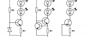
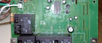
Failure of a relay often leads to breakdown of transistors. For example, in the ASN-5000 model, transistors of the D882P type are located. The diagram is shown below:
If these transistors fail, then you need to purchase new ones to replace them. You can purchase them quite freely, because many specialized stores sell Resanta brand equipment and components.
You can also try to repair damaged parts:
- First you need to remove the relay cover. Next, remove the moving contact, freeing it from the spring.
- Using sandpaper, remove all carbon deposits from the contact. We carry out this manipulation for both contacts - upper and lower.
- Then we lubricate the contacts with gasoline, after which we assemble the relay structure.
Other faults
Another possible problem is that the display turns on randomly, as well as the relay itself turns on. The reason for this may be the XTA1 resonator, which may have been soldered incorrectly.
The repair is as follows:
- Solder this resonator using a soldering iron.
- Use sandpaper to clean the leads.
- Solder the resonator back.
A specialist's story about the repair of Resant
Relay damage
In transistor modifications of Resant, the relay often breaks, which limits the functionality of the device or completely disables it. Relay repair will directly depend on the nature of the breakdown. In most cases, it is necessary to identify failed transistors and replace them with new ones.
Do-it-yourself repair of the Resanta voltage stabilizer is carried out as follows:
- Remove the relay cover, dismantle the moving contact and release the retaining springs.
- Using fine sandpaper, carefully clean the upper and lower contacts.
- Connections and contacts are carefully lubricated with gasoline.
- The relay design is assembled in the reverse order.
Such repairs are possible in cases where oxidation of the relay contacts is noted. All work can be done independently, without the use of voltmeters and other professional equipment.
Features of operation of an electromechanical device
First we will look at the electromechanical normalizer. The design of this voltage stabilizer provides for the presence of such an element as a servo drive. Actually, thanks to it, the different windings of the automatic transformer are switched.
Switching of these windings is carried out smoothly and as a result, precise regulation of the output voltage is ensured.
How does this smooth adjustment occur? A servo consists of a motor and a brush (electrical contact) that is attached to the motor's armature. When this anchor rotates, the brush also moves. It is constantly in contact with the copper windings of the transformer.
In fact, she glides along them. It has a width that allows you to connect two windings at the same time. As a result, no phase is lost at the output.
In order for the brush to move in a certain direction and by a certain amount, an error voltage is created in the normalizer. Further, thanks to the operational amplifier and the transistor output stage (it is a power amplifier), this voltage is amplified.
After this, it is supplied to the engine and causes the armature to spin in a certain direction.
The brush, which is in contact with the windings, also moves in this direction. The error voltage is proportional to a value that is the difference between the number of volts at the input and the required number of volts.
The error signal can have one of two polarities and as a result, each polarity causes the motor axis to rotate in a certain direction. These are the features of the operation of the electromechanical normalizer.
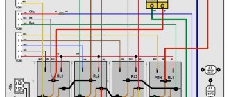
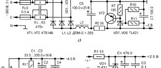
Note that many people buy a 10-kilovolt-ampere electromechanical stabilizer. Therefore, possible malfunctions and breakdowns of this type of voltage stabilizer will be considered on this model. Below is its electrical diagram.
Rice. 1. Electrical circuit of the ASN-10000/1-EM stabilizer.
It is worth paying attention to the fact that the general structure of all normalizers of this type is similar. The differences lie in individual elements of the models with different power levels
The lineup
I would like to consider several models of Resanta stabilizers (the company’s catalog is quite large), which are especially popular. These are Resanta ASN-500/1-C, ASN-1000, ASN 5000 and ASN 10000.
Why is there such a big spread? Firstly, all numerical values, which are 500, 1000, 5000, and 10000, indicate the power of the device. But there is one trick here. If Resanta ASN-500 is a low-power device with a power consumption of 500 W, which also applies to the indicator 1000. Then ASN 5000 and ASN 10000 are power with the unit of measurement “VA”. If we convert, for example, 10 kVA into kilowatts, then this figure will be equal to 10 kW, it will be equal to 8 kW.
The machine does not turn on or crashes after the timer report
Most stabilizers do not enter operating mode immediately after switching on, but after a temporary delay. But after the report, the start-up timer does not occur, and the display indicator shows the letter N. An example of repairing a device with such a malfunction is discussed in the following videos:
For your information, the error code “H” indicates that the network voltage is too high and the protection has tripped. This is valid for devices, "Luxeon" and some others.
Interesting:
the letter “H” means “High” or “High”, and L means “low”, “Low”. The resistor, the replacement of which you saw in the video, is responsible for the response thresholds for the upper and lower voltage levels. Due to incorrect resistance, the stabilization board cannot do its job and goes into protection.
Such symptoms or another malfunction code may be accompanied by the breakout of the circuit breaker supplying the stabilizer itself after the turn-on delay timer reports. In this case, the problem is solved by replacing the relays, which, if stuck, may result in increased current consumption.
How to test a diode with a multimeter
Today we cannot imagine ourselves without electronics; they surround us almost all the time. But, unfortunately, electronics do not work forever and a fairly common cause of failure is diode failure. In this article I will tell you what a diode is in principle and how it can be checked using an electronic multimeter.
What is a diode and how does it work
A diode is a board element that is a semiconductor with a PN junction and, as a result, has unidirectional conductivity.
Structurally, a simple diode has two outputs: cathode (negative) and anode (positive).
Note.
This article discusses the simplest version of a diode that has only one
P-N
junction. In principle, there can be more of them, for example, a dinistor has three of them.
The diode works as follows: when it is connected “directly” to the circuit, that is, a positive charge approaches “+”, and a negative charge approaches “-”. In this case PN
the transition opens and current flows through the conductor, but if a negative value is applied to “+” and a positive value to minus, then in this case the transition closes and no current flows through the conductor.
The algorithm for checking the diode's performance is based on this simple principle. Knowing this, you can proceed to direct verification.
Checking the health of the diode
To successfully check the integrity of the diodes, we need the diodes themselves and a multimeter.
The vast majority of multimeters have a diode test function and visually it looks like this:
To do this, we simply move the position of the regulator to this area, take the ends and lean the red one against the anode (usually manufacturers mark it with a white stripe or simply write “-”), and the black one against the cathode. When you do this, you will see a specific value:
Moreover, this value is not resistance, but threshold voltage.
Important. When performing the test, do not touch the cathode and anode with your fingers, as this will result in incorrect readings.
Now we swap the ends of the multimeter and check the diode in the opposite direction.
With this connection, you will see “1” in the most significant digit on the multimeter dial. This speaks to the fact that in this direction the PN junction is closed and no current flows.
From these measurements we can conclude that the diode is fully operational.
Types of diode faults
There are only two types of diode failures:
1. Breakdown.
In this case, the diode becomes the most common conductor through which current can move freely in any direction. With such a malfunction, the multimeter emits a thin squeak, and on the display you will see a value close to or equal to zero.
2. Break
. But in this case, the diode, in principle, does not pass current in any direction and in fact becomes an insulator. In this case, the device display shows “1” in both cases. This failure can be diagnosed erroneously, to avoid this, at each check, short them to yourself to check the integrity of the ends.
As you can see, diagnosing these faults is quite easy.
Is it possible to test a diode without removing it from the circuit?
This question is quite logical and understandable, and the answer is: It is not necessary to completely unsolder the diode from the circuit to test it; it is enough to unsolder only one of the “legs”, this will be quite enough to fully test it.
If you do not desolder one “leg,” then when checking you will receive incorrect data, since in this case the current will still spread throughout the circuit.
Stabilizer testing method
A clear sign of a malfunction of any stabilizing device is the absence of voltage at its output terminals, while it is present at the input terminals. In this case, the device is automatically recognized as broken and in need of repair.
More detailed diagnostics can only be carried out by a qualified specialist in an electrical laboratory. To ensure correct stabilization, it is necessary to simultaneously monitor the voltage at the input and output of the device with measuring instruments. The voltage at the load, regardless of the supply voltage, must lie in a narrow range - 220-230 V. That is, no matter how many volts arrive at the input of the stabilizer, the voltage at the output must remain unchanged. Moreover, this is true both for operation of the device in idle mode and with a consumer connection.
220 V at the output of the stabilizer
Basic faults
Voltage stabilizers from the Latvian company Resanta have proven themselves to be quite reliable and high-tech.
However, they can also break. Due to the design features of relay and electromechanical devices, there are characteristic breakdowns that require replacing damaged elements and restoring the functionality of the equipment. For electromechanical stabilizers, the drive may break down, which bears an increased load during operation of the device. In electrical networks where there are frequent power surges, the electric motor may break down within a year of using the equipment.
Welcome to the blog of the system administrator and solder
From this thickness we subtract the insulation of 0.1 mm, and we are left with 1.1 mm.
So, as I already said in the previous article about three-phase stabilizers, a three-phase stabilizer is three single-phase ones.
Ultimately, every household electrical appliance works for a long time and very rarely requires repair. Electronic board What makes the autotransformer motor move? Datasheet documentation for transistors can be downloaded at the end of the article.
These capacitors are not of high quality. The servo drive itself consists of a motor on which an electrical contact brush is located.
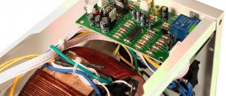
Repair of electromechanical stabilizer ASN-10000/1-EM
Severe contamination of the contacting turns of the autotransformer Thus, the acceleration of contamination becomes avalanche-like, which leads to rapid wear of the autotransformer contacts and burnout of the contact brush, after which the stabilizer will stop producing voltage. The heart of the device is a step-up autotransformer.
Thus, there is a possibility of failure of the engine control output stage. Its design contains a servo drive, which starts and turns off the windings in the device. Why did his head suddenly blow off…….
Repair of Resanta stabilizers can be carried out both at home and in a specialized workshop. Try to repair the damaged one. In addition to these transistors, resistors R45 and R46, included in their collector circuit, burn out due to overheating. In electrical networks where there are frequent power surges, the electric motor may break down within a year of using the equipment. What is a control circuit, its difference from the emergency and thermal circuits, and why the repair of any serious automation must begin with checking the control circuit - it is described in detail, I highly recommend it if you have read this far. The second is the absence of a cooling fan, in this case the cooling is natural.
We carry out this manipulation for both contacts - upper and lower. It is necessary to supply a current of 5 V to the motor outputs. This occurs by opening the contacts of the KL relay, see Voltage stabilizer. Resanta, user review.
DIY voltage stabilizer
To collect all the necessary elements, you will have to go to the store, but you can try to make some parts yourself.
Manufacturing of transformers
This primarily applies to devices T1 and T2. To produce T1, the power of which should be 3 kW, a magnetic core with a cross-section of 1.87 cm2 is required, as well as three PEV-2 conductors. The diameter of the “first of the last” should be 0.12 mm (section - 0.064 mm2). It is used to create the primary winding, the number of turns is 8669. The rest are used for other windings, the diameter of both wires is 0.185 mm. The number of turns is also the same - 552 each.
An alternative is to use a pair of ready-made transformers - TPK-2-2×12V, they are connected in series:
Transformer T2 must have a power of 6 kW. For its manufacture, a toroidal magnetic circuit is used. For the winding they take the same PEV-2, the number of turns in this case is 455. 7 taps are made here. For the first three you need a wire with a diameter of 3 mm. The remaining 4 require tires with a cross section of 18 mm2. The goal is to prevent the transformer from heating up. Bends are made at 203, 232, 266, 305, 348 and 398, counting from below. The current from the network must pass through the tap at the 266th turn.
What else will you need to buy?
All other items must be purchased in the store. The set includes:
- triac optocouplers MOC3041 - 7 parts;
- triacs BTA41-800B - also seven;
- 2 diodes DF005M (VD1 and VD2) and comparator LM339N (for DA2, DA3);
- stabilizer KR1158EN6A (DA1), fuse switch;
- capacitors: 4 oxide (for C1-3, C-5), the same number of film or ceramic (C4, C6-C8);
- resistors with different tolerance percentages: 7 pieces C2-23 for R16-22 with 1%, 30 any with 5%;
- 3 wirewound resistors for R13-14, R25 - SP5-2 or SP5-3;
- 7 current limiting resistors (16 mA) - for R41-47.
The KR1158EN6A stabilizer is mounted on a heat sink. An aluminum plate is used for this purpose. Its area is more than 15 cm2. Triacs are installed on it. All elements can be mounted on one heat sink, but it must have a fairly large cooling surface. Its area is at least 0.16 m2.
You will also need to purchase a KR1554LP5 microcircuit; it will “perform the duties” of a microcontroller. You need to purchase 9 flashing LEDs, but you can also buy regular ones that produce bright red light: for example, AL307KM or L1543SRC-E. There are usually no difficulties with purchasing parts, and spending on them can be considered a reasonable investment that will soon pay off.
Hum and clicks
If the voltage regulator is humming a lot, you need to check that the supply voltage is not above or below the permissible ranges. The adjustment range in most cases lies within 100-250 Volts.
Attention! Even when in good condition, the autotransformer hums evenly and not too loudly. The servo drive also makes a hum when moving the brush assembly.
Relay voltage stabilizers make clicking noises during operation. This is normal, the relays (black rectangles in the picture below) switch taps from the windings to regulate the output voltage.
If the device makes a loud noise, this may indicate sparking of the brush in servo-driven models, problems with the relay, and poor contact of the internal wiring of the device.
Modernization proposals
If the voltage fluctuates approximately in one narrow range, and the transformer track is burned out in this area (as in the last photo), I suggest changing the circuit so that the brush “travels” over another area. To do this, you need to resolder the wire from the lower end of the winding (N) several turns higher (see diagram). Of course, on both parts of the autotransformer. As a result, the brush will slide along another, relatively clean part of the path. The disadvantage of this solution is the narrowing of the adjustment range.
Another solution to this problem is to buy new transformers, which is not economically feasible - after three years of operation it is better to buy a new stabilizer.
Another improvement is to install 12 V coolers (fans) on each transformer, which would blow on the brushes. Ideally, 6 fans. They will literally blow away specks of dust. This will significantly extend the life of the stabilizer.
How do you repair such stabilizers? I look forward to constructive criticism and exchange of experience in the comments.
Servo drive of the device
In ultra-sensitive electromechanical stabilizers, the servo drive responsible for moving the contact brush most often fails. There are two types of solutions to this problem:
- Installation of a new electric motor.
- Repair of damaged elements.
The cost of servos for Resanta stabilizers is extremely high, so a complete replacement of the motor is resorted to only in case of serious damage, when it is impossible to repair it.
Do-it-yourself voltage stabilizer repair is carried out according to the following algorithm:
- The stabilizer housing is opened and the motor with the servo drive is turned off.
- The motor is connected to a power source with the required power.
- An electric current (5 W and not less than 90 mA) is supplied to the motor output.
The operation of the servo drive should be restored, after which the motor is installed in place.
https://youtube.com/watch?v=9AKAPf-V95s
If there is mechanical damage, it is necessary to open the failed motor and replace the burnt out drive elements. Such breakdowns are often observed when the servo drive is overvolted, when stabilizers are used in an electrical network with unstable voltage levels.
Problems with the engine may occur due to the failure of the electronic board through which electricity is supplied to the motor from bipolar transistors. Failed transistors should be replaced in pairs, since a bipolar power supply circuit is used. 10-ohm resistors can also burn out in the circuit, which can be replaced with similar ones or those with a power of 3-5 W more. In the latter case, the reliability of the servo drive increases and problems in equipment operation under peak loads are solved.
Photo and diagram of new boards for electromechanical Resanta
Question from a reader.
I wanted to ask you in which direction should I dig, what should I check. I have a Resanta 15 kW 3 phase stabilizer.
When turned on, it drives two autotransformers to their extreme positions due to high voltage and only one works normally; when we rearranged the control boards, I found out that the problem is in them. I checked all the autotransformers with the working board. What can this behavior give on a board? Are these boards repairable?
Photo and question from here.
Basic faults
From the principle of operation of the electromechanical stabilizer described above, it becomes clear that when the current in the electrical network changes, the motor armature rotates simultaneously and the graphite brush moves.
The constant movement of the servo drive is the main weakness of the electromechanical device. Why? Because as a result of friction of the brush against the coil turns, excessive heating occurs both of the brush and the turns under it.
In addition, friction causes wear on the brush and contamination of the copper wires. The last reason causes sparks to appear.
Considering the fact that in our power lines the current changes very often, the servo drive moves with the same frequency. Such frequent rotation causes failure of the engine itself.
A notable feature is that engine failure causes failure of other parts. Thus, there is a possibility of failure of the engine control output stage.
Experts assemble this cascade based on a pair of transistors Q2 TIP41C and Q1 TIP42C. When these transistors burn out, resistors R45 and R46 also burn out.
They are components of the collector circuit of the above transistors. R45 and R46 are characterized by a resistance of 10 ohms and a power of 2 watts.
When there are such malfunctions, it is necessary to check the linear stabilizer. Its Latvian specialists assemble it on the basis of a zener diode DM4 and a transistor Q3 TIP41C.
If all these components of the electrical circuit of an electromechanical type voltage stabilizer, manufactured by, are burned out, then in any case they need to be purchased and replaced.
General recommendations
Radio-electronic components are found not only in inverter stabilizers, they can be used in control and measuring circuits or display and self-diagnostic devices. This mainly concerns passive elements and microcircuits with a low degree of integration: operational amplifiers, logic elements, combined transistors, current and voltage stabilizers.
The failure of these elements can most often be determined purely by external signs: burnt transistors and diodes have a cracked case, resistors have traces of scorched varnish, capacitors simply swell. Therefore, a close external inspection of the printed circuit board is the first step in identifying a fault.
If the causes of the breakdown cannot be determined visually, a sequence of control measurements must be carried out. First, the conductivity and quality of the dielectric insulation of the circuit in the off state is checked. After this, when power is applied, voltages are measured at key points: at the connection terminals, after the fuse, on filters and stabilizers, transformer windings, and the main components of the control circuit. If the described diagnostic methods do not produce results, it is better to contact a service center, because even a simple breakdown can be very specific, despite the fact that amateur knowledge of electrical engineering and home conditions are not enough to fix it.
Sources
- https://www.rmnt.ru/story/electrical/remont-stabilizatorov-naprjazhenija-svoimi-rukami.1512624/
- https://obrabotkametalla.info/svarit/remont-resanta-sai-190-svoimi-rukami
- https://electricadom.com/remont-stabilizatorov-resanta-tonkosti-i-rekomendacii.html
- https://generatorexperts.ru/elektrogeneratory/remontiruem-resanta.html
- https://SamElectric.ru/powersupply/ustrojstvo-i-remont-elektromehanicheskogo-stabilizatora.html
- https://rusenergetics.ru/remont/remont-rele-stabilizatorov
- https://samelectrik.ru/kakie-byvayut-neispravnosti-stabilizatorov-napryazheniya.html
- https://VoltMarket.ua/neispravnosti-stabilizatora-napryazheniya
- https://amperof.ru/remont/stabilizatorov-napryazheniya.html
[collapse]
Principle of operation
Like all voltage stabilizers, the Resanta brand normalizers consist of:
- automatic transformer.
- electronic unit.
- voltmeter.
- element that connects/disconnects certain windings.
Considering that the manufacturer produces various types of stabilizers, the elements for connecting the windings are different. We will mention them below, namely when we consider the features of the operation and repair of each type of normalizer from the Latvian manufacturer.
The electronic unit of any stabilizer controls the entire operation of the device. It controls the operation of the voltmeter and receives data on the input voltage level. Then he compares this voltage with the normalized one and determines how many volts need to be added or subtracted.
After this, it is determined which stabilizer windings need to be connected or disconnected. When this information is known, the electronic unit connects/disconnects the necessary windings using a relay or servo drive and our electrical appliances receive a normalized current.
This principle of current stabilization is inherent in every voltage stabilizer from. However, the stabilization process differs in different models of the company. They are due to the fact that the transformer windings are connected/disconnected differently.
The company produces two types of stabilizers:
- Electromechanical.
- Relay.
And, of course, the repair of each of them has its own characteristics.
Causes of breakdowns
The main cause of malfunction of the Resanta 10000W voltage stabilizer is improper operation of the equipment.
Quite often, overheating of rectifiers is observed when using equipment in a dusty room. Dirt settles inside the case, which impairs the cooling of the device, and problems arise with overvoltage of the power part and execution boards. Also, the cause of breakdown of electrical rectifiers can be operation in conditions of high humidity. The contacts and boards begin to oxidize, the connection deteriorates, which ultimately leads to serious damage to the stabilizers - they can be restored by replacing the servo drive or power elements.
In the stabilizer operating instructions you can find all the recommendations for using the equipment, which will help prevent the occurrence of typical breakdowns and the need for expensive and complex equipment repairs.
In the Resanta line you can find both simple and inexpensive household models that are intended for indoor use, as well as specialized industrial installations that can be used in conditions of high humidity and dusty, contaminated workshops. By choosing the right stabilizer, you can guarantee trouble-free operation and no breakdowns even under increased load.
Servo motor repair
When the engine itself burns out, there are two options:
- Buying a new one and installing it.
- An attempt to restore an old engine.
The second option makes it possible to revive the engine on your own, however, not for a long time. For resuscitation, you need to disconnect the engine from the general circuit. After this, it must be connected to a powerful power source.
Your task is to supply current to its outputs with a constant voltage of 5 volts. The current should be between 90 and 160 mA. When such a current is supplied, every small particle of “garbage” burns out on the motor brushes.
Helpful advice: since the motor is of a reversible type, the polarity must be changed when applying voltage. This procedure is carried out twice.
After such actions, the engine will be able to work again, and the stabilizer will perform its main function. Next, according to a simple diagram, you can carry out the procedure for connecting the voltage stabilizer released.
This circuit involves connecting the input phase and neutral cables to the input phase and neutral terminals, respectively. The connection of the output wires is similar. A grounding wire must also be connected.
Connection errors
1
You may have everything connected perfectly and the diagram followed, but the stabilizer will constantly heat up and turn off, or errors will appear on its display.
Read in detail about where you can and where you should never place this device in the article “Where to install a voltage stabilizer in the house.”
2
Of course, this point can hardly be called a mistake. Moreover, 90% of consumers do just that.
However, this switch can really save your device from failure.
First you turn off the machines on the stabilizer panel.
Then move the switch itself to the TRANSIT or BYPASS position.
And only then turn on the machines again.
Many people forget about this and switch under load. Which ultimately leads to breakdowns.
With a 3-position automatic machine this is impossible. You automatically switch the voltage, without any manipulation on the stabilizer. And all this with one key!
There is no need to remember any sequence. So this procedure can be safely trusted to any family member.
3
You can choose a smaller cross-section only when powering individual electrical receivers.
If your whole house is sitting on a stabilizer, then please follow the input parameters according to the entire general house load.
4
For some reason, many people forget that often the entire load of your home passes through the stabilizer. Exactly the same as on the automatic input.
At the same time, in the electrical panel all the wires are crimped, even on light switches with minimal currents, but on the terminal blocks of the stabilizer or its circuit breakers, you can always find a bare wire simply pressed in with a screw.
Therefore, do not skimp and purchase the appropriate tips along with the device in advance.
5
Sometimes after connecting the stabilizer, the input machine starts to knock out. In this case, without a stabilizer, everything is fine and nothing is turned off.
Many people immediately blame it on an incorrect connection diagram or a defect in the device. They take it for warranty repairs, etc.
But the reason may be completely different. If your voltage is too low, 150-160V, then when you increase it to the standard 220-230V, the current in the network will increase significantly.
Hence all the problems
Please pay attention to this before you take it back to the store.
Sources - https://cable.ru, Kabel.RF