The operation of an electric drive is characterized primarily by the mechanical characteristics of the engine? = f (M) or n = f (M). Electromechanical characteristics are also often used for a DC motor? = f (Iа) or n = f (Iа), where ?, n, Iа, M are, respectively, angular velocity, rotational speed, armature current and motor torque. Mechanical characteristics can be calculated in both absolute and relative units. For DC motors, the most widespread calculation of characteristics is in relative units.
When calculating in relative units, the nominal data of the engine Iа, Mnom, Unom, nnom are taken as the basic values. Sometimes values that differ from the nominal ones (for example, static load moment) are taken as base values. Values expressed in relative units will be further indicated by a sign.
The resistance of the main circuit in relative units is determined in fractions of the nominal resistance. By nominal is meant the resistance of the armature circuit, which, with a stationary armature and rated design voltage Un, determines the rated current strength in the armature:
The armature circuit resistance consists of internal and external resistances. The values of the internal resistance of the motor windings of the DP and D series in fractions of the nominal at PV = 25% are given in table. 2.23. Column rя* indicates the resistance of the armature and additional poles of the motors, and column r'n* indicates the resistance of the winding of series-excited motors. The resistance of the stabilizing windings of parallel excitation motors is so small that it can be neglected. When calculating typical characteristics for a group of motors, the winding resistance should be determined as the arithmetic mean of the values given in the corresponding rows of the table. 2.23.
The calculation of the mechanical characteristics of engines in relative units is given below and is universal. This calculation method is suitable for various methods of excitation and connection of windings.
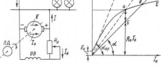
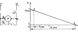
The engine switching diagram is shown in Fig. 2.12, which shows three options (1, 2, 3) for switching on series excitation windings. The current strength in these windings is indicated by Ip1, Ip2, Ip3. The parallel excitation winding generally receives power from an independent source with voltage Uв.
When calculating the mechanical characteristics, as a rule, they use the well-known switching circuit of the serial excitation winding, the resistance of the series and shunt circuits Rп and Rш, the voltage of the armature circuit (main circuit) power supply Uг, the MMF of the parallel excitation winding and the ratio between the MMF of the serial and parallel excitation windings at rated load. The voltage Ug can have a load-independent value Ug - const (DC network). When using rotating or static energy converters, set the external characteristic of these converters Ug = f (I) (I is the load current).
The MMF of the main poles of the motor is determined by the total effect of the electric current in the field windings located on these poles. Since the nominal MMF, taken as the basic one, is the sum of the MMF of the parallel excitation winding and the MMF of the series excitation winding or stabilizing winding, it can be assumed that the MMF of the parallel excitation winding in relative units will be 0.5 for motors of the DP and D series of mixed excitation and 0 ,9 for motors of the DP and D series of parallel excitation. The series excitation winding or stabilizing winding will account for the rest of the MMF. Considering that this part corresponds to the MMF when the rated current flows, for any current strength the MMF of the series excitation winding can be expressed by the following formulas:
for motors of the DP and D series of mixed excitation,
where I*п is the current strength flowing through the series excitation winding;
for parallel-excitation motors with stabilizing winding of the DP and D series
The total MMF of the main poles is expressed as an algebraic sum of the MMF of series and parallel excitation windings:
In some cases, to implement increased (lower) rotation speeds of MDS motors, the parallel excitation windings are taken less (more) than the nominal one.
The general method for calculating the mechanical characteristics of DC motors in the considered switching circuit (see Fig. 2.12) is to find the dependencies F* = f (Iа*) and Iп* = f (Iа*) and then proceed to the dependence n* = f ( M*).
The dependence of the current in the series winding on the motor armature current is established using one of the following equations:
each of which is valid in the presence of a series excitation winding in only one circuit.
Accordingly, the dependence of the EMF on the armature current strength is determined by one of the following dependencies:
The rotation frequency n at a given armature current is found by the formula n = E/FsE, where F is the magnetic flux of the motor; cE is the voltage proportionality coefficient.
To obtain equations in relative units, we introduce the following basic quantities: nb = nnom; Ib = Inom; Eb = Unom; Fb = Fnom; Rb = Rnom. Using relations
we can write nnom/no = c'E, in which
where rdv = rya + rp; n0 is the rotation speed at ideal idle.
Then we write the formula for determining the rotation speed in relative units as follows:
since in relative units Ф* = (E/n)*.
Magnetic flux F* for the corresponding armature current with a known MMF of the main poles (F* = F*pair + F*p) is determined from the universal load characteristics. The load characteristic is the dependence (E/n)* = f (F*) at a constant armature current I*i. Since the type of load characteristics depends on the strength of the armature current, they are depicted in the form of a family of curves plotted at different values of Iа. The characteristic at Iа = 0 is the magnetization curve of the motor.
In Fig. 2.13 shows the universal characteristics of engines of the DP and D series. The characteristics are shown in relative units. The basic values are taken as the nominal MMF of the main poles of the motor at PV = 25% and the rated magnetic flux F of the main poles when a current of rated strength flows through the motor armature at PV = 25% in the direction corresponding to the motor mode. Typical load characteristics correspond to the actual load characteristics of specific engines of the DP and D series, differing from the characteristics obtained based on experience by 2-3%.
Electromagnetic torque of the motor (in N?m)
where cM is the torque coefficient.
The torque on the motor shaft differs from the electromagnetic moment by an amount determined by mechanical losses and losses in the armature iron. Thus, the torque on the motor shaft can be represented as follows:
where ?P is power loss due to friction; ?Рст — power loss in steel; kM—moment proportionality coefficient.
The parameter ?M* = kM* (?P* + ?P*st)/n* is determined from curves expressing the dependence ?M* = f (E/n)* at various constant values of rotation speed n*. Such curves, plotted in relative units, are shown in Fig. 2.14.
Using these curves, it is not difficult to find the torque ?M* at different magnetic fluxes of the main poles and rotation frequencies. The torque coefficient cM can be determined based on the fact that at basic current strength, magnetic flux and rotational speed, the torque on the motor shaft must also be equal to the basic (nominal) one. Therefore, using expression (2.39), we can write that when Mdv = Mb = Mnom i.e.
Having determined from Fig. 2.14, that for (E/n)* = 1 and n* = 1?M* = 0.03, we find
Finally, the formula for determining the torque on the shaft has the form
Basic calculation indicators
How to find out the power of an electric motor will be shown later in the article, using an example with initial data.
A good science project doesn't stop at building a power apparatus. It is very important to calculate the electric motor power and various electrical and mechanical parameters of your device and calculate the electric motor power formula using unknown values and useful formulas.
To calculate the electric motor, we will use the International System of Units (SI). This is the modern metric system, officially adopted in electrical engineering.
One of the most important laws of physics is Ohm's fundamental law. He states that the current through a conductor is directly proportional to the applied voltage and is expressed as:
I=V/R
where I is current, in amperes (A);
V is the applied voltage, in volts (V);
R - resistance, in ohms (Ω).
This formula can be used in many cases. You can calculate the resistance of your motor by measuring the current drawn and the applied voltage. For any given resistance (in motors this is mostly coil resistance), this formula explains that the current can be controlled by the applied voltage.
The consumed electrical power of the engine is determined by the following formula:
Pin = I * V
where Pin is the input power, measured in watts (W);
I is the current measured in amperes (A);
V is the applied voltage, measured in volts (V).
Calculation of current by power - formula, online calculation, selection of machine
What should you do if you bought or somehow obtained an electric motor that does not have a tag or nameplate indicating its power, rotation speed, etc.?
Or on the old engine this data was erased and became unreadable.
In this case, you do not have a passport or any other technical documentation at hand. Is it possible to find out the engine parameters yourself in this case?
Of course yes, in several ways. Let's look at the most popular of them.
Initially, to accurately determine the power, you will need to find out the synchronous speed of the shaft, and before that, find out where we have the beginning of each winding and where is its end.
According to GOST 26772-85, the windings of three-phase asynchronous motors must be marked with the letters:
Even earlier, one could find the inscriptions N1-K1 (beginning-end of winding No. 1), N2-K2, N3-K3.
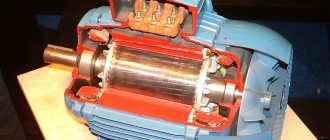
On some engines, to make it easier to recognize the ends of the windings, they are brought out from different holes on one side or the other. Like in the photo below.
But you cannot always trust such conclusions. Therefore, it never hurts to check everything manually.
If there are no marks or letters on the barno, and you don’t know where your winding starts and where it ends, read the instructions under the spoiler.
Take a multimeter as an assistant and set it to resistance measurement mode.
With one probe, touch any of the six terminals, and with the other, alternately touch the remaining five wires, thereby looking for the corresponding pair.
When it is located on the multimeter display, a number should appear showing a certain resistance in Ohms.
Expert opinion
It-Technology, Electrical power and electronics specialist
Ask questions to the “Specialist for modernization of energy generation systems”
How to calculate power knowing current and voltage? A linear motor is essentially an induction motor whose rotor is turned so that instead of producing a rotational force by a rotating electromagnetic field, it produces a linear force along its length by installing a bias electromagnetic field. Ask, I'm in touch!
Asynchronous electrical machines
Squirrel-cage motors
Their rotor winding is a set of metal rods that connect two rings. The resulting figure is called a “squirrel wheel”. At the moment voltage is applied to the stator winding, a short circuit current arises in the rotor, the energy of which is spent on unwinding the shaft and is thereby extinguished. It has a slightly lower efficiency than synchronous machines, it does not exceed 80%.
Wound rotor motors
The start-up of high-power squirrel-cage asynchronous motors (more than 30 kW) is associated with extreme overload of the supply network. To eliminate this phenomenon, machines with a wound rotor are used, the winding of which consists of three coils connected by a star. Their ends are connected by carbon brushes to three slip rings located on the motor axis.
By changing the rotor resistance, you can change the rotation speed. The advantage of a machine of this type is the absence of overload at the time of start-up and a smooth increase in torque. Therefore, it is used in lifting equipment. The disadvantage is the complexity of the device and lower efficiency than that of machines with a squirrel-cage rotor, it is no more than 60%.
What kind of lighting do you prefer?
Built-in Chandelier