There are 2 types of single-phase asynchronous motors - bifilar (with a starting winding) and capacitor. Their difference is that in bifilar single-phase motors the starting winding operates only until the motor accelerates. Afterwards it is turned off by a special device - a centrifugal switch or a start-up relay (in refrigerators). This is necessary because after overclocking it reduces efficiency.
In capacitor single-phase motors, the capacitor winding runs all the time. Two windings - the main and auxiliary, they are shifted relative to each other by 90°. Thanks to this, you can change the direction of rotation. The capacitor on such engines is usually attached to the housing and is easy to identify by this feature.
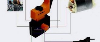
Connection diagram for a single-phase motor via a capacitor
When connecting a single-phase capacitor motor, there are several options for connection diagrams. Without capacitors, the electric motor hums, but does not start.
- 1 circuit - with a capacitor in the power supply circuit of the starting winding - starts well, but during operation the power it produces is far from rated, but much lower.
- 3, the connection circuit with a capacitor in the connection circuit of the working winding gives the opposite effect: not very good performance at start-up, but good performance. Accordingly, the first circuit is used in devices with heavy starting, and with a working capacitor - if good performance characteristics are needed.
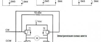
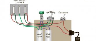
- Diagram 2 - connecting a single-phase motor - install both capacitors. It turns out something between the options described above. This scheme is used most often. She's in the second picture. When organizing this circuit, you also need a PNVS type button, which will connect the capacitor only during the start time, until the motor “accelerates”. Then two windings will remain connected, with the auxiliary winding through a capacitor.
The device of asynchronous engines
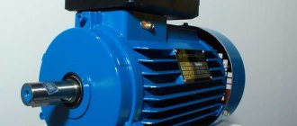
An asynchronous motor, like everything else, has a stator and a rotor. Such a motor can be three or single phase. Below we will look at a single-phase machine, so this article is about it.
Asynchronous motors are characterized by a low noise level, so they are installed in those devices whose quiet operation is very important. An example could be a refrigerator, air conditioner, split system.
Single-phase motors can be divided into two more subtypes: bifilar (those with a starting winding) and capacitor. Their main difference (we have already discussed this) is the duration of operation of the auxiliary windings. In the first case, the winding is turned off immediately after the engine accelerates. This happens using a special centrifugal switch. It is important to turn off the starting winding because it reduces the efficiency of the machine after starting and can even lead to its breakdown.
Capacitor motors are characterized by the fact that the starting winding in them works even after the motor starts running. Both of them are located perpendicular to each other. This allows you to change the direction of rotation of the rotor. The capacitor itself is usually attached to the drive housing, which makes it easy to identify.
A bifilar or capacitor drive can be more accurately determined by measuring the resistance of the windings. If the indicator in the auxiliary winding is at least two times less than in the working winding, this most likely indicates that the machine is bifilar, and also that this winding is a starting winding. From this conclusion it is clear that there must be a centrifugal switch or a starting relay.
In the second type of single-phase drives, two windings are always in operation, which means they are turned on using a button, toggle switch or machine.
If the motor was started successfully, but the shaft began to rotate in the wrong direction, the direction of its rotation can be changed. To do this, you need to change the starting windings. This can be done using a two-position switch. You need to connect a capacitor terminal to its central contact, and to the other two terminals from phase and “zero”.
Connection diagram for a three-phase motor via a capacitor
Here, the voltage of 220 volts is distributed into 2 series-connected windings, where each is designed for this voltage. Therefore, the power is lost almost twice, but such an engine can be used in many low-power devices.
The maximum power of a 380 V motor in a 220 V network can be achieved using a delta connection. In addition to minimal power losses, the engine speed also remains unchanged. Here, each winding is used for its own operating voltage, hence the power.
It is important to remember: three-phase electric motors have higher efficiency than single-phase 220 V motors . Therefore, if there is a 380 V input, be sure to connect to it - this will ensure more stable and economical operation of the devices. To start the motor, you will not need various starters and windings, because a rotating magnetic field appears in the stator immediately after connecting to a 380 V network.
Useful: Wiring diagram for a chandelier with 5 lamps and its repair
How does it work
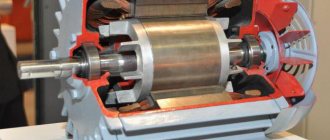
A single-phase 220V motor with a capacitor can have a power from 5 W to 10 kW. It all depends on the design features of the machine. The rotor of such a drive, as a rule, is a short-circuited winding of the “squirrel cage” type. These are aluminum rods cast into grooves and short-circuited.
There are two windings in such a drive, despite its name. They are always offset by 90° relative to each other. In this case, the so-called main winding takes up more space in the stator.
A single-phase motor received this name due to the fact that only one, main (or working) winding works with the motor. An alternating current flows through it, creating a magnetic field that changes from time to time. We can say that it consists of two fields that rotate towards each other, and their amplitude is the same.
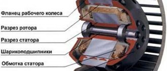
Schematic arrangement of windings
The law of electromagnetic induction states that magnetic fluxes in closed rotor turns cause the appearance of an induced current. The latter, in turn, interacts with the field that generates it. If all moments of forces that act on the rotor are equal to zero, the part does not move.
And with the beginning of rotation, the described equality will be immediately violated. This is due to the sliding of the rotor turns. It will be different relative to the rotating magnetic field. Consequently, the Ampere force that acts on closed rotor turns from the side of the direct magnetic field will become greater than from the side of the reverse magnetic field.
The occurrence of an induced current in closed rotor turns is possible only when the turns intersect the field lines. For this to happen, the speed of rotation of the turns must be slightly less than that at which the field rotates.
This was the source of the name for electric drives of this type. They were called asynchronous.
Mechanical load is inversely proportional to rotation speed. This means that if the load increases, the rotation speed decreases. The magnitude of the induction current in the rotor turns increases. This results in an increase in the mechanical power of the drive, as well as the alternating current power it consumes.
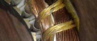
Winding appearance
Let's sum up a short summary:
- Electric current is the cause of a pulsating magnetic field in the motor stator. It can be considered as two separate fields that rotate towards each other with equal amplitude.
- If the rotor does not move, both fields cause moments that are equal to zero, but in different directions.
- When the rotor begins to rotate in one direction, one of the moments will prevail over the other, that is, the engine will rotate only in a given direction.
- In the absence of special starting mechanisms in the engine, during start the corresponding torque will be zero, that is, the drive will not begin to rotate.
Online calculation of motor capacitor capacity
| Enter data for calculating capacitors - motor power and efficiency |
There is a special formula that can be used to calculate the required capacity accurately, but you can easily get by with an online calculator or recommendations that are derived from many experiments:
The working capacitor is taken at the rate of 0.8 μF per 0.1 kW of engine power; The launcher is selected 2-3 times more.
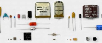
Capacitors must be non-polar, that is, not electrolytic. The operating voltage of these capacitors must be at least 1.5 times higher than the network voltage, that is, for a 220 V network we take capacitors with an operating voltage of 350 V and higher. To make starting easier, look for a special capacitor in the starting circuit. They have the words Start or Starting in their markings.
Starting capacitors for motors
These capacitors can be selected using the method from smallest to largest. Having thus selected the average capacity, you can gradually add and monitor the operating mode of the engine so that it does not overheat and has enough power on the shaft. Also, the starting capacitor is selected by adding until it starts smoothly without delays.
During normal operation of three-phase asynchronous electric motors with capacitor start, connected to a single-phase network, it is assumed that the capacitance of the capacitor will change (decrease) with increasing shaft speed. At the moment of starting asynchronous motors (especially with a load on the shaft) in a 220 V network, an increased capacity of the phase-shifting capacitor is required.
How it starts
- In fact, the motor is driven by a magnetic field. It begins to rotate the rotor - the moving element of the motor. It is created using two windings: working and starting. The launcher (auxiliary) is smaller in size. It is connected to the electrical network through inductance or capacitance. It turns on only at startup. Low-power motors have a short-circuited starting winding.
- Starting is done by pressing the start button. It is held for several seconds while the rotor accelerates.
- When the start button is released, the starting winding stops working, that is, the engine switches to two-phase operation. It is supported by a corresponding component of the alternating magnetic field.
- The starting winding operates for a fairly short amount of time. Usually no more than three seconds. If you increase the operating time of the auxiliary winding, the motor will overheat, causing an insulation fire or damage to the entire motor. Pressing the start button in a timely manner is a very important point when working with a single-phase motor.
- Electric motors usually have a centrifugal switch or thermal relay. This increases the reliability of the machine body.
- A centrifugal switch is needed to disconnect the auxiliary winding while the rotor is picking up speed. The user does not interfere with this, since the process is completely automated.
- A thermal relay is needed to turn off both windings if they overheat.
Reversing single-phase synchronous machines
To start, these motors require a second winding on the stator, which includes a phase-shifting element, usually a paper capacitor. It is possible to reverse only those in which both stator windings are equivalent - in terms of wire diameter, number of turns, and also provided that one of them does not turn off after a set of revolutions.
The essence of the reversing circuit is that the phase-shifting capacitor will be connected to one of the windings, then to the other. For example, consider an AIR 80S2 asynchronous single-phase motor with a power of 2.2 kW.
There are six threaded terminals in its terminal box, designated by the letters W2 and W1, U1 and U2, V1 and V2. To ensure that the motor rotates clockwise, the commutation is performed as follows:
- Mains voltage is supplied to terminals W2 and V1.
- The ends of one winding are connected to terminals U1 and U2. To power it, they are connected by jumpers according to the scheme U1–W2 and U2–V1.
- The ends of the second winding are connected to terminals W2 and V2.
- The phase shifting capacitor is connected to terminals V1 and V2.
- Terminal W1 remains free.
To rotate counterclockwise, change the position of the jumpers; they are placed according to the scheme W2–U2 and U1–W1. The automatic reverse circuit is also built on two magnetic starters and three buttons - two normally open “Start” and one normally closed “Stop”.
conclusions
As you can see, reversing a single-phase motor is not something complicated - on the contrary, it is widely used in many systems and mechanisms as part of the operation of the engine. However, in cases where reverse rotation is not provided, you have to look for an alternative way to reverse the rotation. Depending on the design of the motor, this can be done without disassembling the entire mechanism. It is only important to carry out the work with great attention to detail and with knowledge of the matter, to draw a diagram so that problems and emergency situations do not arise in the future.
Reverse commutator motors
The connection circuit of its windings is similar to that used in DC motors with series excitation. One collector brush is connected to the stator winding, and the supply voltage is supplied to the other brush and the second terminal of the stator winding.
When the position of the plug in the socket changes, the rotor and stator magnets simultaneously reverse polarity. Therefore, the direction of rotation does not change. Just as this happens in a DC motor with a simultaneous change in the polarity of the supply voltage on the field and armature windings. It is necessary to change the order of phase - zero only in one element of the electrical machine - the collector, which provides not only spatial, but electrical separation of the conductors - the armature windings are isolated from each other. In practice this is done in two ways:
- Physical change in the installation location of the brushes. This is irrational, since it is associated with the need to make changes to the design of the device. In addition, it leads to premature failure of the brushes, since the shape of the groove at their working end does not coincide with the shape of the commutator surface.
- By changing the position of the jumper between the brush assembly and the excitation winding in the terminal box, as well as the connection point of the power cable. Can be implemented using one multi-position switch or two magnetic starters.
Do not forget that all work on rearranging jumpers in the terminal box or connecting the reversing circuit must be carried out with the voltage completely removed.
Source: electriktop.ru
Changing the direction of drive movement
In fact, the starting winding in the motor is needed in order to make the rotor move, because it can only start rotating with outside help. Otherwise it won't start.
Both windings, working and starting, are located on the stator, as already mentioned, perpendicular to each other. But the working phase takes up twice as much space as the starting phase. The rotor in such an engine has the simplest design. As a rule, this is a “squirrel cage”.
What would happen if there was no auxiliary winding on the stator of a single-phase 220V motor? What if you don't supply current there? In this case, when the drive is connected to the network, a magnetic field will appear in the main winding and it will pulsate. At the same time, the rotor begins to penetrate a changing magnetic flux. But if the rotor was not in motion from the very beginning, and the alternating current supply will only go to the main winding, then the part will not work. This is because the rotational moment clockwise and counterclockwise will be zero, that is, there will be no reason for the rotation to start. Even though an EMF will be induced in the rotor.
But if you push the rotor and the shaft a little, it will continue to rotate in the direction specified by the starting push. There will be two reasons for this:
- the occurrence of EMF and corresponding currents in the rotor, which are repelled by the magnetic field according to Ampere’s law;
- the magnitude of the resulting moment in the direction of the push will be greater than against its direction.
As a result, the rotor will continue to rotate.
To get a reverse of a single-phase 220V motor with a capacity, you just need to take care of giving a starting impulse in the opposite direction from the original direction. This can be achieved by changing the relative order in which the phases alternate in the operating and starting windings.
To ensure such conditions, it will be necessary to switch one of the two windings. In other words, the “polarity” of connecting the winding terminals to the network and the capacitor must be changed. The implementation is quite simple, because on single-phase motors there are always terminal blocks where all the ends of the windings are output. The main winding is characterized by a small resistance relative to the starting winding, so it is very easy to detect them with a multimeter in ohmmeter mode.
It is best to bring the ends of the auxiliary winding to a switch with two poles without latching.
Reverse circuit - implementation in practice
In order for the rotor to start rotating in the opposite direction, it is necessary to swap the second and third phases. Note that at first it will continue to move in the original direction by inertia, and only after some time it will enter a state of equilibrium, from which it will change direction.
The polarity of the starting winding, necessary to set the direction, can be done according to the circuit using a special control toggle switch. First of all, it must be selected based on the permitted motor voltage and current load, as well as the required fixed positions - 2 or 3. The current to the toggle switch should be drawn from the starting winding, since it does not work for so long and generally saves resources. This way you can reduce the cost of maintaining the entire system and the contact group in particular.
Experts advise reversing an asynchronous motor as follows:
- if the start-up is expected to be difficult, then it can be simplified with the help of an additional capacitor. This is only relevant for schemes that use a self-resetting NVD connection. Then the reverse toggle switch will turn on only if the rotor is braked, but not during operation, increasing the efficiency and stability of the system;
- The seat of the toggle switch for reverse must be protected from accidental operation. Since this is accompanied by huge current surges, this will save energy and engine life;
- if the mechanism does not reverse as required, then after connecting you need to check that the wires are connected correctly - often the terminals are confused and the whole circuit gets confused. Also, performance depends on the integrity of the wiring.
Given the fact that even the smallest problems can lead to reverse failure, it is important to thoroughly check the entire mechanism before starting it up. This will allow you to avoid breakdowns and emergency situations.
Reversing three-phase asynchronous machines
The direction of movement of the rotating magnetic field of asynchronous electric motors depends on the order of the phases, regardless of whether its stator windings are connected by a star or a triangle. For example, if phases A, B, C are applied to input terminals 1, 2 and 3, respectively, then the rotation will go (supposedly) clockwise, and if to terminals 2, 1, and 3, then counterclockwise. The connection diagram via a magnetic starter will save you from the need to unscrew the nuts in the terminal box and physically rearrange the wires.
Three-phase asynchronous machines at 380 volts are usually connected with a magnetic starter, in which three contacts are located on the same frame and close simultaneously, subject to the action of the so-called retractor coil - a magnetic solenoid operating on both 380 and 220 volts. This saves the operator from close contact with live parts, which can be unsafe at currents above 20 amperes.
For reverse starting, a pair of starters is used. The supply voltage terminals at the input are connected in a direct manner: 1–1, 2–2, 3–3. And at the exit counter: 4–5, 5–4, 6–6. To avoid a short circuit when accidentally pressing two “Start” buttons on the control panel simultaneously, voltage is supplied to the retractor coils through additional contacts of opposite starters. So that when the main group of contacts is closed, the line that goes to the solenoid of the adjacent device is open.
The control panel is equipped with a three-button post with single-position – one action per press – buttons: one “Stop” and two “Start”. The wiring in it is as follows:
- one phase wire is fed to the “Stop” button (it is always normally closed) and jumpers from it to the “Start” buttons, which are always normally open.
- From the “Stop” button there are two wires to additional contacts of the starters, which close when they are triggered. This ensures blocking.
- From the “Start” buttons, cross one wire to the additional contacts of the starters, which open when they are triggered.
Read more about connection diagrams for magnetic starters for three-phase electric motors here.
Option 3: changing the starting winding to the working winding, and vice versa
It is possible to organize the reverse of a single-phase 220V motor using the methods described above only if taps from both windings with all beginnings and ends come out of the housing: A, B, C and D. But there are often motors in which the manufacturer intentionally left them outside only 3 contacts. In this way, he protected the device from various “homemade products”. But still there is a way out.
The figure above shows a diagram of such a “problematic” motor. It only has three wires coming out of the housing. They are marked with brown, blue and purple colors. The green and red lines corresponding to the end B of the starting winding and the beginning C of the working winding are interconnected internally. We will not be able to access them without disassembling the engine. Therefore, it is not possible to change the rotor rotation using one of the first two options.
In this case, do this:
- Remove the capacitor from the initial terminal A;
- Connect it to the final terminal D;
- From wires A and D, as well as the phase, taps are made (you can reverse it using a key).
Read also: Spider for lifting loads
Look at the picture above. Now, if you connect the phase to tap D, the rotor rotates in one direction. If the phase wire is transferred to branch A, then the direction of rotation can be changed in the opposite direction. Reversing can be done by manually disconnecting and connecting the wires. Using a key will help make the job easier.
Important! The last version of the reversible connection diagram for an asynchronous single-phase motor is incorrect. It can only be used if the following conditions are met:
- The length of the starting and working windings is the same;
- Their cross-sectional area corresponds to each other;
- These wires are made of the same material.
All these quantities affect resistance. It must be constant at the windings. If suddenly the length or thickness of the wires differ from each other, then after you organize the reverse, it turns out that the resistance of the working winding will become the same as it was before for the starting winding, and vice versa. This may also cause the engine to fail to start.
Attention! Even if the length, thickness and material of the windings are the same, operation with a changed direction of rotation of the rotor should not be prolonged. This can lead to overheating and engine failure. The efficiency also leaves much to be desired.
It is easy to reverse a 220V asynchronous motor if the ends of the windings are diverted from the housing to the outside. It is more difficult to organize it when there are only three conclusions. The third reversing method we considered is suitable only for short-term connection of the motor to the network. If work with reverse rotation promises to be long, then we recommend opening the switching box using the methods described in options 1 and 2: this is safe for the unit and efficiency is maintained.
Option 1: reconnecting the working winding
To change the direction of rotation of the motor, you can only swap the beginning and end of the working (permanently on) winding, as shown in the figure. You might think that to do this you would have to open the case, take out the winding and turn it over. There is no need to do this, because it is enough to work with the contacts from the outside:
- There should be four wires coming out of the housing. 2 of them correspond to the beginnings of the working and starting windings, and 2 to their ends. Determine which pair belongs only to the working winding.
- You will see that two lines are connected to this pair: phase and zero. With the motor turned off, reverse the phase by changing the phase from the initial winding contact to the final one, and zero - from the final to the initial one. Or vice versa.
Read also: Do-it-yourself repair of LED lamps era
As a result, we get a diagram where points C and D change places with each other. Now the rotor of the asynchronous motor will rotate in the other direction.