Classic starters and contactors are gradually becoming a thing of the past. Their place in automotive electronics, household appliances and industrial automation is occupied by solid-state relays - a semiconductor device that does not have any moving parts.
The devices have different designs and connection diagrams, which determine their scope of application. Before using the device, you need to understand its principle of operation, learn about the features of operation and connection of different types of relays. The answers to the above questions are described in detail in the presented article.
Flaws
In addition to the positive qualities of solid-state relays, it is worth highlighting a number of disadvantages:
- When open, the product heats up due to the high resistance in the pn junction circuit. To avoid negative consequences in devices that pass high currents through themselves, it is necessary to provide cooling.
- When closed, the resistance increases and reverse leakage current appears (measured in mA).
- When taking the current-voltage characteristic, its nonlinear nature is noticeable.
- Some types of solid-state relays require strict polarity when connecting output circuits. This applies to those devices that are designed to operate in direct current conditions.
- In the event of a breakdown, there is a high risk of blocking the input contacts. The reason may be a breakdown of the power switch. For comparison, the contacts of classic relays (if they fail) remain open.
- Protection against erroneous operations caused by voltage surges is required. This is due to the high response speed.
- Solid-state relays pass current along the return path with a slight delay, which is due to the use of semiconductor elements in the circuit.
Operating principle of TTP
The operation of a solid state relay is quite simple. Most SSRs are designed to control automation in 20-480 V networks.
Optical isolation allows you to create control signals of minimal power, which is critical for sensors operating from autonomous power sources (+)
In the classic version, the device body includes two contacts of the switched circuit and two control wires. Their number may change as the number of connected phases increases. Depending on the presence of voltage in the control circuit, the main load is switched on or off by semiconductor elements.
A feature of solid-state relays is the presence of non-infinite resistance. If the contacts in electromechanical devices are completely disconnected, then in solid-state devices the absence of current in the circuit is ensured by the properties of semiconductor materials.
Therefore, at elevated voltages, small leakage currents may appear, which can negatively affect the operation of connected equipment.
Tips for choosing
Overload protector
You can buy solid-state relays only in a specialized electronics store. Experienced specialists will help you choose the best device for specific purposes. The cost of the product is influenced by the following factors:
- relay type;
- presence of locking mechanisms;
- body material;
- on time;
- manufacturer and country of production;
- power;
- required energy;
- dimensions.
When purchasing, it is important to take into account that there must be a power reserve that is several times greater than the working one. This will protect the relay from damage
Special fuses are also used additionally. The most reliable include:
- GR – used in a wide range of loads, characterized by high performance.
- GS – operate over the entire current range. Reliably protect the device from excess load of the electrical network.
- AR - protects semiconductor device components from short circuits.
Such devices provide high protection against breakdowns. Their cost is comparable to the price of the relay itself. Fuses of classes B, C, D have lower protective properties and, accordingly, lower cost.
Tools
0 votes
+
Vote for!
—
Vote against!
To ensure contactless communication of various devices without the use of electromagnets, a solid-state relay is used. We will talk about the features, operating principle and connection diagram of this device further.
Table of contents:
- Solid state relay - operating principle
- Advantages and scope of use of solid state relays
- Types of solid state relays
- Selecting and purchasing a solid state relay
- Features of connecting a solid state relay
Solid state relay - operating principle
A solid state relay is a device that provides contact between low-voltage and high-voltage electrical circuits.
Considering the structure of this device, most models are similar to each other, they have minor differences that do not in any way affect the principle of their operation.
The structure of a solid state relay includes the presence of:
- entrance,
- optical isolation,
- trigger circuit
- switch circuits,
- protection circuits.
The input is the primary circuit, which is characterized by the presence of a resistor on a permanent insulator, which has a series connection. The main function of the input circuit is to receive a signal and transmit a command to the solid state relay device, which switches the load.
An optical isolation device is used to isolate the input and output AC network. The type of relay and its operating principle depend on the type of this component.
A trigger circuit design is used to process the input signal and switch the output. It acts as a separate element, and in some models it is part of the optical isolation.
To apply voltage to the load, a switching type circuit is used, which includes a transistor, a silicon diode and a triac.
To protect the SSR from malfunctions or errors, a separate protection circuit is used. This device comes in two types: internal and external.
The solid state relay circuit consists of:
- control systems,
- solid state relay devices,
- motor, pump, welding machine, transformer or heater.
To switch an inductive load using a solid-state relay, the current reserve should be increased by 6-8 times.
The principle of operation of a solid state relay is to close or open contacts that transmit voltage directly to the relay. To activate the contacts, an activator is required. Its role in a solid-state relay is performed by a semiconductor or solid-state device. In devices that operate with alternating current, this is a thyristor or triac, and for devices with direct current, it is a transistor.
A device characterized by the presence of a key transistor is a solid-state relay. This is, for example, a motion or light sensor that transmits voltage using a transistor.
A galvanic isolation effect appears between the voltage in the coil and the power contacts, which disappears due to the presence of an optical circuit.
Advantages and scope of use of solid state relays
Solid state relays often replace conventional contactors due to their many advantages over them. Let's look at the main advantages of a solid-state relay:
1. Low power consumption - due to the lack of electromagnetic diversity, the electromagnetic relay consumes a lot of electricity, since the solid state relay uses a semiconductor, the amount of electricity for its operation is 90% less.
2. The solid state relay is a small-sized device, this quality makes it easy to transport and install.
3. This device is characterized by a high level of performance and does not require waiting to start.
4. Low noise performance is another advantage of solid-state relays over contactors.
5. Such devices have a longer service life and do not require additional maintenance.
6. They have a wide range of uses and are suitable for various devices.
7. A solid-state relay allows you to turn on a circuit without allowing electromagnetic interference.
8. A high level of performance allows you to avoid contact bounce during operation of the device.
9. A solid state relay allows for more than a billion operations.
10. The presence of reliable insulation between the input and switching circuits increases the performance of the device.
11. The relay is characterized by a compact sealed design and persistent vibration before shocks.
The scope of use of solid-state relays is quite wide. They are used when there is a need to switch an inductive load. Let's consider the main areas of application of this device:
- a system in which the temperature is adjusted using a heating element;
- to maintain a constant temperature in the technological process;
- for switching the control circuit;
- when replacing contactless reversing type starters;
- control of electric motors;
- control of heating, transformers and other technical devices;
- regulation of lighting levels.
Types of solid state relays
There are several types of solid-state relays, which differ in the characteristics of the control and switching voltage:
1. DC solid-state relays - used when exposed to direct electricity in the range from 3 to 32 W. It is characterized by high specific characteristics, LED indication, and high reliability. Most models have a wide operating temperature range from -30 to +70 degrees.
2. AC solid state relays feature low electromagnetic interference, no noise during operation, low power consumption and high operating speed. The operating interval is 90-250 W.
3. Solid state relays with manual control, allow you to customize the type of operation.
In relation to the type of load, there are:
- single phase solid state relay,
- three-phase solid state relay.
A single-phase relay allows you to switch electricity in the range of 10-120 A, or in the range of 100-500 A. Phase control is carried out using an analog signal and a variable resistor. Three-phase relays are used to switch current in three phases simultaneously. They have an operating range from 10 to 120 A. Among three-phase relays, there are reversible devices, which are distinguished by marking and contactless communication. Their function is to reliably switch each circuit separately. Special devices can reliably protect relays from false activations.
They are used during the startup and operation of an asynchronous motor, which reverses them. When choosing this device, it is necessary to maintain a large reserve of current power that operates the device safely and efficiently.
To avoid overvoltage when using a relay, be sure to purchase a varistor or fast-acting fuse.
Three-phase relays have a longer service life than single-phase ones. Communication occurs as a result of the current crossing through zero and LED indication.
In relation to the communication method, the following are distinguished:
- devices that carry capacitive, reductive, and weak induction loads;
- relays with random or instantaneous activation are used when instantaneous operation is required;
- relays with phase control allow you to configure heating elements and incandescent lamps.
Depending on the design, solid-state relays are:
- mounted on D&N rails,
- universal, installed on transition-type strips.
Selecting and purchasing a solid state relay
To buy a solid-state relay, you should contact a specialized electronics store, where experienced specialists will help you select a device in relation to the required power.
Solid state relay price is determined by the following characteristics:
- device type,
- presence of fastening elements,
- the material from which the body is made,
- instant or gradual activation,
- presence of additional functions,
- manufacturer,
- power,
- electricity consumption,
- dimensions of the device.
When purchasing a solid state relay, there is one very important point to consider. These devices must operate with a power reserve that is several times greater than the power of the device. If you do not adhere to this rule, with a slight increase in power, the device will instantly fail.
It is recommended to use special fuses to help avoid relay damage.
There are several types of fuses:
- g R - used in a wide power range, characterized by fast action;
- g S - used in the entire current range, protecting semiconductor elements from increased loads of the electrical network;
- a R - protect semiconductor-type elements from short circuits.
Such devices have a fairly high cost, which is equal to the cost of the relay itself, but they provide highly effective protection of the device from breakdown.
There are other fuses that belong to classes B, C and D. They have a smaller protection spectrum and are cheaper.
When using a solid-state relay, please note that this device heats up very quickly. If the body of the device is very hot, then it is not able to switch current in normal mode, the amount of current is greatly reduced. If the heating temperature reaches 65 degrees, the device will burn out.
Therefore, when using the relay, it is necessary to install a cooling radiator. And the current reserve should be three, four times higher. If asynchronous type motors are adjusted, the current reserve increases eight to ten times.
Features of connecting a solid state relay
Recommendations for connecting a solid-state relay yourself:
1. Connections do not require soldering, but are made using a screw method.
2. To avoid damage to the device, do not allow dust or metallic elements to enter it.
3. It is not allowed to apply unacceptable external forces to the device body.
4. Do not place the solid state relay near flammable objects, and do not touch the device while it is operating to avoid burns.
5. Before turning on the relay, make sure that the connections are switched correctly.
6. If the case heats up above 60 degrees, it is recommended to install a relay on the cooling radiator.
7. To avoid damage to the device, do not allow a short circuit to occur at the output.
Design
A solid-state relay device is an electronic board consisting of a power switch, an isolation element and a control unit. The following can be used as power elements:
- for DC circuits: transistors, field-effect transistors, MOSFETs or IGBT modules.
- To control circuits with alternating voltage, triac switches or thyristor assemblies are installed.
Optocouplers are installed as an isolation element - this device consists of a light-emitting element and a photo receiver, separated by a transparent dielectric. The control unit is a voltage and current stabilization circuit for the light-emitting element in the optocoupler.
As can be seen from the diagram, the control inputs are numbered 3 and 4, and the output is terminals 1 and 2. In this circuit, the input signal can be from 70 volts to 280 AC voltage, and the load voltage can reach 480 volts. It does not matter which contact the consumer is located on, before or after the relay.
The symbol for a solid-state relay in the diagram may look like this (click on the picture to enlarge):
As for the connection diagram, in it the device is installed after the load, connecting it to the ground. With this connection, in the event of a short circuit to ground, the relay is excluded from the current flow circuit.
Finally, we recommend watching a video that clearly demonstrates how a solid-state relay works and what it consists of:
So we looked at the purpose, scope and design of a solid-state relay. We hope the information provided was useful and understandable!
You probably don't know:
- Why do you need relay protection?
- How does a magnetic starter work?
- Remote lighting control systems
Mistakes made when using solid state relays
- Most often, consumers do not correctly select a relay based on technical characteristics, as a result of which it does not work or quickly fails;
Characteristics of input control signals of solid-state relays from various manufacturers
| Relay brand/parameters | series proton impulse 5P19.20 | Crydom H12D4825D PBF | Teledyne Relays SD48D50A2 | Carlo Gavazzi RA2A48D25 | Celduc SOB562460 |
| The magnitude of the DC voltage in V. | 10 — 30 | 4 — 15 | 10 – 30 | 4.5 — 32 | 3.5 — 32 |
| Minimum response amplitude in V. | 1 | 1 | 1 | 1-2 | 1-2 |
| Input current mA. | 10 — 25 | 13 | 3 | To 10 | 13 |
Famous models
Explanation of markings
The main characteristics depend on many factors. Popular domestic models produced by KIPprbor, Proton, Cosmo include:
- TM-O. Devices with a built-in “zero” circuit through which a phase transition passes.
- TS. Models that turn off at any time.
- The most popular and used are TMB, TSB, TSM, TMB, TSA. They have an RC output circuit.
- Тс/ТМ – power. Currents reach values of 25 mA.
- TSA, TMA - used in sensitive instruments.
- TSB, TMB – low-voltage models. The voltage does not exceed 30 V.
- TSV, TMV - high voltage. The voltage reaches 280 V.
Foreign analogues include products manufactured by Carlo Gavazzi, Gefran, CPC.
Decoding
Models SSR, TSR (single-phase and three-phase, respectively) are the most popular. Their resistance is 50 MΩ or more at a voltage of 500 V.
The designation is written as SSR -40 DA H. SSR or TSR indicates the number of phases. 40 – load in Amperes. The letter indicates the input signal (L 4-20 mA, D – 3-32 V at DC, V – variable resistance, A – 80-250 V at AC). The next letter is the input voltage (A - alternating, D - constant). The last letter is the output voltage range (H - 90-480 V, no letter - 24-380 V).
Connecting a solid state relay
The connection principle is simple. The device has control inputs (voltage is supplied to them with strict polarity) and an output for connecting a load. An important point is the quality of the connection. The screw method is used here (soldering is excluded).
To avoid damage to the SSR, it is important to prevent dust and foreign mechanical elements from coming into contact with the contacts. It is worth taking measures to prevent negative impacts on the device casing (on or off)
After switching on, do not touch the body, which may be hot.
Please note that the TSR is not located near flammable materials. In addition, during the connection process, make sure that the connection is completed without errors
If, after switching on, the product reaches a temperature above 60 degrees Celsius, install a radiator on it for cooling (the reasons and features of this protective measure are discussed above).
If nothing is done, the device will stop working when it reaches 80 degrees Celsius. Control is carried out using a chain with various design options.
Practical application of devices
The scope of use of solid-state relays is quite extensive. Due to their high reliability and lack of need for regular maintenance, they are often installed in hard-to-reach places on equipment.
In many relays, connecting the control circuit wires requires polarity, which must be taken into account during equipment installation
The main areas of application of TTP are:
- thermoregulation system using heating elements;
- maintaining stable temperatures in technological processes;
- control of transformers;
- lighting adjustment;
- diagrams of motion sensors, lighting, photo sensors for street lighting, etc.;
- electric motor control;
- uninterruptible power supplies.
With the increasing automation of household appliances, solid-state relays are becoming increasingly common, and developing semiconductor technologies are constantly opening up new areas of their application.
Types of TTP
Solid-state relays according to their design and operating principle can be divided into the following types:
- By type of control voltage - alternating or constant (discrete). Sometimes a variable resistor is connected to the input, i.e. analog control is used, and accordingly the output voltage changes smoothly, like in a dimmer for lighting.
- Depending on the type of switched voltage - alternating or direct.
- According to the number of phases for alternating voltage - one or three.
- For three-phase - with or without reverse.
- Design: surface or DIN rail mounting. Although, almost all manufacturers offer adapter strips for universal installation.
In addition, the standard option for switching AC voltage is switching at the moment of zero crossing.
Above there was already a photo of TTL, whose input is constant voltage, output is alternating (AC-DC). Here are some other relays I have on hand right now:
SSR OMRON DC-DC. Input – constant voltage up to 24 V, output – also constant, up to 200 V
SSR FOTEK DC-DC – Solid State DC Relays
These two relay models are convenient for switching a load with a constant voltage of 24 Volts, when the control signal (also 24 V) comes from the output of the controller or from the sensor. We can say that these are compact current amplifiers. Moreover, the gain in this case is about 1000, since the control circuit current is less than 10 mA.
Further more. Below is a three phase solid state relay. Three phases of 380V are supplied to its inputs R, S, T, and from its outputs U, V, W the voltage is supplied to an asynchronous motor or three-phase heating element.
Fotek 3 phase. Three Phase Solid State Relay
This relay works (based on the results of its operation) approximately like a magnetic starter with a 24 VDC coil.
How to connect an electric motor through a magnetic starter is described in detail on SamElectrika here.
The control contacts are shown closer:
Fotek 3 phase. Input control contacts
Do you see in the photo that there is one more place for the control contacts, which is not used in this case? At this point, another model has a reverse signal. That is, when applied to one input, the phases are switched through a relay for forward rotation of the engine, and when applied to another input, for reverse rotation.
For those who don’t know, direct rotation is when the engine rotates clockwise when looking at its rear. How to change the direction of rotation of the motor - swap any two phases.
On the topic, I recommend reading my article on three phases and the differences between three-phase power and single-phase power.
Three-phase relays with reverse come with switching of two phases, the third is constantly connected to the motor.
Now imagine how much space it takes up and how much noise a conventional reversing relay with such a current creates during operation? That's it!
Here is the same TTL, but more powerful and controlled by 220V AC.
Fotek TSR-40AA-H 3 phase 40A
It seems like everything, write who has any experience in using it!
Here are some files I dug up that are freely available; perhaps they are written more informatively than mine:
Solid State Relays by Switching Type
With zero crossing switching
Look closely at the diagram
Such SSRs switch alternating current at the output. As you can see here, when we apply a constant voltage to the input of such a relay, switching at the output does not occur immediately, but only when the alternating current reaches zero. Shutdown occurs in a similar way.
Why is this being done? In order to reduce the influence of interference on the loads and reduce the pulse current surge, which can lead to load failure, especially if the load is a circuit based on semiconductor radio elements.
The connection diagram and internal structure of such a SSR looks something like this:
DC control
AC control
Instant on
Everything is much simpler here. Such a relay immediately begins to switch the load when control voltage appears on it. The diagram shows that the output voltage appeared immediately as soon as we applied the control voltage to the input. When we already remove the control voltage, the relay turns off in the same way as the SSR with zero crossing control.
What is the disadvantage of this TTP? When a control voltage is applied to the input, current surges may occur at the output, and as a result, electromagnetic interference. Therefore, this type of relay is not recommended for use in radio-electronic devices where there are data transmission buses, since in this case interference can significantly interfere with the transmission of information signals.
The internal structure of the SSR and the load connection diagram look something like this:
With phase control
Everything is much simpler here. By changing the resistance value, we thereby change the power at the load.
An approximate connection diagram looks like this:
Advantages and disadvantages
Unlike other types of relays, solid state relays have no moving contacts. Switching of electrical circuits in this device is carried out according to the principle of an electronic key made on semiconductors. To avoid problems when creating a solid-state relay, you need to understand the operating principle of the device and its design.
However, it’s worth starting with a description of its main advantages:
- Ability to switch powerful loads.
- Switching occurs at high speed.
- High-quality galvanic isolation.
- Capable of withstanding severe overloads for a short period of time.
No mechanical relay has similar parameters. The scope of application of solid state relays (SSR) is practically unlimited. The absence of moving elements in the design significantly increases the service life of the device. However, it should be remembered that the device has not only advantages. Some properties of TTP are disadvantages. For example, during the operation of powerful devices, it becomes necessary to use an additional element to remove thermal energy.
Often the dimensions of the radiator significantly exceed the dimensions of the relay itself. In such a situation, installation of the device is somewhat difficult. When the device is closed, current leakage is observed in it, which leads to the appearance of a nonlinear current-voltage characteristic
Thus, when using SSRs, you should pay attention to the characteristics of the switched voltages. Some types of devices can only operate in DC networks
When connecting a solid-state relay to a circuit, it is necessary to provide methods of protection against false alarms.
Using andruino
To expand the capabilities and applications of solid-state relays, universal boards with an Andruino processor are widely used, which allow you to control the switching of a wide variety of devices. This is the case when the control signal is 3-5V, the processor is connected to a computer with appropriate software that controls the operation of solid-state relays by sending control signals to the input.
The software can be adjusted independently, the C++ technique is not complicated, and is accessible to the average person who does not have a special education as a programmer or skills in electronics. This topic requires a separate detailed consideration. Control is carried out by the operation of various devices:
- By closing the start button of any device (bell, lighting, sound alarm);
- Rotate the drive device;
- Turning on electric motors;
- Turning on light sensors;
- When intercepting a laser beam in security alarm systems;
- Triggering of motion sensors;
- Temperature sensors that control the heating system;
- Send signals to another andruino and many other functions.
It is difficult to describe all the applications of this device; a board with a processor can contain 1 - 4 - 8 or more channels. Switching can be time-programmed or controlled from a PC keyboard.
To simplify installation, you can use a universal panel on which you can assemble any switching circuits without soldering, through connectors with spring clips.
A more complex system, including a central controller, allows you to control and manage household appliances; you can create your own Smart Home complex based on Andruino.
Reversing solid state relays
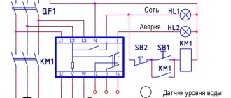
There are also special three-phase solid-state relays for reversing motors that have two control inputs.
An example of turning on a three-phase relay is in the photo below:
Turning on a three-phase solid state relay
As you can see, the relay is not entirely three-phase; one phase is constantly supplied to the motor, which can cause danger.
Its connection diagram is printed on the relay body, where everything is clear. The relay is reversible, and it has two inputs - Forward and Reverse (Forward/Back). To reverse, phases L1 and L2 are swapped.
Important - there is no blocking inside the relay from simultaneous activation in both directions, and it must be provided in hardware (locking contacts of buttons/relays) and software (if control is from the controller). If this is not provided for, then a situation is likely where power outputs 1, 2, 3, 4 will be short-circuited