A Solid State Relay (SSR) or Solid State Relay (SSR) is an electronic device that performs the same functions as an electromechanical relay, but contains no moving parts. Commercial solid state relays use semiconductor device technologies such as thyristors and transistors.
That is, instead of moving contacts, TSRs use electronic semiconductor switches, in which the control circuits are galvanically isolated from the power switched circuits. Fortunately, now there are no problems purchasing switching field-effect transistors. Thus, to build a solid-state relay, we need a MOSFET (Metal-Oxide-Semiconductor Field-Effect Transistor) transistor, the Russian equivalent of the term is MOS transistor or insulated gate field-effect transistor, and an optocoupler. On the pages of the site there are articles devoted to transistor switches with optical isolation - “AC transistor switch”
This article discusses a key for switching alternating current. Using SMD components according to this scheme, it is possible to produce an alternating current SSR. Some of the parts are mounted on a printed circuit board, which is attached to an aluminum support. Transistors are mounted on the substrate through mica spacers. It is better to take capacitor C1 either tantalum or ceramic. Its capacity can be reduced. Another article - “Transistor switch with optical isolation”
In this circuit, bipolar transistors of different structures are used as switching transistors.
There is another circuit of a galvanically isolated switch on a mos-transistor with protection against the maximum load current. It was discussed in the article “Powerful DC switch on a field-effect transistor”
All this is good if the voltages with which SSRs implemented on MOSFETs operate allow these field-effect transistors to be controlled. But what about voltage switching, for example 3.3 volts. This voltage is clearly not enough to open the field effect transistor. We need some kind of converter capable of raising the control voltage to at least five volts. Using a classic pulse converter for relays is too cumbersome. But there are other converters - optical, for example - TLP590B .
Pass-through and crossover switches
I have an article on this issue. It says that if you need to control the light from 2 places, pass-through switches (or switches, as people say) are used. To each of them you need to lay three wires.
The scheme will be like this:
Classic lighting switching scheme from two points with pass-through switches
If there are 3 or more light control points, you need to install cross switches (except for the two pass-throughs at the edges of the circuit), with 4 wires laid to each of them:
Circuit with a cross switch for turning on lighting from three places
If you need control from 4 places, but you need 2 pass-through and 2 cross switches, respectively:
Scheme of two pass-through and two cross switches for turning on the light from four places
And so on, the number of cross switches increases.
Disadvantages of circuits with pass-through and crossover switches
Some disadvantages of classic circuits with switches may seem unobvious or insignificant, but I will still list them.
- Pass-through and cross-over switches have a higher price tag than regular switches.
- They are often out of stock in stores.
- More wiring required.
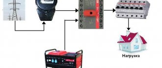
Where is the Starter Relay for VAZ 2115 Injector?
Starter relay VAZ 2115
The most likely cause of starter failure is electrical damage.
When the engine starts unsuccessfully for the first time, most people look for a problem in the starter, which is not always correct. The operation of the starter directly depends on the relay, contact connections and the availability of the necessary electricity. To check if the electric starter is working, it can be powered directly from the battery by connecting the positive wire from the terminal.
This way, you can start the engine to continue driving with a faulty starter power system. Many people try to find a VAZ 2115 starter relay in a car, where there is a component of the car’s electronic system, but the search does not produce results. This happens for the simple reason of its absence.
Perhaps the VAZ manufacturer is already equipping the new series of cars with a starter relay, but previous versions of these cars were manufactured without it. This is not critical, since the cost is negligible and the benefits are immediately visible; you can install it yourself, without the skills of an electrician.
Why is it necessary to install an additional VAZ 2115 starter relay? An additional relay ensures more stable operation of the starter with additional electrical equipment. Thus, the starter works even with a weakly charged battery, the backlight on and at low temperatures.
VAZ 2115 does not turn the starter, fix the problem
Installing the relay
for
starter
and 2110.
Do not confuse the VAZ 2115 starter relay with the repeater, which is located on the starter and performs the function of pushing and retracting the mechanism for engaging the starter teeth and the flywheel. Thus, a normal car start. Retractor malfunctions are expressed in the following manifestations:
- After the engine has started successfully, you may hear the starter whirring.
- Turn the ignition key with a simple click, the starter does not work
- try to start the engine with the key
Such manifestations are characterized by a violation of the starter and replacement of the relay.
Repair of the retractor starting relay VAZ 2115
First remove the starter by unscrewing the mounting bolts and before disconnecting the battery. Remember. The main thing. ensure the safety of repairs. After successfully removing the electric starter, you need to unscrew the solenoid relay bolts.
In most cases, the relay relay will not fold, but it can still be repaired. To do this, you will need a screwdriver, a soldering iron, a copper winding, a core, which, if you look, may turn out to be intact. In this case, you don't need to change it.
When soldering the wire with a soldering iron, you can move on to expanding the coil body. By separating the coil, you can determine its damage and replace the necessary elements.
Read the same, other reviews
- Replacing a VAZ 2114 cluster starter
Light control using pulse relays
Let me remind you that a pulse (bistable) relay is a relay that changes its state every time it receives an action from the switch.
We can say that a pulse relay divides the frequency of incoming pulses by two.
Read my old article on the design and connection of a pulse relay (bistable switch) from the Belarusian company Euroavtomatika FiF.
By the way, I also have an article on F&F - Voltage control relay EuroAutomatika F&F CP-721.
A big plus of a pulse relay is that you can connect as many switches (more precisely, non-latching buttons) to its input as you like, within reasonable limits.
Minuses -
- We depend on the controller and its software, which can fail due to interference and other influences, including service life.
- Not everyone likes the fact that some kind of automation decides when the lights should be turned off. Some people want to be in complete control of the situation, rather than waiting for the lights to go off on a timer. Or won't it turn off? Is the counter ticking?
- Not everyone likes it when non-latching buttons are used instead of the usual switches, in which everything is clear/understandable.
To be fair, I will say that such relays are now quite often installed in houses where there are rooms with several inputs/outputs.
However, what should you do if for some reason you cannot install a pulse relay? For example, the owner does not want to install buttons because he has already bought switches? But you can’t install crossover and pass-through switches, because... Are there 2 wires per switch in the wall? Or are there no crossover switches on sale (by the way, there are problems with this in Taganrog)?
I suggest a way out:
Types of TTP
When assembling solid-state relay circuits with your own hands, you should keep in mind that a variety of components can be used for these purposes. Nothing prevents the person who takes up the job from choosing modern field-effect transistors, for example, characterized by high performance and low power consumption. These elements are controlled only by potentials, providing the ability to switch sufficiently powerful consumers. Field structures such as MOSFETs are capable of switching load circuits whose power reaches tens of kW.
To independently manufacture a solid-state relay, it is possible to select other semiconductor structures capable of controlling power circuits: thyristors, for example, or bipolar transistors. The main thing is that they meet the requirements for the functionality of this circuit and the operating parameters of the elements included in its composition. Everything else depends on the preparedness and attentiveness of the performer.
Light control from several places using intermediate relays
An intermediate relay is, in principle, an ordinary relay that can perform the following functions (or one of them):
- Galvanic isolation,
- Transition from one voltage level to another (or from one type of current to another),
- Current amplification when the control current is much less than the contact current,
- Execution of logical functions,
- Reproduction of contacts (from one switching you can make 4, for example).
It is precisely the last function that will help us make pass-through and crossover switches on the relays, while using ordinary switches to control these relays.
The diagram will help you understand what is written:
Scheme with 2 pass-through switches and 2 relays. Switching on lamps from four places
That is, relays with their contacts imitate cross switches.
We can go further - we use 4 relays and 4 regular switches!
Circuit with 4 relays to simulate a circuit with 2 pass-through and 2 crossover switches
In the diagram, S1, S2, S3, S4 are ordinary familiar switches. People who are far from electrical and automation will find it easy and simple to understand this system.
Installation process
- We prepare the wiring. We crimp the connectors.
- The new VAZ 2110 starter relay must be mounted under the hood in a place so that it is definitely not flooded with water from puddles and rain. Many specialists install the relay on the stud of the washer reservoir.
- We bring the wire from the relay to the starter and connect it to the place of the red wire (it is with the “dad”). This is the connection point for the traction relay. This way we energized the coil of the new relay.
- We put a new wire with an 8 (mm) ring connector onto the positive terminal of the starter and tighten it tightly with a bolt. This wire goes to pin 87 in the new relay. I hope the VAZ 2110 starter connection diagram is clear to everyone.
- From the new relay on pin 30 we pull a wire with a “female” connector to the starter, to the place where the traction relay is connected.
- We connect the lead from pin 85 on the new relay to ground.
- We cover all wiring with a corrugated sleeve and thoroughly insulate it so that the wiring and contacts are not exposed to moisture.
- We do a test drive.
That's it, the additional VAZ 2110 starter relay (diagram attached) has been successfully installed.
Implementation of a lighting control circuit using intermediate relays
My regular reader Nikolai put together the proposed scheme. The task was to turn on the lights from four places in a large public room, and use switches rather than buttons. There were 3 wires connected to each switch, and touching the tiles was not an option at all.
Build process:
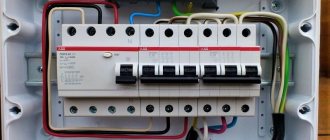
Assembling a circuit using switches and relays
Please note that Wago 221 5-pin terminals are used, mounted on a DIN rail through a special holder.
I have a lot of articles on Wago, here is the main one.
Assembling and debugging a lighting control circuit using a relay
Finder relays with a 230V coil are used as intermediate relays.
Lighting control circuit using a relay and modular contactor
Since powerful spotlights are used, the power of which is more than 2 kW, a modular contactor with a contact current of 25A is used. The contactor separates the “logical” and power parts.
Please note that this contactor has 3 positions – On, Automatic (coil controlled), and Off.
The scheme turned out to be as follows:
Scheme with 2 pass-through switches, 2 relays and a modular contactor
For those interested, read how a contactor is fundamentally different from a starter.
By the way, I used a similar modular contactor in a homemade ATS to connect a generator to the house. There I recommended connecting the coil in series with a resistor to reduce its heating when turned on for a long time.
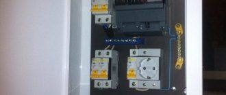
And the installation process in the utility room (electrical room) looked like this:
Installation of a lighting control system from 4 places
The cable used is NYM, copper monocore round.
Thank you for your attention, please share your opinions and ask questions in the comments!
Self-production
To make a current relay with your own hands, you need to stock up on a number of electronic components that form the basis of switching circuits. You will also need special materials from which the housing of the homemade relay will be made.
Electronic elements
The following common parts are usually used as electronic components used in the independent production of the simplest TSR sample:
- optocoupler pair MOS3083;
- triac brand VT139-800;
- bipolar transistor KT209 series;
- a set of resistors, as well as a zener diode and an LED that serves as an indicator of relay operation.
Solid state relay circuit
The listed electronic elements are soldered using a hinged method according to the circuit given in the sources. Along with other components, it contains a key transistor that supplies stabilized pulses to the control diode of the optocoupler pair.
The feeding moment is recorded by an LED element, the use of which in the actuator circuit allows for visual control.
Under the influence of these pulses, a semiconductor triac connected to the switched circuit is instantly triggered. The use of an optocoupler pair in such a circuit makes it possible to control constant potentials from 5 to 24 Volts.
A limiting chain of a resistor with a zener diode is necessary to reduce the amplitude of the current flowing through the LED and the control element to a minimum value. This circuit solution allows you to extend the service life of most elements used in constructing the circuit.
Housing design (filling with compound)
Filling the board with compound
To make the body of a prefabricated product, you will first need an aluminum plate 3-5 mm thick; it will serve as the basis for the electronic assembly. The dimensions are chosen arbitrarily, provided that they guarantee good heat dissipation to the surroundings. Another requirement for this part is a well-processed, absolutely smooth surface, polished with a special tool or sanded to a shine.
At the next step of preparing the body, the plate selected as the base is equipped with a border made of a strip of cardboard glued along the perimeter. The result will be a small box designed to accommodate a previously assembled electronic circuit. On its base, only the triac is rigidly attached to the components; all other elements are held within the housing due to their own connections.
To connect to the load and power supply, the corresponding conductors are led out of the box.
Subsequently, reliable fastening of the entire assembly is ensured by pouring a liquid compound into the box, previously prepared in a suitable container. After it hardens, you will get a monolithic structure that is not inferior to the best industrial designs in terms of protection from vibrations and other influences. Its only drawback is the impossibility of disassembling for the purpose of subsequent repair of the circuit.
Switching on from different places using relays and limit switches
At the request of reader Zoltan, I quickly sketched out a circuit that turns on and off two groups of lighting on the street and in the garage. In this case, pushbuttons, limit buttons and relays are used.
Scheme for turning on the light through the end buttons, Start, Stop buttons and relays
I took inspiration from here:
Algorithm and discussion of the scheme in the comments, starting January 16.
By January 26, after several intermediate options, the following scheme was born:
Lighting circuit on a relay with a motion sensor, limit switch and time relay
And then the author of the video sent Zoltan his diagram, here it is!
Automation circuit for turning on lights from different places
Modifications with variable modulator
A bistable relay with a variable modulator is well suited for detectors of different directions. Most modifications are available with open resistors. To assemble the relay yourself, it is more advisable to use a phase expander. The modulator in the device is installed immediately behind the contacts. It should also be noted that there are modifications to wired extenders. They have a low conductivity threshold. However, they can operate on AC power. The stabilizer for the relay can be selected on a conductor basis. The rated voltage of the element must be at least 24 V.
What can be done better
After completing the implementation of the first module of my computer, I came to the conclusion that some things could be done better:
- Probably, the number of relays used in the ALU could be reduced by combining addition and subtraction modules. I think that 8 relays could be saved this way.
- When working on the next module, you need to try to drill holes more carefully. This time, some of them came out with small (and one with large) cracks.
- Experience has shown that in our city it is not very easy to make high-quality laser engraving on brass. Apparently, next time I’ll have to try using photolithography to make inscriptions.
- It is likely that redundancy will have to be used for frequently switching circuits such as a clock generator, since relays have not proven to be very reliable.
Project website: github.com/Dovgalyuk/Relay Other computers:
- Harry Porter's Relay Computer: web.cecs.pdx.edu/~harry/Relay
- Relay Computer Two: www.electronixandmore.com/projects/relaycomputertwo/index.html
- RC-3 Relay Computer: www.computerculture.org/projects/rc3
- Edmund Berkeley's Simon Relay Processor: www.cs.ubc.ca/~hilpert/e/simon/index.html
- TIM: www.northdownfarm.co.uk/rory/tim/tim-8.htm
- DUO 14 Premium: www.ostracodfiles.com/ostracod/relay.html
- Relay computer "trainer": relaysbc.sourceforge.net
- i² 8-Bit Relay Computer: isquared.weebly.com
- Kilian Leonhardt's relay computer: www.relaiscomputer.de
- Der Relaisrechner: www.schlaefendorf.de/relaisrechner/dokumentation/index.html
Expenses
- Relay – 6120
- LEDs – 2660
- Toggle switches – 1510
- Power supply – 2520
- Wires and other parts – 1220
- Inscription plates (materials, engraving and fasteners) – 3340
- Case materials – 4300
- Total – 21670
So far it’s 2 times cheaper than Harry’s. This does not include solder and flux, sandpaper, faulty or damaged parts, or the cost of tools I acquired while making the case.