Connection diagram for a wired switch with 2 places. Do you know all the advantages and disadvantages of this wiring diagram? 3 important connection nuances
TEST:
If you decide to implement the wiring diagram described in this article, it will be useful for you to take a short test to make sure that you are ready to go.
How many contacts does the PV have?
- One;
- Three.
Explanation: The PV contains three contacts. One of them is “common”, and the other two are connected to the next PV.
There is no light in the room. First, the button of the first PV was pressed, then the second, and after that the first again. Will the light stay on after these steps?
- Yes;
- No.
Explanation: Yes, because after the third action, the phase voltage will reach the light bulb.
Can a PV circuit be implemented to operate two lamps?
- Yes;
- No.
Explanation: Yes, two-button PVs are used for this.
Electric lighting is an indispensable companion of any modern apartment. Light control is carried out using switches: there is one switch for one light source (ordinary light bulb, or several lamps). But this does not always suit the owners of the premises for some reasons. That is why the question arises, how to make it possible to turn on a light bulb from two or more places at once? In this material we will give a detailed answer to this question, and also provide a diagram of such a connection, and tell how the PV circuit works.
Why might you need a PV light circuit for 2 switches?
Situations when it is necessary to implement such a pass-through switch circuit in a room or other premises are very diverse. For example, a large bedroom. It is very convenient to place a light switch at each bed so that each resident has control over the lighting. Plus, you won't have to walk to your bed in the dark. When you enter the room, you turn on the light, and after you take your place in the bed, you turn it off.
It is also beneficial to use a similar scheme in small houses of 3-5 floors. If you make a light switch in the front door for each floor separately, this will result in the need to assemble unnecessary control circuits.
When using a pass-through switch from two places, the resident of the house will turn on the light when entering the entrance, and turn it off while on his floor.
Another example is a large office with several workstations. Having the ability to turn off/on the light from two or more points at once makes such an office much more comfortable.
Alternative
There is an alternative to pass-through redundant switches. An alternative option is characterized by the presence of bistable relays or LED electric lights, which are equipped with motion and light sensors:
- Bistable relays are preferable to use when it is necessary to use not only two, but three, four or more electrical switches to control lighting.
- Luminaires equipped with motion sensors are not as practical as walk-through switches. The number of stops, speed of movement and other parameters significantly influence the constant procedure of “turning on” or “turning off” electric lighting, which is an extremely inconvenient option.
What does a pass-through switch with 2 or more places look like?
Schemes of pass-through switches
It is impossible to distinguish a switch connected to such a circuit from the outside. This is an ordinary one-button switch/switch. There is a two- or more-button design, used when the lighting is more complex, and each button turns on a specific lamp. Instead of a push-button switch, a touch switch is used, but the principle of operation remains the same.
Precautionary measures
What measures should be taken when installing light in the house? Working with a voltage circuit requires a careful approach, taking into account safety rules.
To avoid injuries/accidents, before connecting the two-gang switch, you should properly turn off the current supply and check for voltage on the input cable.
- Safety regulations:
- It is better to begin work on installing sockets/switches before design renovation.
- Before starting installation, check the condition of the electrical wiring.
- Properly organize actions during daylight hours (it is more difficult to install in the dark).
- Be sure to check the serviceability of light bulbs and other parts.
- Use a voltage indicator to check that the current supply is disconnected.
- Turn off the circuit breakers or package switches on the home panel.
- In accordance with safety standards, it is correct to use red phase wiring.
- The neutral wire is blue.
- Carry out all actions with extreme caution.
- To avoid electric shock, special attention is paid to areas with high humidity levels.
- The power supply to the porch, bathtub, and basement requires the use of reinforced insulation.
- The light bulb is replaced when the electricity is turned off.
- Using a ladder, place an insulating mat at the base.
- After connecting the electrics, there should be no dangerous areas in the house.
- Contacts are connected in compliance with all technical standards.
Advantages and disadvantages of the PV scheme from 2 places
This connection scheme has advantages and disadvantages. They follow from the very essence of the operation of such a switch. The benefits include:
- Increased comfort level. From the examples given above, it follows that the use of the scheme allows you to get rid of the inconveniences that arise in everyday life;
- Ease of execution. This electrical circuit is very simple to implement and does not require the use of any additional specific equipment;
The only disadvantage of this implementation of lighting control is the excessive consumption of electricity. Let's remember the above example about the entrance. Having entered it, a person turns on the light, and having already climbed to his floor, turns it off. The lighting will continue to operate on all floors until the occupant of the building presses the switch. Such an expense cannot be impressive, and when it comes to small rooms, it is completely absent.
Preparatory work
No matter how many keys your switch has (one, two or three), the preparatory work will be the same.
To begin with, you need to install a general distribution box and a mounting box for the switching device in the room; it is also called a socket box:
- If the walls in your room are made of PVC, plasterboard sheets, wood or MDF panels, install a special bit with serrated edges on a drill and make a hole. Insert the mounting box into it and fix it to the wall using self-tapping screws.
- For concrete or brick walls, make a hole using a hammer drill or drill with an attachment that works on concrete surfaces. But in this case, the mounting boxes must also be fixed using gypsum or alabaster mortar
As a rule, the installation of holes is carried out simultaneously with the laying of grooves. This is done purely for aesthetic reasons; there is a lot of dirt from such construction work, and it’s better to spray it once and clean it up. Grooves are grooves in the wall surface into which connecting wires will then be laid. They can be done using various tools:
- Hammer and chisel. This is an old ancestral method, its advantage is the complete absence of costs for purchasing tools (every man has a hammer and chisel). The disadvantage of this method of gating is that it takes a lot of time and effort.
- Bulgarian. This tool is often called the worst of the best. It’s convenient that grooves can be made quickly and without much effort. But it is from the grinder that there is a lot of noise and dust, and besides, it is not possible to make grooves of the same depth along the entire length, and it is almost impossible to work with the grinder in the corners of the room. So choose such a power tool as a last resort.
- Hammer. All you need is to purchase a special attachment for it - a strober or a spatula. In all other respects there are no shortcomings, it’s fast, convenient, the grooves are more or less even.
- Wall chaser. This is the ideal tool for this type of work. Works efficiently, safely and quickly. The grooves are smooth, there is no dust, since the wall chaser is connected to a construction vacuum cleaner. They are comfortable to work with and the tool does not make much noise. The only drawback is the high price. But there are services where you can rent a wall chaser.
Briefly about gating walls using the tools listed above is described in this video:
It is necessary to lay two-core wires into the grooves and fix them with cement or alabaster mortar.
So, the preparatory work is completed, the boxes are mounted, the wires are laid, and you can connect the light bulbs and switch.
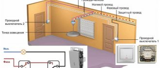
Scheme of a pass-through switch from two places
PV electrical circuit
The figure shows the simplest electrical circuit for controlling lighting from two places using pass-through switches. The numbers 1 and 2 indicate the switches themselves. The phase wire is highlighted in red - that is, the wire through which the voltage flows. The diagram simplifies a single lamp as a light source, but more complex lighting is allowed in its place.
The figure shows how the PV circuit works: when you press any of the switches, the light will turn off/on. If the first switch transmitted voltage to the lamp, then pressing the second switch will turn off the light - at this point the phase wire will be “broken.” The reverse is also true. The diagram shows the situation when both switches are off. The light will not be active in any button arrangement. But what will happen in other situations? Let's consider each of the possible options.
In this diagram, first the first switch was pressed sequentially, and then the second. The green arrow shows how the contact acts after pressing the second button. It cuts off the flow of electric current, so the light bulb becomes inactive.
Following this, the first switch was turned on again. The light bulb will light up again - the phase voltage will reach the light source. After pressing the first button, the light will go out.
This is how the electrical circuit of a pass-through switch works from two places to one lamp. Its mechanism is quite simple and understandable; it is briefly described as follows:
- If both switches are on, the light source is active;
- If one of the switches is on, the light source is active.
- Both switches are off - the light source is inactive.
How to connect a pass-through switch
Design Features
Two-key devices for turning on/off the load are structurally almost identical to single-key devices, the main difference lies in the switching mechanism. Below, Figure 2 shows the main design elements.
Figure 2. Main design elements
Designations in the photo:
- A – keys;
- B – external panel-casing;
- C – internal panel;
- D – switching mechanism;
- 1 – input;
- 2 and 3 – contacts for control wires going to the chandelier.
Now let's look at how the contact group diagram of the switching mechanism is arranged; it is shown in Figure 3.
Drawing. 3. Contact diagram of a two-key device
As can be seen from the presented diagram, the switching mechanism has three contacts, “1” is a common input, “2” and “3” are two control outputs.
Now that we have figured out the design of two-key switches, we can move on to their connection diagram.
Application of a switching circuit from 2 places
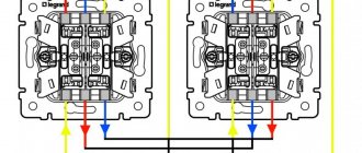
Each of the switches has two terminals. To implement the above-described scheme, it is necessary to find in each of them that contact terminal where the contact is fixed on one side. This terminal is called “common”. In one of the switches, phase voltage is connected to it, and in the other, a wire from the lighting source is connected.
The remaining terminals are connected to each other. The connection sequence is any. The blue color in the diagram indicates the neutral wire. It is routed directly to the light source from the junction box.
There are five wire connections in the junction box.
3 safety tips
When implementing an electrical circuit, you should remember 3 nuances:
- In order to determine which wire is phase, use a special probe.
- You should not use wires made of different metals when connecting them “twisted”. Due to the potential difference, a fire is provoked;
- When working, use thick rubber gloves.
Advice from professionals
In order not to get confused when installing electrical wiring, it is better to look for wires with different core colors. The phase, as a rule, is connected to a white or red wire, zero to a blue or black wire, and yellow, green or yellow-green color is used for grounding.
When laying wiring under a layer of plaster, it is worth keeping the wire layout. This may be needed in the future. The easiest way is to photograph the wiring that has not yet been walled up, marking the distance from the walls, ceiling, corners, window openings, and other landmarks directly on the wall with chalk or a marker.
Calculations of the wire cross-section should not be carried out at a minimum; it is better to give some margin. Then you won’t have a headache when buying a new large plasma panel or installing a dishwasher in the kitchen, and at the dacha, if necessary, you can safely connect a household welding machine or electric saw to the network.
Simple connection diagram from four places
The principle of operation remains the same. But the circuit also includes two additional crossover switches necessary to ensure the connections of all contacts.
PV connection diagram for 4 points
The operation of the cross switches is independent of the others. They can transmit voltage to the light source even if the pass-through switch buttons are in the inactive position. The schematic image shows that if the light is on, pressing any of the buttons will turn it off. The opposite is also true.
This scheme can be expanded to any number of lighting control locations. But the main principle remains the same: at the beginning and end of the path (to the light bulb) of the phase wire there are two pass-through switches. Between them are cross ones. Their number is equal to the number of desired lighting control points.
Series and parallel connection of lamps
Hello, dear readers of the sesaga website. ru. Today we will look at practical circuits for connecting incandescent lamps in series and parallel
In the article about connection diagrams for three or more lamps, I talked about a parallel connection, but I missed the serial connection. In this article we will look at both types of connections used in everyday life.
Let's go from simple to complex. An ordinary lamp on circuit diagrams is designated as follows:
The next point you must understand
and
remember
:
Connecting wires in the diagrams are shown as lines
.
The junctions of three or more wires are shown with dots
, and if the wires intersect without a connection, then a dot is not placed at the place of their intersection.
The picture below shows when the wires simply cross
, that is, they pass side by side and do not touch each other, and when the wires are already
connected to each other
, this is indicated by
the point
at the intersection.
Now let's look at the types of connections:
Series connection of incandescent lamps
Series connection of incandescent lamps is rarely used in domestic life. At one time I connected two lamps in series in my entrance, but this was an isolated case.
Here the situation was such that the entrance lamp burned out every month, and something had to be done.
Usually, in such cases, the lamp is turned on through a diode so that it is powered by a reduced voltage of 110V and lasts a long time. This is a proven option, but the lamp itself flickers and shines at full intensity.
When there are two in series, they are also powered by a low voltage of 110V, do not flicker, serve for a long time, shine and consume energy as one. Moreover, they can be placed in different corners of the room, which is also a plus. But I repeat - this is a rare case.
Look at the picture below. Shown here are two circuit diagrams for connecting incandescent lamps in series. The upper part of the figure shows the circuit diagram, and the lower part shows the wiring diagram. Moreover, for a better understanding, the wiring diagram is shown with a real image of the lamps and two-core wire.
Here in the brown line, HL1
and
HL2
are connected in series - one after the other.
Therefore, such a connection is called serial .
If you apply a 220V supply voltage to the ends of L
and
N
, then both lamps will light up, but they will not burn at full intensity, but at half intensity. Since the resistance of the lamp filaments is designed for a supply voltage of 220V, and when they are in the circuit in series, one after the other, then by adding the resistance of the filament of the next lamp, the total resistance of the circuit will increase, which means that for the next lamp the voltage will always be less according to Ohm's law.
Therefore, when two lamps are connected in series, the voltage of 220V will be divided in half, and will be 110V for each.
The following figure shows three lamps connected in series.
In this diagram, the voltage on each lamp will be about 73 Volts, since it will be divided between three lamps.
Another example of a series connection is New Year's garlands. Here, one 220V lamp is created from miniature light bulbs with low power supply.
For example, we take light bulbs rated at 6.3 Volts and divide them by 220 Volts. It turns out 35 pieces. That is, to make one lamp with a voltage of 220V, we need to connect 35 pieces in series with a supply voltage of 6.3 Volts.
P
.
S.
_
Since the voltage in the network is not constant
,
it is better to make calculations based on 245 - 250 Volts
.
As you know, garlands have one drawback. One of the lamps burns out, for example, the green channel, which means the green channel is not lit. Then we go to the market, buy green light bulbs, and then at home we take them out one at a time, insert a new one, and until the channel starts working, we go through it all.
Conclusion:
The disadvantage of a series connection is that if at least one of the lamps fails, all of them will not light, since the electrical circuit is broken.
And the second drawback, as you may have guessed, is the weak glow. Therefore, series connection of 220V incandescent lamps is practically not used at home.
Parallel connection of lamps
A parallel connection is a connection where all elements of the electrical circuit, in this case incandescent lamps, are under the same voltage. That is, it turns out that each lamp, with its contacts, is connected to both phase and zero. And if any of the lamps burns out, the rest will burn. It is this connection of lamps, designed for a supply voltage of 220V, that is used in home life, and not only.
The following figure also shows a parallel connection. Here all three lamps are connected in one place. This type of connection is also called a “star”
There are times when it is necessary to route wiring from one point in different directions.
By the way, it is the “star” that makes the wiring around the apartment when installing sockets.
Well, that's basically all. And as always, by tradition, a video about serial and parallel connection of lamps
Now I think you shouldn’t have any problems connecting lamps in series and parallel . Good luck!
Five most frequently asked questions
Is it possible to control several lighting sources from two places using PV?
Yes, such an implementation is possible. The double PV circuit for two lamps will differ only in that each switch will have not one button, but several (according to the number of lamps). Each button will only regulate the operation of the corresponding light bulb and will not affect the operation of the others.
Is it possible to control a light bulb from three or more places using PV?
It is impossible to implement such a scheme using only pass-through switches. To solve this problem, parallel switches are additionally implemented, which allow you to increase the number of lighting control locations to any desired number.
How is a pass-through switch different from a regular one?
The principle of operation of a conventional switch is quite simple - when you press the button, it either interrupts the electrical circuit or, on the contrary, transmits the electric current further. PV works more difficult. Pressing the button switches between different contacts. The final result (whether the light bulb is activated or not) depends on the position of the other switches.
What is the difference between a pass-through switch and a parallel switch?
A parallel switch, unlike a pass-through switch, contains as many as 5 contacts, which provide a more complex lighting control circuit, which has a much larger number of options. There are only three contacts in the PV, one is common, and the other two are used to transmit voltage or break the electrical circuit - this depends on the position of the button.
What should you pay attention to when choosing a PV?
When choosing a PV, you should pay close attention to the specific type of device. They may differ in their characteristics, as well as in shape. There are open type PV (for connection with open wiring) and closed type (for connection with wiring running inside the walls). The contacts of the device are designed for a specific electric current, so when choosing a model you should focus on the expected load.
How to connect 4 PV?
Four PVs are connected using crossover switches, as described above.
Safety conditions
How to make 2 switches for one light bulb? Installation of pass-through switches is possible with both open and hidden wiring systems. Installation can be carried out independently, only if you follow the necessary safety rules:
- Before starting installation work, it is necessary to turn off the power to the apartment.
- It is necessary to correctly determine the location of the phase and zero.
- The wires should be connected by neat twisting, while crimping and insulating them.
- It is recommended to firmly fix electrical accessories and branch boxes to surfaces.
- Based on the power of electricity consumed, you need to determine the power parameter of the lighting device and select a three-core cable of the required cross-section.
Important! Due to the design feature, there is no specific “on” or “off” position on the key of the backup electric switches. Based on the position of the electrical contacts of the other switch, the two connecting nodes of this system correspond to the “closed” or “open” position. Therefore, when the light is turned off, the key will be in a different position each time. This feature is not a problem and you can quickly get used to it.
Tags
two switches Which switches to use Pass-through switch 2 switches on one switch is impossible Which switches to use simple switches to organize Pass-through switch March switch single-key switch Connection diagram of two connection diagrams two connection diagram. Connection diagram of two Connection of two Connection of switches Connection diagrams and connection diagram of one for connecting wires Connection diagrams and luminaries LED Lighting devices LEDs Light LED strip Lighting fixtures
distribution box similar boxes double rooms larger socket input usual has switches