In this article we will look at the circuitry of various types of uninterruptible power supplies.
An uninterruptible power supply (UPS or UPS) is used to maintain the functionality of electrical appliances for a limited time during power outages. The devices are most often used in conjunction with servers, computers, various office equipment, etc. The circuitry of an uninterruptible power supply is determined by the conditions of its use: the connected power, the duration of maintaining the required supply voltage and some additional functions. The designation of the uninterruptible power supply on the electrical diagrams is shown below:
UPS connection
Most devices are equipped with a USB port for connecting to a PC. Therefore, when the main power source is turned off, the computer automatically switches to low power consumption mode. In order for the UPS to work consistently with a PC, it is enough to connect them through a free port, and install the driver that comes with the UPS on the PC. Also, do not forget that the load connected to the device must consume 1.5 times less energy (in watts) than the UPS power multiplied by 0.7. That is, a 1000 W inverter can be used to power a load with a power of up to 470 W (maximum 700). Below is the UPS connection diagram:
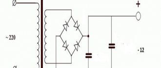
It is worth noting that connecting printers to a UPS is not recommended: when this device is connected to the network, a strong jump in energy consumption is formed, which the inverter will take as a danger and go into protective mode. A surge protector for UPS is not needed, since it has a built-in one. Below is a circuit diagram of a UPS of the simplest design.
Such a device is capable of producing an unstabilized voltage of 12 and a stabilized voltage of 5 volts. As soon as the power is turned off, the battery comes into operation (in diagram B1). If you need a stabilized voltage of 15 volts at the output, connect a pair of 12 V batteries in series, and also use a 7815 stabilizer (now 7805).
Yes, on the topic “how to protect it from 220V voltage surges?” Cheap uninterruptible power supplies do not provide any real protection. Yes, they can “absorb” some joules, but... in my practice there were several cases when, during a short-term power outage, less than a second, a cheap UPS killed the hardware connected to it: the inverter had already started, but the bypass (passing electricity through) was still did not turn off, and the output was the sum of the socket and the inverter. I don’t know what’s causing it, I’m guessing it’s due to the poor quality of mechanical relays.
Real protection is provided by constant double conversion uninterruptible power supplies, which have no bypass - they always rectify the incoming voltage to a constant 12...192V, and the output is always the voltage from the inverter. In terms of energy efficiency, of course, they lose, but in principle they do not have such a characteristic as “switching time to batteries”. Well, these don’t cost 20 kopecks, and they don’t make them for low power – there’s no point. If something bad comes from the supply network to such an uninterruptible power supply, its rectifier will first burn out. If the rectifier misses something, the surge will be damped by the battery, and the remainder will go to the inverter. The inverter will also likely burn out faster than it will burn out the connected load. Unless something completely indecent comes to the input, more than a thousand volts, to make its way right between the tracks on the board.
And further. In addition to power, the inverter has another characteristic - the shape of the output signal. The cheapest and worst ones give a square or meander signal. Inverters of the class from “bad, but not the best” to “above average” give a step signal, varying degrees of proximity to a sine wave. And only good, expensive inverters provide a “pure sine” signal, which they never forget to mention in the characteristics. But if the signal shape is not mentioned, then 95% that the inverter gives “steps”, and 5% - a meander.
From the square signal, “heaters” work, and hardware with switching power supplies work (all kinds of computers, not cheap chargers). But inductive hardware - electric motors, “heavy” transformer power supplies - do not work, work poorly, or work but get very hot and make unpleasant noise. And from the meander they can even die, because... the passage of a meander through a transformer produces a whole range of high-frequency harmonics for which the load may not be designed. For example, high-frequency harmonics can penetrate electronic control circuits through parasitic capacitances and be regarded as a control signal. (Somehow I’ve already drilled deeper than the declared horizon of “natural science brains”).
Car inverters never produce real pure sine wave! No, maybe somewhere in the USA there are such things, priced at 300 bucks, but not in Russia, where everything is Chinese and cheap. Therefore, do not connect anything that is very dear to you to the car inverter.
Household AC UPS circuit diagrams
The devices are connected to a regular single-phase 220 volt network. According to the functional diagram, there are three varieties:
- offline or backup – budget option;
- linear-interactive;
- online - with double conversion (the most expensive).
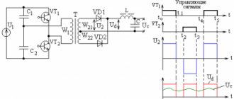
The block diagram of a double conversion uninterruptible power supply is shown below:
These devices, in addition to their high cost, are characterized by low efficiency: a lot of energy is converted into heat. What is the rationale for using such devices? The main advantage is the immediate response to the main power source being turned off. Next is a linear-interactive ups diagram:
This type of UPS is a conventional autotransformer in which the windings are directly connected, which ensures voltage stabilization. However, such devices are already included in most household appliances, and if there are small deviations from the rated voltage in your network, then there is no point in buying an expensive line-interactive product. You can get by with the usual offline, UPS 12 diagram of which is presented below:
Switching to backup mode in such uninterruptible power supply systems most often occurs using a mechanical relay, so as not to increase the cost of the design. If the part is of high quality, it will last for the entire period of operation of the unit. If the relay is cheap, then failure of the UPS most often occurs precisely because of it.
Laboratory power supply from UPS
In the article, the author tells how to make a laboratory power supply needed in amateur radio practice from a faulty or outdated uninterruptible power supply.
The main purpose of uninterruptible power supplies (UPS) is short-term power supply to various office equipment (primarily computers) in emergency situations when there is no mains voltage. The UPS includes a battery (usually 12 V), a step-up voltage converter and a control unit. In standby mode, the battery is recharged, in emergency mode, the voltage converter is turned on.
Like all equipment, UPSs fail or become obsolete. Therefore, they can be used as a basis for the manufacture, for example, of a laboratory power supply unit (PSU). The most suitable for this may be UPSs in which voltage converters operate at low frequencies (50...60 Hz), and they include a powerful step-up transformer, which can also work as a step-down transformer.
To manufacture a laboratory power supply, the KIN-325A UPS was used as a “donor”. During development, the task was to obtain a simple circuit, using as many elements as possible from the “donor”. In addition to the transformer and housing, powerful field-effect transistors, rectifier diodes, a quad op-amp microcircuit, an electromagnetic relay, all LEDs, a varistor, some connectors, as well as oxide and ceramic capacitors were used.
The power supply circuit is shown in Fig. 1. The mains voltage is supplied to the primary winding of transformer T1 (marked RT-425B) through fuse link FU1 and power switch SA1. Varistor RU1, connected in parallel to this winding, together with the fuse link, protects the power supply from increased mains voltage. Through the current-limiting resistor R1 and the diode VD1, the LED HL1 is powered, signaling the presence of mains voltage.
Rice. 1.
A powerful rectifier on diode assemblies VD2-VD5 is connected to winding II (with a tap in the middle, rated voltage 16 V) of transformer T1. Depending on the position of the contacts of relay K1.1, the rectifier operates as a full-wave rectifier with a common terminal of the transformer (shown in Fig. 1) and an output voltage of about 10 V, or as a bridge with an output voltage of about 20 V. The output voltage of this rectifier is supplied to the regulating element - field transistor
VT1. Capacitors C1 and C3 smooth out the ripples of the rectified voltage, resistor R2 is a current sensor. Resistor R17 ensures the minimum load of the voltage stabilizer in the absence of external load.
The low-power rectifier is assembled using diodes VD6-VD9 and smoothing capacitors C2 and C5. It powers the parallel voltage regulator on the DA1 chip, op-amp DA2, relay K1 and fan M1. The HL2 LED signals the presence of voltage at the output of this rectifier.
An adjustable voltage stabilizer is assembled on op-amp DA2.3 and transistor VT1. The reference voltage to the voltage regulator - resistor R11 - comes from the output of the stabilizer on the DA1 chip. The output voltage of the power supply from the engine of the trimming resistor R12 is supplied to the inverting input of the op-amp DA2.3. This resistor sets the maximum output voltage. The adjustable current limiter is assembled on op-amps DA2.1 and DA2.2. A voltage proportional to the output current from the sensor - resistor R2, is supplied to the voltage amplifier at the op-amp DA2.1 and then to the op-amp DA2.2, which compares it with the standard one supplied to its non-inverting input from the output of the resistive divider R4R7R8. Resistors R7 and R8 set the current limiting threshold.
Transistor VT2 controls relay K1. It will work when the voltage at the gate of this transistor exceeds the threshold value (for the transistor indicated on the diagram, the threshold voltage is 2...4 V). Trimmer resistor R19 sets the output voltage of the power supply unit, above which the relay switches the output voltage of the rectifier. Transistor VT3 together with thermistor RK1 controls fan M1. It turns on when the temperature of the heat sink on which the VT1 transistor and thermistor are installed exceeds a preset value. The threshold temperature is set by resistor R15. The thermistor supply voltage is stabilized by a VD11R16 parametric stabilizer. The excess supply voltage of relay K1 drops through resistor R13, and fan M1 - through resistor R18.
If the load current does not exceed the threshold value, the voltage at the non-inverting input of op-amp DA2.2 is greater than the voltage at the inverting one, at its output there is a voltage close to the supply voltage, therefore the VD10 diode is closed, and no current flows through the HL3 LED. In this case, the control voltage to the gate of the field-effect transistor VT1 is supplied from the output of the op-amp DA2.3 through resistor R14 and the voltage stabilizer operates. If the output voltage of the stabilizer is less than 4 V, transistor VT2 is closed and relay K1 is de-energized. In this case, the voltage at the drain of transistor VT1 is 10 V. When the output voltage is more than 4 V, transistor VT2 opens and relay K1 is activated. As a result, the voltage at the drain of transistor VT1 increases to 20 V. This technical solution makes it possible to increase the efficiency of the device.
When the load current exceeds the threshold value, the voltage at the output of op-amp DA2.2 will decrease, diode VD10 will open and the voltage at the gate of transistor VT1 will decrease to a value that ensures the flow of the set current. In this mode, current flows through the HL3 LED, and it signals the transition to current limiting mode. The limiting current is set by resistor R8 in the range of 0...0.5 A and R7 in the range of 0...5 A. Capacitors C4 and C6 ensure stable operation of the current limiter. Increasing their capacity increases stability, but reduces the performance of the current limiter.
The device uses fixed resistors - S2-23, P1-4 or imported ones, tuning resistors - SP3-19, variable resistors - SP4-1, SPO. In order for the scale of variable resistors that regulate voltage or current to be linear, they must be of group A. Thermistor - MMT-1. Resistor R2 is made from a piece of PEV-2 0.4 wire, 150 mm long. In addition to the function of a current sensor, it also works as a fuse in case of emergency situations. Oxide capacitors are imported; instead of non-polar ones, you can use ceramic K10-17. The fan is a computer fan with a current consumption of 100...150 mA, its width should be equal to the width of the heat sink. Relay - any, designed for a switching current of 10 A and a rated winding voltage of 12...15 V. XS2, XS3 - sockets or terminal blocks.
Most of the elements are placed on two printed circuit boards made of fiberglass foil on one side with a thickness of 1.5...2 mm. On the first (Fig. 2) rectifiers are assembled, transistors VT2, VT3 with their “surrounding” elements and some other parts are mounted. The printed conductors connecting the elements of a powerful rectifier are “reinforced” - pieces of tinned copper wire with a diameter of 1 mm are soldered onto them. The “standard” terminals of the T1 transformer are wired; they are equipped with two sockets. If you plan to use them, the corresponding plugs are mounted on the first board, which are unsoldered from the “native” UPS board.
Rice. 2.
The second board (Fig. 3) contains all the microcircuits, LEDs, and some other elements. On the side free from printed conductors, push-button switch SA1 (P2K or similar) is glued. The LEDs must fit into the “standard” holes on the front wall of the case, and a “standard” pusher is glued to the switch.
Rice. 3.
The first board is installed next to the rear wall of the case, the second - close to the front. To fasten the boards, two screws and “standard” mounting plastic stands on the top cover of the case are used. A VT1 transistor, a thermistor and a fan are placed on a finned heat sink with external dimensions of 30x60x90 mm (it is installed between the boards). Heat shrink tubing is placed over the thermistor and then glued to the heat sink next to the transistor. Since when the temperature of the thermistor changes, the field-effect transistor VT3 opens and closes smoothly, the fan begins to rotate and stops also smoothly. Therefore, transistor VT3 can noticeably warm up and cannot be replaced with a low-power one, for example 2N7000.
On the front panel (Fig. 4), variable resistors and connectors XS2 and XS3 are installed in the holes, to which resistor R17 and capacitor C7 are soldered. The block plug XP1 and socket XS1 are “native”, they are located on the rear wall in its lower part. The XS1 socket can be used to connect any device that operates simultaneously with a laboratory power supply, such as an oscilloscope.
Rice. 4.
The setup begins by setting the maximum output voltage. This is done using resistor R12, the slider of resistor R11 should be in the upper position in the diagram. If you do not plan to build a voltmeter into the power supply, resistor R11 is equipped with a handle with a pointer and its scale is calibrated. When transistor VT2 is open, by selecting resistor R13, the rated voltage is set on relay K1, and when VT3 is open, resistor R18 is used to set the voltage to 12 V on fan M1. The fan switch-on temperature is set with resistor R15.
To set up a current limiter, a series-connected ammeter and a load variable resistor with a resistance of 10...15 Ohms and a power of 50 W are connected to the power supply output. The resistor sliders R4 and R7 are set to the left position according to the diagram, the slider R8 is set to the right. The load resistor should have maximum resistance. When the output voltage is about 10 V, the load resistor sets the current to 5 A, and resistor R5 sets the voltage to 0.9...1 V at the output of op-amp DA2.1. Using a load resistor, increase the output load current to 6 A and, by smoothly rotating the slider of resistor R4, turn on LED HL3 (turn on the current limiting mode) and then set the output current to 5 A with resistor R4. When moving the slider of resistor R7 to the right (according to the diagram), the output the current should decrease to zero. In this case, resistor R8 can be used to regulate the output current in the range 0...0.5 A.
If you do not plan to build an ammeter into the power supply, the scales of these resistors are calibrated. To do this (in current limiting mode), the output voltage and load resistance are changed, the required current value is set and marks are placed on the scale. In this case, in the range of 0...0.5 A, the current is set by resistor R8 (resistor R7 should be in position “0”), and in the range of 0...5 A - by resistor R7 (resistor R8 should be in position “0”).
In current limit mode, you can charge batteries and rechargeable batteries. To do this, set the final voltage and charging current, and then connect the battery (battery).
A further direction for refining the proposed power supply is the installation of a built-in digital voltmeter, ammeter or combined measuring device.
Author: I. Nechaev, Moscow
Inverter
Its task as part of the UPS is to convert direct voltage into alternating voltage 220 V and supply it to the consumer. Sometimes the bypass mode is activated. This is when the inverter output voltage is generated from the mains voltage, i.e. the battery is not used. Thanks to this, switching to backup mode occurs instantly. Uninterruptible power supply inverter circuit (upper part - line filter, GV1 - battery):
We increase the operating time of the UPS. Battery selection
Autumn is approaching and energy problems are approaching. A completely typical situation is when the heating has not yet been turned on, and all the neighbors begin to heat themselves with electric fireplaces and various heaters, draining the already loaded network. Storms break wires, wires break, equipment is left without power. A life-saving uninterruptible power supply or UPS comes to the rescue. But what to do when a line failure lasts more than an hour, and the uninterruptible power supply exhausts its entire resource in tens of minutes? Increase the capacity of built-in batteries. Today I will tell you how to do this correctly and safely, as well as how to choose the necessary battery using a real example.
Just the other day, a rather trivial but interesting problem arose. A long-existing server rack with a small amount of equipment and an approximate consumption of 250-400 W is equipped with an IPPON Smart Winner Pro 2000 UPS. Its battery life is about an hour, and in the event of a longer power outage, a gas generator installed on the street was manually started. Objective: to ensure a stand's battery life of at least 6 hours at minimal cost.
The conclusion immediately arises to equip the generator with some kind of automatic start system, like this one. The plus is that the cost of such a modification is about 13 thousand rubles, and the minus is that regular maintenance and refueling of the generator is required. The human factor is added, which means the overall reliability of the system is reduced.
The second method, which was chosen for its simplicity and reliability, is to increase the battery capacity. In this case, it is enough to simply increase the battery capacity; fortunately, in this instance, the battery pack is remote and connected with a separate wire. Since standard batteries have a capacity of 9 Ah and are assembled into a 48 V battery, it is enough to replace them with similar gel batteries with a capacity of 40-50 Ah. Since the charging unit is equipped with a forced cooling system, such a load will not be critical and will only affect the battery charging time.
But what about those whose consumption is much higher and the requirements for battery life are noticeably different? For example, a rack is 1-1.5 kW and requires up to 24 hours of autonomy. In this case, the easiest way is to install uninterruptible power supplies for 10 minutes of operation and powerful generators with an automatic start system, which will start 5 minutes after the power is turned off. This whole system costs a significant amount of money, but sometimes the stability of operation pays for it.
I want to consider an intermediate option for a small office or private home when a reserve for a variable load is required, with a peak of 6 kW and an average consumption of up to 1 kW for a long time without external supply. It is possible to add a generator, then the system becomes completely autonomous.
As an uninterruptible power supply for myself, I chose the rack version of the UPS from the MicroART company. Fortunately, this copy worked for enough time and demonstrated trouble-free operation. In addition, it has a wide range of settings, allowing you to save battery life and use them correctly.
Explanation:
All office UPSs use gel batteries, which have many advantages: they are supplied charged, do not require maintenance, and the electrolyte is in a thickened state, which means it will never spill. But all uninterruptible power supplies support increased voltage on the batteries, which allows you to use 100% of the capacity and charge them as quickly as possible. It is precisely the last two points that significantly reduce the service life of batteries, bringing them to the figure of 2-3 years before failure.
I wanted 5-7 years, or better yet 10, without replacing batteries. And here we come to choosing the type of batteries.
AGM batteries
AGM technology uses a porous filler of fiberglass housing compartments impregnated with liquid electrolyte. The micropores of this material are not completely filled with electrolyte. The free volume is used for gas recombination. Sealed, maintenance-free, do not require a ventilated room for installation. AGM batteries work well in recharge mode (buffer mode) with a service life of up to 10-12 years. If they are used in a cyclic mode (i.e., constantly charged and discharged to at least 60% -80% of capacity), then their service life is reduced by almost two to three times. Service life with full autonomy is up to 3 years. Recommended for backup uninterruptible power supply.
GEL
A substance based on silicon dioxide (SiO2) is added to the liquid electrolyte, resulting in the formation of a thick mass resembling a jelly in consistency. This mass fills the space between the electrodes inside the battery. During the process of chemical reactions, numerous gas bubbles appear in the thickness of the electrolyte. In these pores and shells, hydrogen and oxygen molecules meet, i.e. gas recombination. Almost all evaporation is thus returned back to the battery and this is called gas recombination. The separator in gel batteries is also unusual - microporous duroplasty, due to aluminum additives it is highly resistant to aggressive environments, has high temperature stability and mechanical strength; the latter provides high vibration resistance and impact resistance of the structure. In the production of gel batteries, high-purity lead is used - this increases the performance characteristics of the battery several times. Service life with autonomy is up to 4 years, with backup power up to 12 years. Recommended for backup uninterruptible power supply.
GEL and AGM batteries are practically indistinguishable in appearance and have fairly similar characteristics. Further more interesting.
Armored
The basis of the armor plate is a cover (shell) made of non-woven microporous plastic in the form of a series of parallel tubes. The active mass is contained inside the tubes. The current-carrying part of the plate is a rod frame pressed into the active mass, cast from a lead-antimony alloy. The rod frame is injection molded, which eliminates the formation of cavities and other casting defects in the conductor rods, significantly increasing the service life. The microporous shell reliably protects the positive active mass from shedding and sliding throughout the entire period of battery operation. Recommended for full autonomy and/or backup systems. The service life of armored batteries under autonomous conditions is at least 10 years with proper operation (or 1500 cycles of 80% discharges), or 15 - 17 years with backup power. Supplied dry-charged.
Lithium iron phosphate (LiFePo4):
Sealed batteries manufactured using lithium iron phosphate technology. Recommended for full autonomy and/or backup systems. The service life of lithium iron phosphate batteries under autonomous conditions is up to 20 years with proper operation (or 5000 cycles of 70% discharges), or 25 - 30 years with backup power. Supplied complete with BMS. These batteries have a number of important advantages and are the most promising batteries in the world.
Choice
Everything points in favor of Lithium Iron Phosphate batteries (LiFePo4), but the initial investment is quite large, although the advantages are undeniable: no acid, sealed, maintenance-free and the lowest cost of the charge-discharge cycle. Taking into account all the pros and cons, I decided to go with dry-charged armored batteries.
Preparing and assembling the battery
Since the armored batteries that I chose are supplied in 2V cans, and I needed to get 24V, I had to assemble the battery myself from 12 pieces. The first step was filling with electrolyte. The procedure is associated with a health risk, so it is necessary to use protective equipment: glasses or an eye mask, a respirator, rubber gloves, rubber boots. I also added a rain cover in case the electrolyte, which contains acid, spills. It is also best to fill batteries on a rubber or plastic mat so that if the electrolyte is spilled, there will be no traces left on the floor.
To fill the electrolyte, I used this acid-resistant hand pump.
Refilling the battery itself is quite simple, but taking into account 12 cans it takes a lot of time. Soda is in the frame for a reason. From the chemistry course we know that it is much more effective not to wash off the acid with water, but to neutralize it with soda, so for safety reasons it is better to keep an open pack of soda nearby.
After filling the batteries with electrolyte, it is necessary to recharge the battery no later than after 3 hours. The charging procedure itself must be carried out with an appropriate charger with a current of 10% (0.1C) of the battery capacity. For example, if the capacity is 210 Ah, then the maximum charging current should be no more than 21 A. Thick jumpers are used so that they do not become a bottleneck when large starting currents flow. In addition, when current flows through thin wires, they noticeably heat up, which can lead to premature wear of the batteries or a fire. After all, heating the battery from +25 to +35 degrees reduces the battery life by half.
The next step, which makes it possible to turn serviced batteries into low-maintenance or completely maintenance-free ones, was the installation of recovery plugs. The hydrogen released during charging, rising into such a plug, combines with oxygen and flows back into the battery. Before installing such plugs, you need to fully charge the battery and let it sit for several days, since at first there may be increased gas formation, which such recuperators are not designed for. If we neglect this situation, then a sad result is possible: overheating of the recuperator.
As a result, the battery acquired this appearance and will only require a preventive check of the voltage difference between the battery banks once a year, and a check of the electrolyte level once every 6 years. If the voltage of different batteries begins to “scatter”, then it is necessary to carry out an equalizing charge (charge with increased voltage). If the electrolyte level is lower, just add distilled water.
Here is the advantage of such a solution: for sealed batteries (GEL and AGM), hydrogen, despite internal recovery, also slowly evaporates, but it is no longer possible to add water and such sealed batteries have to be thrown away much earlier.
The stored energy of this particular assembly is 5040 Wh, and without any significant losses to the health of the battery, half can be spent. That is, two or three laptops in normal operation can last a day and still have some energy left. If you add to this an external generator or solar panels, the system becomes completely autonomous and will allow you to operate for more than one year.
Conclusion
The inverter with an external battery pack turned out to be larger than a standard compact UPS with built-in batteries, but the almost endless capacity of external batteries allows you to significantly increase battery life. And if the emergency power supply time from the UPS is minutes or tens of minutes, then when using an inverter with external batteries, the battery life is calculated in hours or days.
If it’s interesting, I can compare two devices head-on: the Powercom Smart King SMK-2000A-RM-LCD UPS and the SIN Energy Pro HYBRID MAP inverter with an external battery pack.
UPS transformer and its application
One of the options for using this uninterruptible power supply element is the manufacture of a power supply. Remove the transformer, use an ohmmeter to find the winding with the highest resistance: 220 V is supplied to it. Now measure the voltage at the remaining terminals and find 15 V. All that remains is to connect a rectifier bridge and a smoothing capacitor to it - the block is ready. The simplest diagram for connecting a transformer from an uninterruptible power supply:
Such a homemade device can be used, for example, to recharge a laptop.
Possible problems and nuances
The described process of manufacturing an uninterruptible power supply from a transformer has, however, significant disadvantages . In particular, they are associated with a typical voltage limited at the output to 15 V. When connecting a certain load to the resulting power supply, it should definitely “sag”.
In this regard, it will be necessary to experimentally select the voltage required at the output, which will require certain skills and knowledge, and is also associated with certain risks.
Thus, although it is absolutely easy to make , it is important to have at least basic knowledge in physics and electronics, as well as strictly follow safety precautions, since any work with electricity is potentially associated with serious risks to life and health.
see also
Comments 24
Do coolers work in all modes? Both from the network and from the battery?
Hello, they definitely work from the battery, I don’t remember exactly from the mains, they always work or turn on, I didn’t really test them in this mode
Good afternoon. And if you connect a 60 Ah battery from a car to such a factory UPS and the load is 50 W (circulation pump), are any modifications required or will the standard UPS circuit work normally?
Up to 100 watts will turn off because it will think that nothing is connected. You need to desolder the element. Also, weak charging will not charge 60ah well, since the capacity is large. and this is how it should generally work.
I found an Ippon Smart power pro 2000 UPS. The output power is written as 2000VA. I tried to connect it with a 12V power supply, the lights blink once and that’s it. I found detailed specifications, and it turns out that two batteries inside were 12V connected in series, so it requires 24V. And now the question is, I have 12V in my car, is it possible to somehow make it work from 12V or should I look for another UPS? Thank you in advance.