Faulty vehicle wiring leads to serious problems during the operation of the car - from incorrect operation of sensors and devices, on-board computer and automation to complete failure of expensive electrical equipment. Remember that a short circuit in the on-board circuits can lead to a fire in the vehicle. Therefore, faults in electrical equipment and electrical equipment should be eliminated immediately when they are detected - there is no need to put off repair work “on the back burner”.
You can repair car electrical wiring either yourself or at a car service center. The main difficulty lies in finding faults - breaks, failed relays, fuses and blocks, breakdowns of individual elements and auto electrical devices.
Common machine electrical faults
Auto electrics include various systems, parts, devices and elements of the vehicle - the ignition system, battery and generator, on-board computer circuits, fuses, sensors, relay blocks, various electronic sensors, auto lights, as well as auto electronics - climate system, audio system, automation and systems security. It is necessary to take into account the peculiarities of automotive electrical wiring in order to quickly find and eliminate a malfunction in the on-board network.
Common electrical problems include:
- Battery failure. This may be a consequence of insufficient electrolyte density, damage to the case with electrolyte leakage, destruction of the plates, or significant oxidation of the battery terminals.
- Generator breakdowns - winding breaks, problems with the voltage relay, failure of the diode bridge, wear of brushes and bearings.
- Problems with the ignition system. We are talking about malfunctions of spark plugs, ignition coils, an open circuit or oxidation of the contact group.
- Deformations of electrical wiring - oxidation at connection points (inputs, contacts, terminals), breaks, destruction of wire insulation, short circuit of wiring, violation of the integrity of twists.
- Failure of electronic components. This refers to malfunctions of various electrical devices in circuits, devices and electrical equipment of a car (conductors, diodes, fuses, capacitors).
What should be the resistance of high-voltage ignition wires?
In order to obtain the most complete information about the serviceability or malfunction of a high-voltage wire, a method of measuring its physical parameters is used.
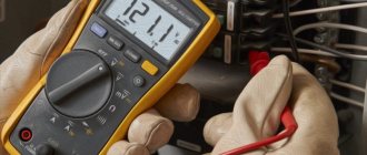
The simplest electrical measuring tool that should be in the trunk of any car is a multimeter. A simple small multimeter made in China is a little larger than two matchboxes in size and costs about 300 rubles.
In high voltage wires, two main parameters are checked: the resistance of the current-carrying conductor
and
insulation resistance
. The second parameter cannot be measured using a conventional multimeter; for this you need to have an expensive megohmmeter, since the insulation resistance must be several hundred megohms.
The resistance of the center conductor should be in the range from zero to several kiloohms. This depends on the type of high-voltage wires and the presence of limiting resistance in the ignition system.
Limiting resistances began to be used when cars began to be equipped with radio receivers. They significantly reduce the level of radio interference. In addition, they have another important function of protecting the ignition coil and control circuit from breakdown in the event of an overload in the high-voltage circuit. This is possible if the spark plug has a short-circuiting deposit, as well as if a high-voltage wire breaks down on the car body.
In many cars, limiting resistances are placed in a slider; in some cars, spark plugs have a limiting resistor. Sometimes resistors are inserted into the spark plug caps. But most cars use distributed resistance inside high-voltage wires.
In other words, the current-carrying core of a high-voltage wire is made of a conductor with high resistivity:
- nichrome, an alloy of nickel and chromium;
- cotton threads impregnated with a soot solution with a resistance of about 20 kOhm/meter;
- polymer conductive material with a resistance of about 15 kOhm/meter;
- fiberglass coated with graphite.
Sometimes such a conductor has the shape of a spiral, as in electric stoves.
To check high-voltage wires, the multimeter must be switched to resistance measurement mode at a limit of 20 kOhm. Next, connect the probes of the device to the opposite terminals of the wire.
The measured resistance should not exceed a resistance of 20 kiloohms (usually this value ranges from 500 to 3000 ohms). For ignition wires with distributed resistance, its value depends on the length of the high-voltage cable.
How to check wiring
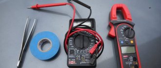
You can diagnose electrical equipment using a voltmeter, ohmmeter or multimeter, or special diagnostic stands. Computer diagnostics are also carried out, during which error codes and main indicators of the machine’s on-board network are read. To independently check circuits and troubleshoot electrical faults, one multimeter or signal lamp is enough.
We use a multimeter
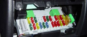
Fuses in the on-board network are considered the “weakest” link in terms of durability. In case of emergency situations (for example, in the event of a short circuit), the safety elements “take the blow”, protecting the rest of the electrics and electrical equipment of the machine. Fuses cannot be restored and must be replaced during repairs.
Checking the voltage
Before checking the wiring in the car, it is necessary to measure the voltage of the electrical circuit between individual components and electrical equipment. You can call like this:
- Set the multimeter to voltmeter mode.
- Connect one probe of the measuring device to the “minus” of the battery or to the ground of the machine.
- Connect the second probe to the supply wire of the circuit.
If a certain value appears on the device display, then there is voltage in this section of the electrical circuit. You can compare the values with those required according to the vehicle's owner's manual.
Looking for a short circuit
After measuring the voltage, search for short circuits. This will require either a multimeter or a pilot light. As for the lamp, if the wiring is in good condition and there is no short circuit, it should not light up.
A short circuit in the wiring, as well as a lack of voltage (zero or infinite resistance in the electrical circuit), indicates a malfunction in one of 2 components:
- Consumer - electrical equipment, devices, fuses, blocks.
- Wiring – broken or shorted wires, poor wiring contacts at the point of connection with the consumer.
Checking for a short circuit can also be done in voltmeter mode. To do this, it is necessary to remove all fuses in the area being tested and connect the probe to the terminals of the fuse element. The value “0” on the screen indicates the presence of a short circuit in the circuit. If, when you try to move the wires, voltage appears in the circuit, then the short circuit is caused by the wiring and the wires will need to be replaced.
Checking the quality of grounding
Cars use a single-wire wiring diagram - this means that the “minus” goes to the ground (body) of the car. However, corrosion of metal parts, their oxidation and destruction, “loosening” lead to grounding failure and, as a consequence, to disruption of on-board circuit contacts.
Checking the grounding, as well as other electrical elements of the car, is carried out using a multimeter. The procedure is as follows:
- Disconnecting the battery.
- Connecting one multimeter probe to the body (metal parts) of the car.
- Connecting the second probe to the grounding element or wiring connection.
Read also: Copper etching at home
The value displayed on the device screen should be compared with the factory data (car operating manual). If the values diverge greatly, then it is necessary to restore the grounding - clean the metal at the connection point, check the reliability of the fastening.
Checking the integrity of the circuit
The connection of wires in the electrical circuit of cars is one of the most vulnerable points in the entire electrical system of the car. In addition to the destruction of insulation, loss of integrity and breaks at the connection points, oxidation of the contacts also often occurs here. Defects can be determined not only using a measuring device, but also visually. If the integrity of the circuit is broken precisely at the connection point, then soldering of wires with connectors will be required. Otherwise, you need to find the damaged area, which will require a signal lamp or multimeter.
Technological instructions of AVTOVAZ
Below are general methods for checking electrical continuity, checking for shorts using an ohmmeter and a voltmeter.
Electrical continuity check
Loss of electrical circuit integrity can be caused by the following reasons:
- disconnecting the harness block;
- weak connection of the harness block;
- contamination, oxidation, corrosion of contacts;
- deformation of contacts;
- wire damage.
Check the continuity of the circuit in the following sequence:
- Disconnect the earth wire terminal from the battery.
- Visually check that the harness connectors are connected on both sides of the electrical circuit and that the locking latches are latched.
- Disconnect the pads, visually check the contacts for dirt, corrosion, and deformation.
- By pulling the wires next to the block, make sure that the wire and the terminal are tightly pressed together and that the terminal is fixed inside the block.
- Using a probe of a given diameter and length corresponding to the size of the contact in the mating block, make sure that the terminals of the harness blocks provide a reliable connection (the terminals are not recessed in the block, the probe fits tightly into the terminal).
- Using an ohmmeter, measure the resistance of the circuit between the pads. The resistance of a working circuit should be less than 1 ohm. To avoid damage to the terminals, it is allowed to use probes of a given diameter for measurements that correspond to the size of the contacts in the mating blocks.
Checking the circuit for short to ground
Perform the check in the following sequence:
- Disconnect the connectors on both sides of the electrical circuit.
- Connect the probe, one end connected to the “+” of the battery, to the terminal of the circuit being tested. If the probe lights up, it means that the circuit being tested is shorted to ground.
To avoid damage to the terminal, the probe must be connected using a probe of a given diameter that matches the size of the contact in the mating block.
Checking the short circuit to the on-board network
Perform the check in the following sequence:
- Disconnect the connector on one side of the electrical circuit.
- Connect the probe, one end connected to ground, to the terminal of the circuit being tested. If the probe lights up, it means that the circuit being tested is closed to the on-board network.
- Reconnect the disconnected block.
- Disconnect the connector on the other side of the electrical circuit. Perform check 2.
To avoid damage to the terminal, the probe must be connected using a probe of a given diameter that matches the size of the contact in the mating block.
Measuring voltage at wiring harness contacts
Perform the check in the following sequence:
- Disconnect the connector on one side of the electrical circuit.
- Connect the positive cord of the voltmeter to the terminal of the circuit being tested, the negative terminal to the vehicle ground. Record the voltage value.
To avoid damage to the terminal, the positive cord of the voltmeter must have a probe of a given diameter that matches the size of the contact in the mating block.
Let us remind you that it is more convenient to carry out wiring diagnostics when you have the car’s electrical circuit diagrams at hand (for Lada XRAY, Vesta, Largus, Granta, Kalina, Priora, Niva 4×4).
Key words: universal article
0 0 0 0 0 0
Share on social networks:
Car electrical wiring repair
You can check and restore the car's electrical wiring yourself or at a car service center. After identifying faulty areas where there is damage to the wires, a short circuit or a break, they are soldered or completely replaced. Conventional twisting followed by crimping is not a full-fledged repair, but only a temporary measure - take this into account if you do not have the opportunity to solder the break points.
Wires are selected with the same characteristics as the existing damaged ones (resistance, metal). You should not install too long wires with a “reserve”; twisted open wiring under the influence of negative factors (temperature changes, moisture, dirt) is destroyed faster - this can lead to a short circuit. When replacing wiring harnesses with connectors, make sure that the contact groups are completely free of oxidation before work.
Mounting blocks located in the engine compartment are also considered a vulnerable element of a car's electrical system. Due to the destructive effects of temperature and moisture changes, damage to the protective coating and subsequent defects in tracks, connectors for connecting wiring harnesses, relays, and capacitors are possible. Repair of mounting blocks, consisting of circuit boards, fuses and electrical components, includes soldering to restore tracks and coating with a special protective varnish, as well as replacement of faulty elements and wiring, connectors, cleaning contact groups from dirt and oxidation.
Rules for using the dialer
The only rule that needs to be remembered is that the dialing process is allowed only in a completely de-energized circuit.
Note! If you check live wires, you can get an electric shock and, in some cases, cause a fire. Below we describe in detail how to check the wire with and without a multimeter. Below we describe in detail how to check the wire with and without a multimeter
Below we describe in detail how to check the wire with and without a multimeter.
How to properly test wires (with a multimeter and without instruments)
Step-by-step work process:
- before starting work, you must turn the multimeter handle to the desired position;
- connect the ends of the probes to the required sockets. The black probe goes into the socket marked COM (in some cases indicated as “*” or ground point), and the red one goes into the socket marked Ω (sometimes indicated as R). It must be emphasized that the symbol Ω can be drawn either alone or in combination with the designations of other signs (V, mA). This arrangement of wires will help maintain polarity when making future measurements;
How to connect probes
- turn on the multimeter. Basically, there is a separate button for this or work can start automatically when the handle is turned to the required position;
- close the measuring ends to each other. If a beep is heard, the device is working correctly;
- take the wire to be tested (strip it of insulation in advance). Touch the exposed parts of the cable with measuring probes;
- If it is working properly, a sound will sound and the multimeter readings will be zero or show resistance. If the screen shows 1 and there are no sounds, it means that the tested cable is broken.
You can ring the wires without using a multimeter. To work you will need:
Diagram of a device with a light bulb
- a classic battery (it is advisable to take a 4.5-volt square battery);
- a regular 4-volt light bulb, through which the linear section of the cable is diagnosed (monitored);
- A pair of jumper cables and a breathtaking looking connector.
After preparing the tools for work, you need to use them to assemble a simple measuring circuit. If the circuit is correctly assembled and the wire is in good condition, the lamp will work. If there is a defect in the area, the light will not light up.
Replacing car wiring
When replacing wiring in a car, be sure to turn off the power, including disconnecting the battery. Of course, this is not a precaution against electric shock, but protection of the vehicle’s electrical equipment from possible short circuits that may occur during repair work.
Sometimes the replacement can be completed in 10-15 minutes - for example, if the wires of the “battery-generator” supply circuit are damaged. If the integrity of the wiring in the cabin is damaged, there are problems with grounding, or a short circuit in the on-board computer circuit, then the work will take much more time. And the main thing here is not to make a mistake, since incorrectly connecting the wires (for example, if the polarity is reversed) can cause a short circuit, damage to expensive electrical equipment and even a fire. If you do not have experience in electrical engineering and electrical installation work, it is better to contact a specialized service for the services of a professional auto electrician.
Many car enthusiasts, when problems arise with electrical wiring, immediately begin frantically looking for a familiar auto electrician to solve the problem, citing the fact that they do not understand electricity. In fact, there is nothing difficult about carrying out electrical diagnostics yourself. To do this, you will need a multimeter and a little knowledge, which we will try to outline for you in this article. Read the information below and you will not have any questions about how to find a short circuit in a car or, conversely, how to find a broken wire in a car.
High-voltage wires VAZ 2115
Automotive high-voltage (HV) wires play an important role for internal combustion engines, since they help transmit high current from the ignition coil to the spark plugs. The serviceability and efficiency of the wires determines the timeliness and intensity of ignition of the fuel-air mixture, and therefore the correct and uninterrupted operation of the engine. Despite their simplicity, wires have many different “sores” and can cause a lot of troubles to their owner, which in one way or another will affect his nerves and pocket.
Connection
The order of connecting high-voltage wires must be strictly sequential, since each cylinder of the engine corresponds to a specific socket on the ignition module. Considering that there is a numbering of the sockets on the ignition module body, the risk of confusing anything is minimal.
The procedure for connecting high-voltage wires of the VAZ 2114 injection type depends on the year of manufacture of your car. Fourteen cars before 2004 had 4-pin ignition modules installed, and cars after 2004 had 3-pin coils.
The connection diagram for VAZ 2114 high-voltage wires to the ignition module (until 2004) is as follows:
Connection diagram for VAZ-2114 with ignition coils (after 2004):
In the pictures you can see the numbers of the landing slots. Each number must have a corresponding cylinder connected to it (cylinder numbering is counted from left to right).
To correctly install high-voltage wires on the VAZ 2114, follow the following algorithm of actions:
— Turn off the ignition. Open the hood and remove the power terminals from the battery;
— We remove the old GDPs from the mounting sockets on the module and cylinders;
— We remember the location of the high-voltage wires of the VAZ 2114 and connect new GDPs according to the diagram. Before replacing, it would not be amiss to draw this very diagram by hand on paper so as not to confuse anything;
— We connect power to the battery and, to check whether we did everything correctly, start the engine.
When installing the wiring, do not try to connect individual air intakes to each other with plastic clamps; to do this, you must use the comb holder that comes with them. A thin clamp can easily wear through the insulating coating. Also make sure that the GDP does not bend.
Connecting armored wires on VAZ 2115 and 2113 is carried out in a similar way.
How to remove high-voltage wires?
Turn off the ignition. Open the hood. Pull out the wires from the ignition module and from the engine.
How to connect high voltage wires?
The BB wires must be connected in a certain order. Each wire goes to a specific cylinder and to a specific connector in the ignition module (ignition coil). There are markings both on the wires and on the ignition module. But without removing the module, the markings cannot be seen, so see the photo below.
Connection diagram for high-voltage wires:
Cylinder numbering from left to right. Ignition module numbering: first cylinder - lower left compartment of the ignition module
Second cylinder - upper left compartment
The third cylinder is the upper right,
The fourth cylinder is the lower right compartment of the ignition module.
Location
Incorrect installation and location of high-voltage wires can lead to a spark jumping from wire to wire or to ground, which, in turn, can lead to misfires and a decrease in the crankshaft speed when the car is moving at high speed.
Therefore, install the high voltage wires properly as shown in the pictures above.
Disconnect the high-voltage wires from the spark plugs and ignition coils. Clean and check the integrity of the insulation of high-voltage wires. Check the internal contact surfaces of high-voltage wires for corrosion or carbon deposits.
Use an ohmmeter to measure the resistance of the high-voltage wires.
Signs of faulty wiring
Before diagnosing the car's electrical system, you need to make sure that the problem is with the wiring. We list the main types of electrical wiring faults and their symptoms:
- Short circuit. One of the most dangerous problems with wiring, which can cause hazardous smoke and even fire - these are actually signs of a short circuit in the car. It is important to immediately stop using the car, since overheated wires from a short circuit can melt the insulation of adjacent wires and only worsen the situation. Most often, such problems end with a blown fuse or relay.
- Broken wiring. This is a safer malfunction, the consequences (and, at the same time, signs) of which can only be the failure of a certain electrical unit (in some cases, the entire electrical system).
We check the wiring in the apartment with a multimeter
Let's take as an example a modern apartment in which the wiring is done in accordance with current requirements and standards. This means that when laying the lighting lines and power outlets, they were separated, and separate wires were laid for them in each of the rooms. Each of these circuits is powered from the apartment panel through a separate circuit breaker.
If the light has gone out in one of the rooms, you should first check that the lamp is working properly. Before starting work, it is necessary to turn off the power to the room/apartment depending on the power supply. When using an opaque incandescent lamp in a lamp, the integrity of the filament is difficult to visually determine, so you will need a multimeter and its continuity function. Let's figure out step by step how to do this correctly.
First you need to check the shield for triggered circuit breakers. In the first case, they will be in the on position (then the fault may be hidden in the room switch, lamp or socket). The likelihood of damage to the wiring in such a situation is low. If the device works, you will need to check everything except the room switch, including the switchboard itself.
If the machines don't work
We ring the switch. When the switch is on, there should be a sound signal, when off, there should be silence and “1” on the indicator.
- Make sure there is voltage at the input and output of the machine. If it is, you can proceed to further verification.
- Prepare the device for operation and check its serviceability by short-circuiting the measuring leads.
- Unscrew the lamp from the socket.
- Touch one of the measuring probes to the base (the metal part of the lamp with threads), and the second to the central contact of the lamp (the insulated center of the end part of the base).
- A sound signal and instrument readings that are different from 0 or 1 mean that the lamp is working. If it is faulty, you need to replace it, which will solve the problem.
- We check the cartridge for serviceability. To do this, you need to disassemble the lamp, make sure that the connected wires and contacts are intact. If everything is in order, then the cause of the failure is not in the cartridge. If malfunctions are detected, they must be eliminated. The lamp cannot be screwed in yet.
- We check the serviceability of the room switch. To do this, remove the plastic cover, unscrew the screws and take it out of the mounting box. We inspect the equipment for the appearance of carbon deposits and check the tightness of the fasteners. If everything is in order, you need to install the measuring ends of the tester on the contacts of the switch. The appearance of a sound signal when dialing in the on position will indicate that the equipment is working properly. The wires do not need to be disconnected.
During such a check, as a rule, a malfunction is identified, which becomes the cause of all the troubles. Eliminating it allows you to quickly solve the problem.
If the machine worked
To ensure electrical safety during work, in this case the voltage is turned off using a general apartment circuit breaker. Next, the serviceability of the socket and the wires connected to the lamp is determined according to the algorithm described above. If there are no faults, you need to check the wiring itself using a multimeter and the continuity function. Such malfunctions happen quite rarely, but they still happen, for example, when installing suspended ceilings or decorative interior elements.
The wiring in this case is performed as follows.
- Using a screwdriver, disconnect the connected conductor (if installed correctly, it is located at the bottom) and move it to the side. The “zero” of this group is, as a rule, located at the zero clamp under the machines.
- Unscrew the incandescent lamp from the socket. Using a ready-to-use tester, we check the line by connecting one of the measuring probes to “zero” and the other to the disconnected conductor. If the device beeps, it means the wiring is shorted.
- In this case, in the room under the ceiling above the switch, we find and open the junction box. We disconnect the wires.
- We check all groups of wires for short circuits. To determine the section of the circuit in which there is a short circuit, we again check the circuits on the apartment panel with a multimeter. If the signal sounds, it means that it is the wire laid from the switchboard to the box in the room that needs to be repaired. Otherwise, the search will need to be continued until a result is obtained.
Short circuit in the car
To answer the question of how to find a short circuit in a car, first check all the fuses and relays - as a rule, if there is a short circuit, one of them should fail. After finding such a fuse or relay, find out from the description (on the cover of the fuse box) which unit it belongs to. Next, start examining this unit - visually inspect all the wires running from it to the fuse box.
Read also: How to disassemble an electric motor armature
If external signs of a short circuit are not found in the car, then set the multimeter to resistance measurement mode, and then disconnect the “plus” of the unit being tested from the fuse box and from the device powered by it. Then connect one contact of the multimeter to the positive wire, the second contact to ground. If there is no short circuit, then the resistance on the multimeter will be equal to one. Otherwise, the “plus” somewhere touches the “minus”.
Troubleshooting in a car's electrical circuit
If some component in the car does not work, then first of all you need to check the electrical circuit. There are no particular differences between how to test different wires in different cars with a multimeter, except for the high-voltage cable.
First, make sure that there is voltage in the circuit of the non-working unit:
It must be taken into account that in some areas of the car voltage is supplied only when the ignition key is turned on.
When the voltage check is completed, the current value is checked. The device is switched to ammeter mode, the switch selects a measurement range of up to ten amperes. All vehicle devices must be turned off and the tester must be properly connected to the vehicle's electrical network. To do this, a multimeter is connected between the positive terminal of the battery and the unit being tested. The device screen should display the found current value; it should correspond to the consumption of constantly switched on devices of the machine. If the current value exceeds the norm, a conclusion is drawn about its leakage.
In this case, they begin checking devices that are not included in the standard equipment of the car, and places where wiring is part of moving mechanical components.
Experienced craftsmen identify areas with a drop in current, focusing on the readings of a multimeter with the fuses removed one by one. Then check for sparking at the contacts.
If a misbehaving wire is detected, it is ringed to check its integrity, and then its resistance is measured.
Checking the armored wire
The vehicle's power supply consists of the high-voltage wire of the ignition system. Before testing the power wire with a multimeter, carry out visual diagnostics with the motor running. When lighting candles, the voltage reaches several thousand volts.
Therefore, when high-voltage insulation breaks down, a spark occurs at a distance of three to five millimeters from the damaged area. In this case, if the insulation is damaged, sparking is accompanied by a breakdown to the engine, and the spark plug does not perform its function. If the diagnosis is carried out indoors or on a dark street, then the breakdown is clearly visible. The charge from the faulty area can heat the insulation until it ignites.
The cause of the malfunction may be damage to the contact assembly. In this case, the resistance of the central core increases. During corrosion due to thinning, some of the wires in the harness break, and the high resistance prevents the current from reaching the required level. Voltage, in turn, is not supplied to the electrodes of the spark plugs.
Testing a high-voltage cable is different from testing the wires with a multimeter, because the current in the cable is small. This is due to the very high voltage that passes through the power wire. Therefore, such wires have thick insulation and a small core diameter. In buzzer mode, the multimeter will not distinguish a intact wire from a damaged one.
In this case, the resistance is measured. To begin with, visually inspect the connection of the contact groups. According to statistics, breaks most often occur at contact points.
Then the contacts are cleaned with emery cloth to remove corrosion and the oxidative layer to avoid measurement errors. The multimeter is switched to resistance measurement mode with a measurement range of up to ten kOhms. Hands should not come into contact with wires and contacts. An intact armored train has a resistance from 3.5 kOhm to 10 kOhm. In any case, it is best to find the resistance data in the technical documentation and compare with the received ones. The difference should not be more than ten percent.
Directly during measurement, when the cable is twisted, stretched or bent, the resistance should not “jump”.
It is best to test any wires or harnesses, especially in a car, if an electrical and circuit diagram is present. Otherwise, it is difficult to figure out which wire is located in the harness.
After learning the basics of measuring with a multimeter and mastering the method of elimination, anyone can independently diagnose and repair a fault in the wires.
Finding broken wiring in a car
In order to check a car for current leakage with a multimeter, you will need to perform the same steps. Measuring resistance is an indicator of the presence or absence of contact. In the absence of contact, the resistance tends to infinity (or the number “1” on the device). If there is contact, the resistance should ideally tend to zero (the lower the better). So, to check for a break in the wiring, you need to connect a multimeter to two contacts suspected of a break and measure the resistance; we repeat - a unit on the multimeter screen will indicate a break.
Thanks for subscribing!
To avoid a repeat break, do not twist the wires with your hands. Use only a soldering iron and special heat shrink. If there is a break in the terminal, be sure to clean it before repairing.
Multimeter and battery
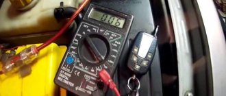
It happens that the incorrect functionality of the battery is obvious. A multimeter comes to the rescue here too. Having picked it up and set it up to measure current, you need to:
First we disconnect one terminal, then we connect the red contact to the positive value. Accordingly, black goes to minus. A normal voltage reading is considered to be between 12.4 and 12.8 V.
Remember! Measurements are taken no earlier than an hour after the engine is turned off.
You still need to measure the voltage under load. This means that it should be equal to a figure twice as large as the capacity.
This means that if the capacity is, say, seventy-five A/hour, the corresponding load should be one hundred and fifty amperes. A voltage drop below nine indicates a battery malfunction. This may also indicate that the battery is undercharged. When you disconnect the load, the voltage usually returns to normal within seven seconds.
By the way, it is better to carry out wiring diagnostics armed with a diagram of the electrical equipment of your car.
How to check a car battery with a multimeter
If you suspect that the battery is not working well, then again, a multimeter will help you. So, arm yourself with a multimeter configured to measure voltage (20V):
- Disconnect one terminal and connect the red contact to the positive and the black to the negative. Normal voltage should be between 12.4 - 12.8 Volts. It is important to take measurements at least an hour after stopping the engine.
- Measure the voltage under a load equal to twice the capacitance. For example, if the capacity is 75 Am/hour, then the load should be 150 Am. If the voltage drops below 9 Volts, it means something is wrong with your car’s battery (undercharging or failure). After disconnecting the load, the voltage should be restored within 5-10 seconds.
To repair home electrical wiring or a car's on-board network, you always need to know how to test wires with a multimeter. This device tests the integrity and serviceability of the cable; it can be used to check the insulation resistance and current voltage in the home electrical network. This is an indispensable meter for wiring and practical implementation of electrical projects.
How to test wires with a multimeter
The most convenient, understandable and safe way to diagnose wires for continuity or short circuit is to check with a multimeter. There are a large number of multifunctional devices with different parameters and prices: from the simplest and most affordable to the more expensive, accurate and functional. But with almost any multimeter you can check the integrity of the conductors; you don’t have to have expensive equipment for this.
What should the multimeter readings be?
There are two methods of checking using such a device: in resistance measurement mode and in continuity mode.
The dialing mode is the most convenient testing method. Here you do not need to have any knowledge of the instrument readings. It is enough to connect the probes of the device to the ends of the cable and hear the sound. In order, the procedure is as follows:
- Turn on the multimeter, set the dialing mode (an icon of several brackets of different sizes, similar to the Wi-Fi designation);
- Connect one probe to one end of the conductor being tested, the second probe to the other end of the same wire;
- If you hear a sound, it means the cable is intact. If there is no sound, there is a break in the line (or the probes are connected incorrectly).
It should be noted that in this way the presence of a short circuit in adjacent conductors is also checked. The only difference is that one probe is connected to the first conductor, and the second probe to the second: if there is sound, there is a short circuit.
The resistance measurement mode is somewhat more complicated. But if you remember what readings should be on the multimeter in different situations, it will be much easier. Moreover, many multimeters do not have a continuity mode, but there is almost always a resistance measurement mode.
The procedure for such a measurement will be as follows:
- Turn on the device, set the switch to resistance measurement mode, set the minimum value for measurement (usually 200 Ohms);
- Connect the probes to the conductor;
- If the display shows any value or zero, then the conductor is intact. If you see the number 1 on the screen, it means the resistance is infinite, that is, the cable is broken.
Reverse sequence for determining a short circuit between conductors or ground: with infinite resistance, the insulation between the conductors is not broken, and the presence of at least some resistance will mean a short circuit.
If you are confident in the integrity of the cable, then in this way you can identify the ends of the same conductor in a bundle of wires with the same color marking. It is enough to connect the probe to the conductor on one side, and on the other hand, alternately lean the probe against each conductor in the bundle. When the signal sounds, you have found the other end of the wire. That's all, nothing could be simpler.
Continuity of a long conductor
To test a wire whose ends are far away and there is no way to reach from the beginning to the end of the wire with two multimeter probes, you can use known wires or ground. For example, a cable may have a colored core, then all the white wires can be called out by connecting it to the white ones at one end and searching for this pair at the other.
If this is not possible, you can use grounding. We connect the wire core to the ground at one end, and at the other we look for a conductor sitting on the ground
It is important here that the grounding is reliable at both ends, otherwise it will not be possible to ring the wire in this way.
Setting up and preparing the multimeter
To use the multimeter correctly, you need to configure it. This means that you need to select the value to be measured and the limit of its operation, that is, the value beyond which it will not go.
Symbols on the front panel of the meter
A multimeter can be used to check various electrical quantities: current, voltage, resistance, frequency. It is also used to test the performance of various radio elements: resistors, capacitors, diodes and transistors. The very part of the word “multiple” implies the presence of several types of measurements. To select these types, there is a knob on the front panel of the tester, by turning which you can select the required value.
There is a higher class type of multimeter, for example, Agilent, in which the selection of measurement values is made not with a rotary knob, but with buttons. To select a value, simply click on the button corresponding to this value.
In most cases, the symbols depicted on the body of the multimeter represent designations of electrical quantities accepted in physics or conventional graphic designations of radioelements intended for testing . On the front panel you can find the following symbols:
- U - voltage symbol;
- V - stands for volts, this is also a measure of voltage;
- I is the current; when you set the knob to this designation, the current strength will be measured;
- A - amperes, a measure of current strength;
- Ω, R - symbol of resistance;
- Ohm is a measure of resistance, Ohms;
- -| |- - this icon indicates a capacitor, the multimeter will measure its capacitance;
- Diodes and transistors are also marked on the tester body with their symbols.
But not only the measured values are indicated on the front panel of the tester: the holes for connecting the probes also have their own designations. One of the meter slots will always be occupied by the black probe. This is a common hole, it is usually marked with the inscription COM, which means “common”. In addition to it, the multimeter has two or three working holes, designed respectively for measuring voltage, low current and high current.
The socket marked U, Ω, Hz is intended for measuring resistance, voltage and frequency, as well as for testing various radio elements. You also need to install a probe here to test wires and cables for breaks.
The hole marked mA (mA) is used to test low currents (up to 1 ampere), and the hole marked A (10 A) is needed to measure high amperages.
Also next to the voltage and current icons there are symbols
or -. This indicates the nature of the measured quantity: direct or alternating current or voltage.
Limits of measured values
In addition to designations of the values of the parameters being tested, designations of measurement limits are printed on the front panel of the multimeter. In more advanced equipment, these inscriptions are not present, since the tester electronics itself selects the limit based on the signal supplied to it at the input. However, most multimeters require manual adjustment of measurement limits.
Read also: Emery from the washing machine motor
Typically, limits are given by numbers that are multiples of 2: 2, 20, 200... Thus, when choosing a limit, you should be guided by the rule: choose a limit higher than the one being measured, but of the same order. For example, to measure the voltage in a home electrical network (in an outlet), you need to select the AC voltage measurement mode and the measurement limit of 2000 volts. And to test the wires with a multimeter, you need to select the resistance mode and the minimum measurement limit of 2 ohms. However, long cables require a higher measurement limit of 20 ohms. Additionally, you can turn on the button with a sound signal that sounds when a short circuit occurs (circuit presence).
Connecting the tester
To check the parameters of electrical circuits and the continuity of wires and cables with a multimeter, you must correctly connect the meter to the circuit being tested. When checking for circuit integrity, the required area between the meter leads is checked. Therefore, the tester is connected to the terminals of the circuit. If voltage is being measured, the multimeter must be connected in parallel to the section where the voltage is being tested.
When measuring current, the multimeter must be connected in series to the open circuit of the circuit being tested, for example, between the power supply terminal and the load terminal.
General information
You don't need to be a professional electrician to find a wire break. It is enough to have a measuring device - a multimeter . A multimeter is a multifunctional measuring instrument with its own voltage source. The device can measure the voltage in the circuit, the magnitude of the current and the resistance value. Many multimeters are used to test the continuity of a connection in a circuit.
If a connection is found, then if there is a built-in speaker, the device emits a sound signal. This is where the term “call” comes from. The device rings if there is a connection. A multimeter can also indicate that there is no connection between elements and helps determine a short circuit. Using the tester, all kinds of radio components are checked: resistors, transistors, diodes, relays, capacitors, and so on.
Conductor continuity is based on Ohm's law for a section of an electrical circuit. Ohm's law states that the resistance of an element is equal to the ratio of the applied voltage to the magnitude of the current in a section of the electrical network. Resistance is measured in Ohms. A resistance of one Ohm indicates that a current equal to one Ampere flows through the conductor at a given voltage of one Volt. Based on the calculated data on resistance, conclusions are drawn about the results of the call.
That is, a certain voltage is set on the multimeter, and the current value is determined using the instrument scale and the resistance is calculated. In other words, the multimeter is a voltage source and an ammeter to measure the resulting current.
Checking electrical circuit parameters
When testing electrical circuits, you can test many of their parameters. This includes current, network voltage, and signal frequency. But to determine serviceability, you only need to ring the circuit for integrity and check the insulation resistance. Both can be done with a multimeter.
In order to know how to test electrical wiring with a multimeter, you need to correctly configure the measuring device and correctly perform the measurement steps. To check the integrity of the wire you need:
- Connect the black probe of the multimeter to the socket labeled COM, and the red one to the socket labeled U, Ω, Hz;
- The meter knob must be set to the 20 Ohm position;
- Connect the measuring contacts to both ends of the wire. If the ends are in different places in the room, you need to use a previously tested extension wire;
- The tester screen will display the value. If the value does not exceed 2 ohms, it means that the integrity of the wire is not compromised. If the readings are not at the same level or more than 8-10 ohms, then there is a break in the circuit.
In the same way, wires in a car and cables of various electronic devices are tested.
In addition to checking integrity, wires are tested for insulation resistance. This can also be done with a multimeter:
- The probes remain in the same holes as when checking integrity;
- The measurement mode selected is the same - resistance test;
- The measurement limit must be selected as large as 20 or 200 megaohms;
- Touch the probes to opposite conductors of the cable: phase and neutral or phase and screen. In a car, this is ground and signal wire;
- The screen should remain displaying infinity; if there is any value instead, it means there is a short circuit somewhere. Changing values indicate interference in the network.
In addition to ordinary wires, there are high-voltage wires that can withstand high current and voltage loads. These include spark plug wires in cars. The current that is required when starting the engine flows through them; this current reaches 80-150 amperes. Knowing how to test high-voltage wires with a multimeter is required when diagnosing car electronics. The ringing of these wires occurs according to the indicated diagram , with the difference that it is necessary to set a larger resistance measurement limit. Typically this limit should be set at 20 kilo-ohms.
After this, you need to find the ends of the wire and connect the multimeter probes to them. The resistance of this wire will be displayed on the device screen. It should be in the range from 1 to 10 kOhm.
In trucks, as well as in networks located in places subject to constant mechanical stress, conductors with a screen - armor or armored wires - are placed. The only special feature of the armored wire is the screen, made of durable metal. You can check the integrity and insulation of the armored wire in the same way as a regular one, you only need to have access to its ends and the screen outlet.
Checking the wire for a break with a multimeter
Checking the integrity of the car wires must be carried out in compliance with electrical safety rules. Otherwise, the performer may receive electric shock. He must also understand the basic functioning of electrical equipment in order to perform the test correctly.
Important! If a car owner has doubts about his ability to work safely in electrical networks, then it is better to use the services of an electrician.
Therefore, for this test to be successful, you will need a multimeter, a wrench, and also a flashlight. Before performing the test, make sure that the power supply to the wire is turned off.
Setting up the multimeter
Before finding a short circuit in the car wiring, set up the multimeter correctly. It must be set to ohm range. The maximum limit of this multimeter measurement is open circuit (OL), because when there is an open circuit, the meter detects the resistance of the air gap between the two terminals. Some models may require the user to press the continuity button.
Resistance measurements are carried out using special probe wires: black is inserted into the COM connector, and red into the AV connector. Before starting work, make sure that the probes are correctly installed and secured.
Continuity testing
If there is no voltage at the fuse, and the fuse itself is working, then you will need to check the section of the circuit between the fuse holder connection and the battery. For example, there may be a poor connection to the battery in this part of the circuit.
When checking electrical or electronic components in a car, use a 10 megohm digital multimeter to prevent damage to the car's computer and other electrical devices.
Checking the circuit for open circuit:
- Select the circuit to be tested.
- Turn the ignition key to the “On” position and start the engine at idle speed.
- Connect the negative black lead of the meter to ground, and the positive red lead to the positive load side of the circuit under test.
- If the multimeter scale reads 0 V, move the red meter lead to the output side of the switch or relay control device. If 10.5 V now appears on the screen, then there is a gap between the load and the control device. If above 10.5 V, then move the red meter lead to the grounded side of the load.
- If the multimeter reads 1V or more but less than the battery voltage, there is too much resistance on the ground side of the circuit. This could be a corroded or loose connection, or a damaged wire that is preventing current from flowing properly.
- If the multimeter shows battery voltage, it means there is an open circuit on the ground side of the circuit.
Attention! In order to fix this, make sure that the grounding line is intact and not subject to corrosion. If necessary, install a jumper to create a reliable good grounding in order to determine the operability of the circuit with an intact grounding line.
Isolating the Problem Circuit
In order to check the integrity of a section of the circuit that raises doubts about its functionality, it is necessary to isolate this section from the rest of the circuit. Disconnect this part of the circuit by removing the connector, switch, or load from each end of the section to be tested.
Set the meter to continuity or to the lowest value on the ohm scale. Connect one of the DMM leads to one end of the isolated circuit and the other lead to the other end. If the display shows “OL” - infinite resistance, then there is an open in that part of the circuit.
Next you will need to move one of the terminals closer to the other and check the circuit resistance again or test it with a multimeter. Shorten the circuit gradually until the multimeter beeps.
Important! The gap will be located between this point and the previous point that was checked. If the DMM beeps or the display shows 0.3 ohms or similar small resistance value, there is no open circuit.
However, if the measurement results in a higher resistance, this indicates a weak or corroded connection, terminal or wire. If necessary, check the voltage drop in this part of the circuit to determine the cause of the failure.
Checking the spark plug circuit
Spark plug cables often fail due to extreme operating conditions: temperature changes, vibration, high electrical loads and the presence of chemicals such as oil, grease and coolant.
First check the spark plug wires for visual damage: melted or cracked insulation.
If there is no visible damage to the wires, then perform a resistance test with a digital multimeter on the Ω scale. Hold the meter probes at each end of the cable and read the total resistance on the scale.
How to find a short circuit in a car wiring with a multimeter
There are 2 types of short circuits in automotive wiring: to power and to ground. During a short circuit to ground, the current flows from the electrical circuit to the body. In this situation, the wires, in contact with the body or engine, heat up and lose their protective insulation characteristics. Fuses, lighting devices and sensors also fail.
A power short occurs in a harness with too many wires placed close together. Frayed or broken wires are connected to each other, forming an emergency circuit, and turn on equipment that is not currently needed. For example, when the headlights are turned on, a beep sounds. Finding a short circuit in a separate circuit is quite difficult. In order to simplify diagnostics, modern cars use color-coded electrical wiring diagrams (EWD).
To check the short circuit, it is recommended to take safety measures and carry out work using safety glasses. Next, we find the car battery by disconnecting the positive cable from the battery and placing it so that its end does not touch the equipment or cables.
They identify a non-working device, disconnect its power wires, having previously established their polarity and position them so that they do not touch anything.
The positive wire to the fuse box is disconnected from the panel so that its end is free. The negative wire from the ground strip is also disconnected in the same way. The ohmmeter probes are connected to the positive and negative wires, respectively, and the readings of a digital multimeter or analog are monitored along the arrow. If the arrow initially tilts to the side and then returns to its original position, then there is no short circuit in the circuit. If the arrow deviates and remains in place, there is a short circuit in the circuit.
Obviously, it is quite difficult to detect this type of fault with a conventional multimeter. To do this, it is better to use a special CMS test controller for the wiring harness, which allows you to determine whether the wire is live thanks to the built-in sensor.
Measuring range from 0 to 60V DC, can also measure AC current. This does not require the user to damage the wire sheath to get to the conductive metal. The detector allows you to quickly identify wires with poor contact or poor conductivity due to insulation failures, or other failures in structural integrity.
The results will be read on the LCD screen, and the measuring sensor can penetrate even the most inaccessible places, so there is no need to disassemble the car.
Modern cars have more than 1,500 wires for various purposes. They work in difficult conditions: at high temperatures, increased vibration and chemically active environments. Therefore, it is not surprising that some wires often break or lose the integrity of their insulating cover. In this case, the driver will need to independently determine the location of the short circuit in the circuit using a multimeter.
Safety requirements
When performing any inspections of live electrical networks, safety requirements must be followed. You cannot work without protective insulated shoes, and it is also better to wear rubber gloves. When checking the integrity and insulation resistance of electrical circuits, it is necessary to de-energize the network by turning off the circuit breakers, so all checks should be carried out during daylight hours, since with emergency lighting and the light of lanterns you can only work in case of an emergency.