Electric circuits and their varieties
An electrical circuit is a complex of devices and individual objects that are connected in a given way. They provide a path for electrical current to pass. To characterize the ratio of the charge flowing within each individual conductor over a period of time to the duration of this time, a certain physical quantity is used. And this is the current strength in an electrical circuit.
Such a circuit includes an energy source, energy consumers, i.e. load and wires. They are divided into two types:
- Unbranched - the current moving from the generator to the energy consumer does not change in value. For example, this is lighting that includes only one light bulb.
- Branched - chains that have some branches. The current, moving from the source, is divided and goes to the load along several branches. At the same time, its meaning changes.
An example would be lighting that includes a multi-arm chandelier.
A branch is one or more components connected in series. The current flows from the node with high voltage to the node with its minimum value. In this case, the incoming current at the node coincides with the outgoing one.
Circuits can be nonlinear and linear. If in the former there are one or more elements where there is a dependence of the values on current and voltage, then in the latter the characteristics of the elements do not have such a dependence. In addition, in circuits characterized by direct current, its direction does not change, but under the condition of alternating current, it changes taking into account the time parameter.
Problems using Kirchhoff's rule with solutions
How to solve problems using Kirchhoff's rule? Before you start solving problems, be sure to study the theory. We have also prepared for you a universal guide to solving physical problems.
Problem No. 1 on equivalent transformations of conductor connections.
Condition
Transform the circuit using equivalent transformations.
Solution
In addition to the basic formulas for connecting conductors in series and parallel, there are formulas for converting a resistor star into an equivalent triangle and vice versa. The triangle of resistors R2 R3 R4 can be converted into an equivalent star RB RB RD using the formulas:
The converted circuit will look like this:
Answer: see above.
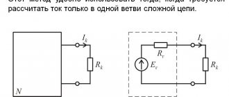
Kirchhoff's rules apply to complex circuits (for example, circuits with multiple power supplies) when equivalent transformations do not produce results.
Problem No. 2 on the first rule (law) of Kirchhoff
Condition
It is necessary to compose equations according to Kirchhoff’s first law for the following chain:
Solution
There are 4 nodes in this chain. According to the first law, we compose 3 equations (1 equation less than the number of nodes):
Answer: see above.
To solve problems using Kirchhoff's rules, you must be able to solve systems of linear equations. To solve complex systems, it is convenient to use special programs: MathCad, MatLab, etc.
Next, for clarity, we will consider a problem with a simpler scheme.
Problem No. 3 using Kirchhoff's rules
Condition
Two power supplies E1=2V and E2=1V are connected according to the circuit shown in the figure. Resistance R=5 Ohm. The internal resistance of the sources is the same and equal to r1=r2=1 Ohm. Determine the current that passes through the resistance.
Solution
According to Kirchhoff’s first law, the sum of currents converging at a node is equal to zero (we denote the currents arbitrarily):
Let's choose the direction of traversing the upper contour counterclockwise. According to Kirchhoff's second law, the sum of the voltage drops in the circuit is equal to the sum of the emf:
Let's write the same for the second circuit, going around it clockwise:
Let's combine equations with unknown currents into a system:
To solve the system, we express the current strength I1 from the second equation, and the current strength I2 from the third:
The first equation can now be written as:
Expressing the desired current and substituting the values from the condition, we obtain:
Answer: 1.5 A.
Problem No. 4 using Kirchhoff's rules
Condition
A diagram of the electrical circuit is given. Necessary:
- indicate the resistance, above each branch indicate its current and sources of emf;
- indicate on the diagram the directions of currents and EMF;
- draw up equations using Kirchhoff's first and second laws.
Solution
Let us present the diagram, indicating resistance, EMF and currents:
There are 7 currents and 4 nodes in the circuit. It is necessary to compose 4 – 1 = 3 equations according to Kirchhoff’s first law and 7 – 3 = 4 equations according to Kirchhoff’s second law.
Kirchhoff's first law:
Kirchhoff's second law (selected contours K1, K2, K3, K4 are shown in the figure):
Answer: see above.
Problem No. 5 using Kirchnoff's rules
Condition
Determine all currents in the branches by creating a system of equations according to Kirchhoff’s laws.
Circuit parameters: E1 = 40 V, E2 = 50 V, E3 = 60 V, R01 = 0.1 Ohm, R02 = 0.3 Ohm, R03 = 0.2 Ohm, R1 = 4.4 Ohm, R2 = 4, 7 ohms, R3 = 4.6 ohms, R4 = 5.2 ohms, R5 = 7.6 ohms.
Solution
The directions of currents in the branches of the circuit and the directions of bypassing the circuits are indicated in the diagram. The chain contains 3 nodes and 3 independent circuits. Thus, to calculate the currents in the branches, it is necessary to compose two equations according to the first Kirchhoff law and three according to the second:
Let's substitute the numerical values and solve the system of equations:
Answer: I1=10.68 A; I2=8.388 A; I3=7.192 A; I4=4.9 A; I5=2.292 A.
Current strength and Ohm's law
When calculating the current strength of a circuit, it should be remembered that this quantity is of a physical type, demonstrating a certain charge. It flows for a certain time unit along the conductor. The basic calculation scheme is as follows:
I=q/t , where:
- I is the power of electricity in Amperes (A) or C/s;
- q – charge moving within the conductor in Coulombs (C);
- t – time spent moving the charge, s.
In accordance with the provisions of Ohm's law, for a separate part of the circuit, when calculating the current strength, a diagram is used showing:
- direct dependence of current on voltage;
- inverse relationship with resistance.
I=U/R , where:
- U – voltage expressed in volts, V;
- R – resistance indicator, Ohm.
From here the following dependence will follow:
I = E/ R+r , where:
- E – emf, V;
- R – external type resistance, Ohm
- r – internal resistance, Ohm
Use other online calculators:
Calculation of DC electrical circuits using the method of equivalent transformations
Home → Examples of solving TOE problems → Calculation of DC electrical circuits by the method of equivalent transformations Calculation of DC electrical circuits by the method of equivalent transformations
The basic laws that determine the calculation of an electrical circuit are Kirchhoff's laws.
Based on Kirchhoff's laws, a number of practical methods for calculating DC electrical circuits have been developed, allowing to reduce calculations when calculating complex circuits.
It is possible to significantly simplify calculations, and in some cases reduce the complexity of calculations, using equivalent circuit transformations.
Converts parallel and series connections of elements, a star connection into an equivalent delta connection and vice versa. The current source is replaced with an equivalent EMF source. Using the method of equivalent transformations, it is theoretically possible to calculate any circuit, and at the same time use simple computing tools. Or determine the current in any one branch, without calculating the currents of other sections of the circuit.
This article on the theoretical foundations of electrical engineering examines examples of the calculation of linear DC electrical circuits using the method of equivalent transformations of typical circuits for connecting energy sources and consumers, and provides calculation formulas.
Problem solving Calculation of DC electrical circuits by the method of equivalent transformations
Task 1. For the circuit (Fig. 1), determine the equivalent resistance relative to the input terminals a−g, if known: R1 = R2 = 0.5 Ohm, R3 = 8 Ohm, R4 = R5 = 1 Ohm, R6 = 12 Ohm, R7 = 15 Ohm, R8 = 2 Ohm, R9 = 10 Ohm, R10 = 20 Ohm.
Rice. 1
Solution
Let's start the equivalent transformations of the circuit from the branch furthest from the source, i.e. from terminals a−g:
Task 2. For the circuit (Fig. 2, a), determine the input resistance if it is known: R1 = R2 = R3 = R4 = 40 Ohm.
Rice. 2
Solution
The original circuit can be redrawn relative to the input terminals (Fig. 2, b), from which it can be seen that all resistances are connected in parallel. Since the resistance values are equal, to determine the equivalent resistance value, you can use the formula:
where R is the resistance value, Ohm;
n – number of parallel connected resistances.
Task 3. Determine the equivalent resistance relative to terminals a–b, if R1 = R2 = R3 = R4 = R5 = R6 = 10 Ohm (Fig. 3, a).
Rice. 3
Solution
Let us transform the delta connection f−d−c into the equivalent star connection. We determine the values of the converted resistances (Fig. 3, b):
According to the conditions of the problem, the values of all resistances are equal, which means:
In the transformed circuit, we obtained a parallel connection of branches between nodes e–b, then the equivalent resistance is equal to:
And then the equivalent resistance of the original circuit is a series connection of resistances:
Task 4. In a given circuit (Fig. 4, a) determine the input resistances of branches a−b, c–d and f−b using the method of equivalent transformations, if it is known that: R1 = 4 Ohm, R2 = 8 Ohm, R3 =4 Ohm, R4 = 8 Ohm, R5 = 2 Ohm, R6 = 8 Ohm, R7 = 6 Ohm, R8 =8 Ohm.
Solution
To determine the input resistance of the branches, all sources of EMF are excluded from the circuit. In this case, points c and d, as well as b and f, are short-circuited, because The internal resistance of ideal voltage sources is zero.
Rice. 4
Branch a−b is broken, and since resistance Ra–b = 0, then the input resistance of the branch is equal to the equivalent resistance of the circuit relative to points a and b (Fig. 4, b):
Similarly, the input resistances of the branches Rcd and Rbf are determined by the method of equivalent transformations. Moreover, when calculating resistances, it is taken into account that short-circuiting points a and b excludes (“short-circuits”) resistances R1, R2, R3, R4 from the circuit in the first case, and R5, R6, R7, R8 in the second case.
Task 5. In the circuit (Fig. 5) currents I1, I2, I3 using equivalent transformations draw up a power balance , if known: R1 = 12 Ohm, R2 = 20 Ohm, R3 = 30 Ohm, U = 120 V.
Rice. 5
Solution
Equivalent resistance for parallel connected resistances:
Equivalent resistance of the entire circuit:
Current in the unbranched part of the circuit:
Voltage across parallel resistances:
Currents in parallel branches:
Power balance:
Task 6. In the circuit (Fig. 6, a), determine the ammeter readings using the method of equivalent transformations , if it is known: R1 = 2 Ohm, R2 = 20 Ohm, R3 = 30 Ohm, R4 = 40 Ohm, R5 = 10 Ohm, R6 = 20 Ohm, E = 48 V. The resistance of the ammeter can be considered zero.
Rice. 6
Solution
If resistances R2, R3, R4, R5 are replaced by one equivalent resistance RE, then the original circuit can be represented in a simplified form (Fig. 6, b).
Equivalent resistance value:
By transforming the parallel connection of resistances RE and R6 of the circuit (Fig. 6, b), we obtain a closed circuit for which, according to Kirchhoff’s second law, we can write the equation:
where does the current I1 come from:
We express the voltage at the terminals of parallel branches Uab from the equation according to Ohm’s law for the passive branch obtained by transforming RE and R6:
Then the ammeter will show the current:
Task 7. Determine the currents of the circuit branches by the method of equivalent transformations (Fig. 7, a), if R1 = R2 = R3 = R4 = 3 Ohm, J = 5 A, R5 = 5 Ohm.
Rice. 7
Solution
Let us transform the “triangle” of resistances R1, R2, R3 into an equivalent “star” R6, R7, R8 (Fig. 7, b) and determine the values of the resulting resistances:
Let's transform the parallel connection of branches between nodes 4 and 5
The current in the circuit obtained as a result of the transformations is considered equal to the current of the current source J, and then the voltage:
And now you can determine the currents I4 and I5:
Returning to the original circuit, we determine the voltage U32 from the equation according to Kirchhoff’s second law:
Then the current in the branch with resistance R3 will be determined:
The values of the remaining unknown currents can be determined from the equations according to Kirchhoff’s first law for nodes 3 and 1:
Electronic version of the article Calculation of DC electrical circuits by the method of equivalent transformations
Examples of problem solving Calculation of DC electrical circuits by the method of equivalent transformations
Calculation of DC electrical circuits using the method of equivalent transformations
Equivalent transformation method
09/02/2011, 303993 views.
Add a comment
Educational materials
According to Kirchhoff's first law, the algebraic sum of the currents of the branches converging at a node is equal to zero:
According to Kirchhoff's second law, the algebraic sum of the voltages on the resistive elements of a closed circuit is equal to the algebraic sum of the emfs included in this circuit.
Get a decision on TOE
The calculation of a multi-circuit linear electrical circuit having “b” branches with active and passive elements and “y” nodes comes down to determining the currents of individual branches and voltages at the terminals of the elements included in this circuit.
A branch that does not contain an EMF source is called passive. The branch containing the EMF source is called active.
Kirchhoff's 1st law applies to independent nodes, i.e. those that differ from each other in at least one new branch, which allows us to obtain (y - I) equations.
The missing equations in the amount of b - (y - I) are composed based on Kirchhoff's second law. The equation is written for independent circuits that differ from one another in at least one branch.
Calculation procedure:
- identify branches, independent nodes and circuits in an electrical circuit;
- using arrows, they indicate arbitrarily chosen positive directions of currents in individual branches, and also indicate an arbitrarily chosen direction of bypassing the circuit;
- make up equations according to Kirchhoff’s laws, applying the following sign rule:
- currents directed to a circuit node are written with a “plus” sign, and currents directed from the node are recorded with a “minus” sign (for Kirchhoff’s first law);
- The EMF and voltage on the resistive element (RI) are taken with a plus sign if the directions of the EMF and current in the branch coincide with the direction of bypassing the circuit, and if in the opposite direction - with a minus sign;
Negative current values of any branch indicate that the previously selected arbitrary current directions turned out to be erroneous. This should be taken into account, for example, when constructing a potential diagram, where the true direction of the current must be known.
In Fig. 4, a shows the original electrical circuit, for which the currents in the branches should be calculated. The directions of currents and circuit bypass are shown in Fig. 4, b.
Fig.4
The system of equations compiled according to Kirchhoff’s first and second laws has the form
Next >Lectures on the basics of electrical engineering >
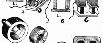
Series connection of elements
Total resistance
Such inclusion implies a combination of parts in direct sequence. The output of one resistance is connected to the input of another. In this case, there are no branches on the site. The amount of current that passes through all components connected in series will be the same.
Attention! The reduction in potential across each resistive element adds up to the total voltage applied to the series circuit.
Series connection of resistors
In the case of direct current, the formula for Ohm's law for a circuit segment has the form:
I = U/R.
The strength of the current depends on the applied voltage and the resistance provided to it. If we express R , its formula is:
R = U/I.
The parameters of a sequential circuit, including n elements connected to each other, have their own characteristics.
The current passing through the circuit is the same everywhere:
I = I1= I2= … = In.
The applied voltage is the sum of the voltages across each resistor:
U = U1 + U2+ … + Un.
Therefore, we can calculate the total:
Req.= U1/I + U2/I + … +Un/I) = R1 + R2 + … +Rn.
Important! A series circuit containing N resistors of equal value has an equivalent resistance Req. = N*R.
Calculation for mixed connection of devices
Resistor resistance - formula for calculation
It is simply impossible to calculate the resistance of a circuit when it is branched and filled with different types of resistive connections. The solution to the problem is complicated by the many areas where parts are connected to each other in different combinations. In such circumstances, it is desirable to perform a series of transformations, achieving simplification of the circuit by introducing individual equivalent elements. In this case, suitable circuits for serial and parallel connections are identified.
For example, having found a certain number of serial connections of resistors, replace them with one equivalent component. Having determined the elements connected in series, they also draw an equivalent instead. The search for such simple connections is beginning again.
The method is called the "coagulation method". The circuit is simplified until there is only one Req left in it.
Calculation method for mixed connection
Important! The method of equivalent transformations is used when the power supply to the section of the circuit under consideration is carried out from a single source of electric current, as well as when determining Req. in a closed loop with one EMF.
This relative method of determining Req is also used to study the dependence of currents in a certain circuit on the load R value. This is the equivalent generator method, in which a complex two-terminal network, which is active, is represented as an equivalent generator. In this case, it is believed that its EMF corresponds to Uх.х. (idle circuit) on the terminals, R internal corresponds to R input of the passive two-terminal network on the same terminals. For this determination, the current sources are disconnected and the EMF channel is short-circuited.
Parallel connection
Current resistance: formula
When the conditional outputs of the parts have a common contact at one point (node) of the circuit, and the conditional inputs are also combined at the second, they speak of a parallel connection. A node in the drawing is indicated by a graphic dot. This is the place where branching circuits occur in circuits. This option for connecting resistors ensures the same voltage drop U for all parallel elements. The current in this position will be equal to the sum of the currents flowing through each component.
n are included in a parallel connection , the potential difference, current and total resistance will have the following expressions:
- total current: I = I1 + I2 + … + In;
- total voltage: U = U1 = U2 = … = Un;
- Rtot. = Req. = U/I1 + U/I2 + …+ U/In) = 1/R1 + 1/R2 +…+ 1/Rn.
The quantity inversely proportional to resistance 1/R is called conductivity.
If n resistances of equal nominal value are connected in parallel, then Req. = (R*R)/n*R = R/n. The formula is also suitable for the inductive reactance of wire coils and the capacitive reactance of capacitors.
Parallel connection of resistors