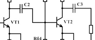
The home craftsman will be interested in 3 types of diagrams: functional, schematic, installation.
KU - control button. D - Grounding symbol.
In order to read any text, you need to know the alphabet and reading rules. The switch can be designated using the letter code Q without the automatic shutdown feature F. How to read electrical diagrams. Radio components marking designation Symbols reflect only the main function of the contact - closing and opening the circuit.
To depict the switching devices included in the electrical system, 4 main symbols are used. Single-line electrical circuits also have their own letters, which make it clear what is included in the network.
The number of segments is the number of sockets on one body (illustration in the photo below).
The number of taps displays the number of keys on this device. A characteristic feature of this scheme is minimal detail.
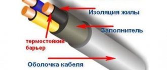
Cables with the number of cores Switches and sockets with open and hidden installation methods have their own symbols on the GOST drawings.
Drawing a hydraulic diagram [2] in CAD Compass3D
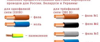
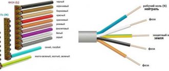
Wire color coding
Anyone who has ever dealt with wires and electricity has noticed that conductors always have different insulation colors. This was done for a reason. The colors of the wires in electrics are designed to make it easier to recognize the phase, neutral wire and ground. They all have a certain color and are easily distinguished during operation. The color of the phase, neutral, and ground wires will be discussed further.
How phase wires are painted
When working with wiring, phase wires pose the greatest danger. Touching the phase, under certain circumstances, can become lethal, which is probably why bright colors were chosen for them. In general, the colors of electrical wires allow you to quickly determine which of a bunch of wires are the most dangerous and work with them very carefully.
Coloring of phase wires
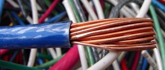
Most often, phase conductors are red or black, but other colors are also found: brown, lilac, orange, pink, purple, white, gray. Phases can be painted in all these colors. It will be easier to deal with them if you exclude the neutral wire and ground.
In the diagrams, phase wires are designated by the Latin (English) letter L. If there are several phases, a numerical designation is added to the letter: L1, L2, L3 for a three-phase 380 V network. In another version, the first phase is designated by the letter A, the second by B, and the third by C .
Ground wire color
By modern standards, the ground conductor is yellow-green. It usually looks like yellow insulation with one or two longitudinal bright green stripes. But there are also transverse yellow-green stripes in color.
Grounding may be this color
In some cases, the cable may only have yellow or bright green conductors. In this case, the “earth” has exactly this color. It is displayed in the same colors on diagrams - most often bright green, but it can also be yellow. Signed on diagrams or on ground equipment in Latin (English) letters PE . The contacts to which the “ground” wire must be connected are also marked.
Sometimes professionals call the grounding wire “neutral protective”, but do not be confused. This is an earthen one, and it is protective because it reduces the risk of electric shock.
What color is the neutral wire?
Zero or neutral is blue or light blue, sometimes blue with a white stripe. Other colors are not used in electrical engineering to indicate zero. It will be like this in any cable: three-core, five-core or with a large number of conductors.
What color is the neutral wire? Blue or cyan
“Zero” is usually drawn in blue on diagrams and signed with the Latin letter N. Experts call it a working zero, since, unlike grounding, it participates in the formation of the power supply circuit. When reading a diagram, it is often defined as "minus", while the phase is considered "plus".
How to check the correctness of marking and wiring
Wire colors in electrical engineering are designed to speed up the identification of conductors, but relying only on colors is dangerous - they could be connected incorrectly. Therefore, before starting work, you should make sure that you have correctly identified their affiliation.
Take a multimeter and/or an indicator screwdriver. It’s easy to work with a screwdriver: when you touch a phase, the LED built into the housing lights up. So it will be easy to identify phase conductors. If the cable is two-wire, there are no problems - the second conductor is zero. But if the wire is three-wire, you will need a multimeter or tester - with their help we will determine which of the remaining two is phase and which is zero.
Determining the phase wire using an indicator screwdriver
We set the switch on the device so that the selected jackal is more than 220 V. Then we take two probes, hold them by the plastic handles, carefully touch the metal rod of one probe to the found phase wire, the second to the supposed zero. The screen should display 220 V or the current voltage. In fact, it may be significantly lower - this is our reality.
If 220 V or a little more is displayed, this is zero, and the other wire is presumably “ground”. If the value is less, we continue checking. With one probe we again touch the phase, with the second - to the intended grounding. If the instrument readings are lower than during the first measurement, there is “ground” in front of you and it should be green. If the readings turn out to be higher, it means that somewhere there was a mistake with “zero” in front of you. In such a situation, there are two options: look for exactly where the wires were connected incorrectly (preferable) or simply move on, remembering or noting the existing position.
So, remember that when testing a phase-zero pair, the multimeter readings are always higher than when testing a phase-ground pair.
And, in conclusion, let me give you some advice: when laying wiring and connecting wires, always connect conductors of the same color, do not confuse them. This can lead to disastrous results - at best, equipment failure, but there may also be injuries and fires.
Copying/duplicating wire numbers on the diagram
In some cases, it is necessary to duplicate the wire number in different sections of the circuit. This situation, for example, arises when one circuit of a project is located on different sheets, or when it is necessary to emphasize the relationship of a particular wire to a given circuit.
- To start the procedure, click the Copy wire numbers Schematic tab Edit wires/wire numbers panel .
- Left-click on the wire in the place where you would like to set the additional number.
An additional wire number can only be placed if a number has already been assigned to this wire/circuit.
The additional number is placed in a layer for copies of wire numbers.
Designation L and N in electrics
Every time you try to connect a chandelier or sconce, a light or motion sensor, a hob or exhaust fan, a heated floor thermostat or an LED strip power supply, as well as any other electrical equipment, you can see the following markings near the connection terminals - L and N.
Let's figure out what the designations L and N mean in electrical engineering.
As you probably guessed, these are not just arbitrary symbols, each of them carries a specific meaning and serves as a hint for correctly connecting the electrical appliance to the network.
Standard wire pinout by color
When assembling the electrical panel
When assembling an electrical panel for a 380-volt three-phase network, the following color indication of cable cores is accepted as standard:
- Red or brown – phase A.
- Black – phase B.
- Gray, white – phase C.
- Blue – zero core.
- Yellow-green – “earth”.
Standard color indication of cable cores:
Meter box: requirements for a metal case for outdoor installation of a meter
D.C
If you are going to install an electrical network with direct current, then it should be said that the color pinout of the wires differs from the previous type and has its own characteristics. In particular, the main feature is the absence of a neutral core (the current flows in one direction, from + to –). This suggests that there will no longer be confusion with the blue color “phase or zero”. In DC networks, polarity is indicated as follows:
- The positive pole is the vein in the red braid.
- Negative - in blue or black insulation.
Electrical circuits with several ratings
Because for devices using electrical circuits with several ratings, there is no standard color designation. Therefore, you can figure out which wire is positive and which is negative by opening the accompanying technical documentation. Permanent circuits with bipolar pinouts have a blue zero color.
Automotive wiring
In automotive wiring, red, orange, or pink are the standard colors to indicate the positive wire. The ground in the on-board network is always a black-braided wire. The colors of the remaining wires can vary over a very wide range, and depend on the specific car manufacturer.
Designation L in electrical
“ L ” - This marking came to electrical engineering from the English language, and it is formed from the first letter of the word “Line” (line) - the generally accepted name for a phase wire. Also, if it is more convenient for you, you can focus on such concepts of English words as Lead (lead wire, core) or Live (under voltage).
Accordingly, the designation L marks the clamps and contact connections intended for connecting the phase wire. In a three-phase network, alphanumeric identification (marking) of phase conductors “L1”, “L2” and “L3”.
According to modern standards (GOST R 50462-2009 (IEC 60446:2007)) in force in Russia, the colors of phase wires are brown or black. But often, white, pink, gray or a wire of any other color except blue, white-blue can be found , blue, white-blue or yellow-green.
Inserting wire numbers on a diagram
- Wire numbering dialog box by clicking the corresponding Wire numbers on the Diagram in the Insert wires/wire numbers . In the window that opens, specify the required numbering parameters.
- Select the numbering option: within the project, within the drawing, or by indicating individual wires by clicking the appropriate button. Depending on the option chosen, the further procedure will differ.
With the option Within the drawing , wire numbers will be automatically assigned and marked on the current drawing.
If you select the option Within the project , you will need to make the necessary numbering settings in the following window:
After clicking OK, a standard dialog for selecting files for processing will open, in which you will need to select project files that require the assignment and arrangement of wire numbers.
Well, for the option with indicating individual wires, it will be necessary to indicate the wires that are subject to numbering.
Designation N in electrical
“N” is a marking formed from the first letter of the word Neutral (neutral) - the generally accepted name for the neutral working conductor, in Russia more often called simply the neutral conductor or briefly Zero (Zero). In this regard, the English word NULL (zero) is well suited, you can focus on it.
the designation N marks clamps and contact connections for connecting the neutral working conductor/neutral wire. Moreover, this rule applies to both single-phase and three-phase networks.
The colors of the wire that mark the neutral wire (zero, zero, zero working conductor) are strictly blue (light blue) or white-blue (white-blue).
Adding wire numbers and wire number callouts
AutoCAD Electrical allows you to automatically add wire numbers for each circuit in your design. Callouts can also be automatically added, both for each wire number, and only for those numbers for which there is not enough space to be placed without a callout.
Circuits are processed from left to right and from top to bottom. By default, the numbers are centered on the first chain segment found. But the user can specify an offset from the left end (for wires running horizontally) or from the top end (for wires running vertically).
By default, only one wire number is placed for each circuit. If necessary, the user can add as many copies of the wire number as he wants in different parts of the circuit.
If there are too many graphics in the default number locations, a wire number callout is added (unless callouts are not disabled).
Grounding Designation
If we are talking about the designations L and N in electrical engineering, we cannot help but note this sign - , which can also almost always be seen together with these two markings. This icon marks clamps, terminals or contact connections for connecting a protective grounding wire ( PE - Protective Earthing), also known as a neutral protective conductor, grounding, earth.
Unfortunately, often the electrical wiring in our apartments and houses is not carried out in compliance with all strict standards and rules for color and alphanumeric markings for electricians. And knowing the purpose of the L and N markings on electrical equipment is sometimes not enough for proper connection. Therefore, be sure to read our article “How to determine phase, zero and grounding yourself, using improvised means?” If you have any doubts, this material will come in handy.
Pinout of wires by color: terminology
So, let's understand the meaning of the terms: phase and neutral and zero. The power system has a 3-phase structure, the voltage between any pair of phases is 380 V. To reduce the voltage to the standard 220 V, a 0 wire was created in residential installations. The phase voltage between the neutral core and the 380 V wire will be equal to the potential difference with the familiar number 220 V.
Color range of current-carrying conductors according to the PUE:
- red;
- brown;
- black;
- gray;
- white;
- pink;
- orange;
- turquoise;
- purple.
European color marking standard
This contains many wire colors, except for those few elements that are intended exclusively to designate neutral and protective wires:
- blue color and its shades - working neutral wire (neutral - N);
- yellow with a green stripe - protective earth (PE);
- yellow-green insulation with blue marks at the ends of the conductors - combined (PEN) conductor.
It is allowed to use conductors with green insulation with a yellow stripe for grounding, and for combined conductors blue insulation with yellow-green marks at the ends.
Welding with an inverter for beginners: how to learn how to make the correct weld, welding equipment
What should a grounding sign look like?
As is known, a correctly executed connection between the housing of electrical equipment and the ground loop directly affects the safety of its operation. Grounding radio and electronic equipment is often an important factor in its proper operation. That is why the symbol denoting grounding is probably the most common sign in electrical engineering and electronics. It is found on equipment housings, special grounding buses in production shops and electrical substations; it can often be found on radio-electronic circuits, as well as communication circuits.
Grounding symbol applied to the housing of electrical equipment
The main purpose of the grounding sign is to inform about the point of connection of the equipment with the “ground”, that is, the grounding circuit. As a rule, the grounding symbol is applied near the stud to which the grounding bus or grounding conductor is directly screwed. It can also be applied near a special terminal or on the terminal itself. The dimensions of this symbol are proportional to the dimensions of the device, that is, it must be easily visible on the equipment and clearly indicate the grounding point.
Methods of applying a mark to equipment
It is generally accepted that all places where equipment is connected to the grounding circuit must have a symbol specified by GOST. In most cases, the mark is applied to the equipment at the manufacturer's factory and has a raised surface. Signs applied at the factory can have either a convex or depressed structure. More often, such signs are cast together with the metal or plastic body of the equipment, less often they are pressed out.
With any of these options, the signs are subject to additional coloring in order to stand out more clearly on the body. Nowadays it is popular to stick a grounding sign using special adhesive compounds or adhesive tape; this is a fairly simple method. The use of adhesive grounding symbols does not contradict GOST, and can be done after transportation; moreover, such signs are easy to update and replace.
State Standard 21130-75 clearly stipulates the parameters of the grounding symbol applied to metal or plastic enclosures using the casting method.
Dimensions of the grounding sign made by casting
A detailed description of the sizes is given in the table.
Typical dimensions for the above sign
This method of marking has gained wide popularity since the end of the 19th century and is actively used on modern equipment with both large and small dimensions. The connection sign with the grounding loop, made by stamping non-ferrous or ferrous metal, should look similar. This method is convenient for the manufacturer; the badge is applied during the manufacturing process of the case, which avoids additional manipulations.
Applying the grounding symbol by impact to the body of electrical equipment is often also carried out at the manufacturer, but it is also possible to use it directly at the installation site of the product.
More often, marking is applied using the impact method on small-sized equipment, the housings of which are made of ferrous or non-ferrous metal.
The requirements of GOST 21130-75 for “impact” grounding symbols are somewhat different than for signs made by casting. The main dimensions of such signs are shown in the figure below.
The sign of joining the “ground”, performed by impact
Typical dimensions for the above sign
Dimensions in the Tables are given in millimeters.
In both cases, the circle around the grounding sign, having a diameter D, is painted in a color different from the main color of the product, as a rule, it is yellow or black.
Currently, to indicate the connection points with the protective grounding loop, the corresponding sign can be applied by gluing. This is either imprinting the symbol on adhesive paper, or applying the symbol to laminated cardboard and then gluing it to the equipment.
Mark printed on adhesive base
The dimensions of such a badge must also comply with GOST and be proportional to the equipment. The use of this type of signs has a number of advantages, the main of which is the ease of application and ease of updating worn signs, even in hard-to-reach places and on products with small dimensions. The technology for manufacturing adhesive-based grounding symbols involves the use of high-quality adhesives and laminitis, which allows them to be used on equipment exposed to vibration and moisture.
Grounding signs on diagrams
On electrical diagrams, the application of the grounding symbol is also stipulated by the State Standard. In this case, they use GOST 2.721-74 and the Unified System of Design Documentation. Unlike the symbol on the chassis, the grounding symbols on the diagrams may differ.
There are three main grounding symbols and a sign for connecting the terminals to the equipment body.
Representation of grounding on electrical diagrams
In the first case, shown in the figure, a general graphic designation is presented for connecting a section of the circuit to ground. This sign is quite common in radio-electronic circuits, and is also often used to indicate working or measuring grounding on electrical circuits. In earlier versions, GOST provided only such a grounding designation, so on old diagrams it can also be found as a protective or silent connection of live parts to the “ground”.
The second example shows a silent grounding sign. Despite the fact that this type of grounding is quite rare, GOST 2.721-74 has provided a separate designation for it. An image of such a sign is required when, among the many equipment connected to common grounding lines, there is a device that requires a separate connection to its own grounding circuit. Sometimes it happens that the same device requires the connection of measuring, protective, working and silent grounding; in such cases, all three variants of symbols can be found on the diagram.
The third option is an image of protective grounding. Since the Safety Rules require the connection of all current-carrying parts of electrical equipment that are normally without voltage to “ground” - this sign is the most common on power electrical circuits. In its design, it is similar to the sign applied to equipment housings, and is also inscribed in a circle.
In addition to the above signs, in electronics there is often a connection between the current-carrying part and the equipment body. This type of connection is indicated by the fourth option of icons. It is important to note that a connection to the housing cannot be considered a full grounding, even if the equipment housing is subsequently connected to the ground loop.
The sizes of icons applied to the diagram must correspond to the ESKD and be proportional to the sizes of other elements of the diagram.
Video. Proper grounding
Knowledge of GOST 21130-75 allows you to correctly determine all grounding points on electrical equipment and periodically update the markings, which guarantees the safe and correct operation of devices. Without knowledge of the requirements of GOST 2.721-74, it is almost impossible to read or draw an electrical circuit. By correctly understanding the markings, you can immediately understand the specifics and operating principle of any electrical or electronic equipment.
Foreign pinout of wires by color
The main colors for marking abroad are as follows:
- neutral - white, gray or black;
- protective grounding - yellow or green.
- Standards in a number of countries allow the use of bare metal without insulation as protective grounding.
Grounding wires are switched on prefabricated non-insulated terminals and connect to each other all metal parts of the structure that do not have reliable electrical contact with each other. When assembling the electrical panel
Conventional graphic symbols in electrical circuits
Download free GOST
- GOST 21.614 Symbolic graphic images of electrical equipment and wiring in the original
- GOST 2.722-68 Conventional graphic symbols in diagrams. Electrical machines
- GOST 2.723-68 Conventional graphic symbols in diagrams. Inductors, reactors, chokes, transformers, autotransformers and magnetic amplifiers
- GOST 2.729-68 Conventional graphic symbols in diagrams. Electrical measuring instruments
- GOST 2.755-87 Conventional graphic symbols in diagrams. Switching and contact devices
Alphanumeric designations in electrical circuits (GOST 2.710 - 81)
The letter codes of the elements are given in the table. Positional designations are assigned to elements (devices) within the product. Serial numbers should be assigned to elements (devices), starting from one, within a group of elements having the same letter code in accordance with the sequence of arrangement of elements or devices on the diagram from top to bottom in the direction from left to right.
Positional designations are placed on the diagram next to the conventional graphic designation of elements or devices on the right side or above them. The numbers and letters included in the positional designation are of the same size.
Switching devices in control, signaling and measuring circuits
Note. The designation is used for devices that do not have power circuit contacts
- simplified single-line;
- simplified multilinear (Form I);
- expanded (form II).
2. In simplified single-line symbols of electrical machines, the stator and rotor windings are depicted as circles. The terminals of the stator and rotor windings are shown in one line indicating the number of terminals on it in accordance with the requirements of GOST 2.751-73.
3. In simplified multi-line symbols, the stator and rotor windings are depicted similarly to simplified single-line symbols, showing the terminals of the stator and rotor windings (Fig. 1).
4. In expanded notation, the stator windings are depicted as chains of semicircles, and the rotor windings as a circle (and vice versa).
The relative position of the windings is shown:
- a) in alternating current and universal machines - taking into account (Fig. 2) or without taking into account (Fig. 3) phase shift;
- b) in DC machines - taking into account (Fig. 4) or without taking into account (Fig. 5) the direction of the magnetic field created by the winding.
5. In examples of conventional graphic symbols of alternating current machines and universal machines, symbols are given, as a rule, reflecting the phase shift in the winding; in examples of direct current machines, as a rule, without taking into account the direction of the magnetic field.
6. The terminals of the stator and rotor windings in the designations of machines of all types can be depicted from any side.
7. Designations of elements of electrical machines are given in table. 1.
SYMBOLS IN ELECTRICAL DIAGRAMS ACCORDING TO GOST 7624-55
In the Soviet Union, in 1955, GOST 7624-55 was adopted for a number of symbols in radio circuits, which was canceled in 1964. Considering that diagrams with the old designations are still preserved, below are the main symbols from GOST 7624-55. Symbols of wires, individual elements of machines and devices (GOST 7624-55)
LEGEND. ELECTRICAL INSTRUMENTS (GOST 2.729-68)
The table shows some of the conventional graphic symbols of electrical measuring instruments.
Adding/removing callouts with wire numbers, quickly transferring wire numbers
AutoCAD Electrical allows you to easily add wire number callouts or, as already mentioned, configure the automatic addition of wire number callouts in the project/drawing properties. In addition, the user can delete some of the callouts and return the wire numbers assigned automatically.
- To start the procedure, click the Wire number callout Schematic tab Insert wires/wire numbers panel .
- Left-click on the wire number that you want to place on the leader. An auxiliary line will appear from the wire to the cursor, allowing you to track where the leader will go. Left-click on the point where you would like to end the leader line and press the right mouse button, Enter or Spacebar .
AutoCAD Electrical allows you to create leader lines from multiple segments. To do this, without pressing the right button, Enter or Space , drag the line further. This functionality has no practical use, but you never know who will need it. - To collapse an existing leader, after calling the command Wire number , you must enter “K” and specify the number of the wire whose leader you want to collapse.
- To move a wire number along a wire line, after calling the Wire Number Leader “B” in the command line and select the wire number that needs to be moved. After a cursor in the form of a square appears on the wire, move the wire number to a new location.
These and some other commands for working with wire numbers are also available in the Tracking menu , called up by right-clicking on a wire number.
Rate this article Rating 4.93 (15 Votes)
I don't meet people at the club
How to distinguish wires by color and markings - Domostroy - postnamante.tk
The concept of phase and zero, the color of the wires phase, zero, ground. It becomes reasonable to ask what color the phase and zero in are indicated by. red and a “+” sign, and the negative conductor is blue with a “-“ sign. the earth is yellow-green as a rule - BLUE, RED, according to the first, according to the second BROWN, the earth has always been yellow-green. The grounding sign, applied to the body of electrical equipment, represents a general graphic designation of the connection of a section of the circuit to the “ground”.
First of all, these are the places where the protective conductors are connected to the main grounding buses, near the terminals or studs for connecting the protective conductor. Friends, let's figure out where grounding signs are installed in electrical installations, according to the rules and GOST. The next regulatory document is GOST. By the way, the same paragraph says that the place for connecting the grounding conductor must be cleaned of corrosion, and the sleeve to be connected must not have surface paint.
Regarding cleaning from corrosion, I think this is a very important note. I personally spent a long time looking for where this action is written.
And of course, let’s not forget about our native PUE. Grounding sign dimensions according to GOST Friends, we have found out that the places where equipment is connected to the grounding conductor must be marked with a special symbol. The dimensions of this symbol and the methods for its implementation are regulated by GOST. This GOST deals with the application of signs on equipment by the manufacturer.
There are not many execution methods in this case: As you can understand, signs applied in this way will have either a depressed or convex surface. After manufacturing using one of the above methods, the sign is additionally painted for greater clarity.
Wire numbering types and wire number layers
The wire number is an attribute included in a hidden block that does not have a graphical representation. When you insert a wire number, this hidden block is inserted into the wire, and the attribute value, essentially the wire number, is displayed next to it. The display location is determined by the settings of the selected wire number placement style. Each circuit in the project is assigned a single wire number.
There are four types of wire numbers:
- Normal – updated every time the automatic wire numbering command is executed;
- Fixed – is not updated when the automatic wire numbering command is executed; it has a fixed value that can be changed manually.
- Additional - is a copy of the regular or fixed wire number assigned to the selected circuit. A chain can have only one regular or fixed number and several copies of it, which can be located in different parts of the chain.
- Terminal/circuit – used for numbering terminals and signal arrows.
Depending on the type of number, the wires are placed in different layers. But if desired, they can be placed on one layer. Layers for different types of wire numbers are defined initially in Project Properties and are inherited or modified, if necessary, in Drawing Properties .
On the Drawing Format , under Layers, click the Set .
In the Define Layers the Wire Number Layers section lists the layer names for the different wire types.
Don't use one layer for different types of wire numbers, let them be different layers, each with its own color.
How to determine
Quite often there is wiring laid without taking into account the requirements for marking conductors. Most often, such violations are committed during the construction of electrical networks at residential facilities. To work safely on such networks, you must have the skills to quickly, accurately and safely identify the type of conductors.
To identify conductors, you need to have an indicator screwdriver and a multimeter on hand.
The first step is to find the phase conductor. This is done using an indicator screwdriver. Working with this tool is very simple and does not require any special skills. When the tip of the screwdriver touches the phase conductor, the light bulb in its body will begin to glow. The indicator screwdriver will not react in any way to the other two conductors.
The two remaining conductors are identified using a multimeter. To do this, the multimeter is switched to operating mode with alternating current, the red probe touches the phase conductor, and the black probe touches the other two alternately. The voltage between the phase and neutral wires will be higher than between the phase and ground wires.
Once the conductors have been identified, their ends should be marked to prevent future confusion. Colored adhesive tape, permanent marker or heat shrink are suitable for this.
Knowledge of the rules for marking electrical terminals and conductors is a prerequisite both for the safety of installers and users of the electrical network, as well as people who in the future may be involved in servicing such networks. The skill of identifying conductors will help you quickly determine the type of conductor, prevent connection errors, electrical injuries, and protect the facility from an accident on the electrical network and a possible subsequent fire.
Classification of wires by letter designation
The pinout of wires can be not only by color, but also by letter. Partially the symbols for the designation are standardized:
L (from the word Line) - phase wire; N (from the word Neutral) - neutral wire; PE (from the combination Protective Earthing) - grounding; “+” - positive pole; “-” - negative pole; M is the midpoint in DC circuits with bipolar power supply. The terminals for connecting the protective grounding are indicated by a special symbol, which is stamped on the terminal or on the body of the device in the form of a sticker. The grounding symbol is the same for most countries of the world, you will agree that it is convenient and safe.
Replacing electricity meters: at whose expense is the electricity meter changed and in what case
Multiphase networks
In multiphase networks, the symbols are supplemented by the serial number of the phase:
L1 - first phase; L2 - second phase; L3 - third phase. There is marking according to old standards, when the phases are designated by the symbols A, B and C.
Combined phase designation system
A deviation from the standards is the combined phase designation system:
La - first phase; Lb - second phase; Lc - third phase.
Phase designation
Soviet era phase designation
In the vast expanses of the post-Soviet space, you can still find the designation of the phases of Soviet times, where the letters are depicted in the Latin alphabet A, B, and C. A departure from generally accepted international standards is also observed in the combined letter marking: LA, LB, LC.
How to correctly report data for electricity: how to transmit, when and in what way