The development of an indoor electrical network can be planned both during its initial design and during the operation of ready-made wiring. In any case, you want to connect distribution boxes, mounted socket boxes, and switches with each other with minimal material costs. Disconnection of the power cable is not necessarily carried out exclusively in installation boxes, which are hub splitters. For example, there are many ways to connect a switch to an outlet, and vice versa. Some of the switching can be done in any box, the main thing is that there is no danger of shorting the contacts.
Installation features
block
It will not be difficult to install a combined block without the involvement of a professional electrician, since connecting modern models requires a minimum of wires.
The installation process will have only a few features that need to be taken into account:
- You need to prepare the necessary tools in advance; you won’t need many of them: an electric drill with a drill core; several screwdrivers of different sizes; pliers and wire cutters.
- To ensure safety during work, make sure that the handles of all tools are insulated.
- Some modern varieties are designed for external installation, that is, when installing them, you can completely avoid drilling holes in the wall surface.
- You can choose a variety with an increased level of protection from environmental conditions; such models can be installed not only indoors, but also outdoors. Such devices also have an additional element in the design in the form of a special lid that helps prevent liquid from getting inside the device.
- All modern types of blocks are suitable for installation in walls made of any material and regardless of the type of finish.
Connection methods
Today, electrical wires can be connected in several ways. The choice of one method or another is made based on your preferences: having learned about all the methods, you can choose the option that is most suitable and convenient for each specific case.
There are six main types of wire connections:
- twist;
- crimping;
- welding;
- soldering;
- screw terminals;
- self-clamping connections.
Let's look at step-by-step instructions on how to connect cables in one way or another.
Connecting the socket + switch unit
The “regular” installation location for such a modular product is in the corridor on the partition separating the bathroom and toilet. One panel contains switches for lighting fixtures in these rooms and a socket for electrical appliances that are constantly used in the bathroom. It is dangerous to use a product without moisture protection in a bathroom, so units without moisture protection are installed in the corridor.
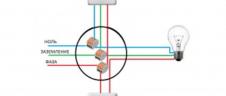
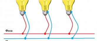
To connect a block with a two-key switch for lighting fixtures in the bathroom and bathroom, you need to lay five wires from the electrical box to it.
- The grounding conductor in the diagram is shown in light green, the zero is blue. These two conductors go directly from the distribution box to the outlet.
- The phase is indicated in red. This conductor is connected to the socket, then with a jumper - to the common contact of the incoming phase of the switch.
- The remaining two wires are connected to two switched contacts. Through them, the phase is connected to the lighting fixtures when the keys are pressed. These are lamps in the bathroom and bathroom. This circuit provides a constant phase, zero and grounding on the socket, and a phase on the lower contact of the switch keys (zero goes to the lighting fixture). On the upper contact, the phase appears when the keys are pressed.
Two twists of wires are made in the junction box. In the diagram they are indicated in beige and yellow. The switched phases are twisted from the switch to the phase conductors going to the lamps. The neutral and grounding conductor are taken in the distribution box from the contacts to which the socket in the block is connected.
Important! To change the order of operation of the keys, you need to swap the beige and yellow wires on the switch
If you plan to install a single-key switch, beige or yellow conductors must be excluded from the circuit.
Using a three-key product requires the use of a 6-core cable. The sixth core of the cable is connected to the third switched contact from above along with the beige and yellow conductors.
Combination appliances are increasingly being used to save space. As an example, a socket with a switch in one housing, installed in a socket box and serving two purposes at the same time: for connecting various devices using an electrical plug, and for turning on the light.
The advantage of this combination is that only one socket box is required, and as a result, one recess in the wall. It is also sufficient to supply only one cable with the required number of cores.
- Basic connection options Single-key option
- Two-key block
Installing a single-key unit
Instructions:
- When carrying out installation work on installing a single-key device
, 2 socket boxes are used, which have a design that allows them to be combined into one block. Socket boxes are installed in a recess in the wall, a 3-wire wire is inserted from the socket side, and a 1-wire wire is inserted from the switch side. - The socket boxes are fixed in the recess using gypsum mortar.
- When the solution is completely dry
, a 3-wire wire is connected to the outlet. In this case, you should carefully consider the phasing of this wire and connect the ground to the appropriate terminal. The phase wire must be connected to one of the socket terminals and brought to the switch input. “Ground” is connected to the third free terminal of the socket. - At the output of the switch,
a single-core wire is connected, which will be directed through a groove to the lamp. - After the wires are connected
, it is necessary to install the inner part into the socket boxes and, using a screw sliding mechanism, securely fasten it into the inside of the socket boxes. - Then the final stage of installing such a device is carried out.
The decorative plastic trim is screwed to the inside using bolts. On the switch side, fastening is often carried out using a latch.
Connecting the socket and switch
When connecting a socket and switch, just look at their connection diagrams and everything will fall into place. You should also consider the wiring diagrams for sockets with single, double and triple switches.
Usually, the problem of a person who just wants to replace the switch-socket unit is that he sees only a bundle of wires, which does not give him the overall picture, and therefore prevents him from correctly orienting himself. It may also be that the previous installation was made with incorrect phasing, which also does not add clarity. So enough words, let's figure it out.
Connection diagram for a socket with a single-key switch
The switch is turned off (zero comes to its input through the light bulb)
The switch is on (through it the phase is supplied to the light bulb)
As we can see from the diagram for connecting a socket with a switch, we need three wires: one is where the phase comes in, the other is zero, and the third is where the phase returns through a jumper to the input of the switch, powering the lamp bulb.
It should be noted that the first three pictures (top) are with the correct connection, that is, zero from the junction box goes directly to the lamp.
Then in the connection box for the socket and switch we see three wires. Two, on which there is a zero (we get one zero through the connected lamp), and the other with a phase. This is provided that a working lamp is connected.
When replacing a block, we can (after de-energizing the line) simply repeat the connection (by adding a similar block or socket with a switch). But, if this is not possible, we need to determine exactly where which wire is. To do this, having de-energized the line, we make a braid.
Photo of a three-wire braid.
It will help us avoid shorting the wires and will give us the opportunity, if necessary, to place the wires in the sequence we need.
Then we turn on the line and use the indicator to find the phase, through it (the phase) we determine the direct zero with a control light (the control light glows at full intensity), the zero and the phase are connected to the socket, the other wire through the switch (the phase is supplied by a jumper to the switch input) should power the lamp.
When you touch it (the remaining wire), the control lamp glows at the incandescent level, and the lamp lights up weakly (if an incandescent lamp is connected) or lights up at full power (modern lamps).
Having decided on the wires, we de-energize the line and connect the socket-switch unit. Once assembled, turn it on and check its functionality.
Connection diagram for a socket with a single-key switch with incorrect phasing
Incorrect phasing is easily determined by the fact that the indicator will show two wires with a phase. All actions remain the same as described above with the only difference being that now the direct phase is located (searched for) through zero, and it (zero) is supplied to the switch input through a jumper.
You may come across a situation where there are not three, but four wires, do not be alarmed, it means that one wire is either not working, or a pair is taken by the core (two wires are simply connected together). Just insulate the wire you don't need and that's it.
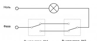
Connection diagram for a socket with a two-button switch
The switch is turned off (zero comes to its input through the light bulbs)
The switch is on (through it the phase is supplied to the light bulbs)
As you can see, everything is the same, only one more wire has been added. Don't forget about the braid.
Photo of a braid with four wires.
Connection diagram for a socket with a three-button switch
The switch is turned off (zero comes to its input through the light bulbs)
The switch is on (through it the phase is supplied to the light bulbs)
Photo of a five-wire braid.
The circuit does not become much more complicated when connecting a socket and a three-key switch, but if you have understood the previous circuits, then this one will not be difficult for you.
In practice, here, too, there may be not five, but six wires, but this means that the electrician simply did not want to separate one wire from the double one and one wire is either not working, or the pair is taken by the core.
How to connect a socket with a switch | Video explanation
That's all, good luck with your installation!
In the previous article, I talked about how single or double electrical sockets are connected to electrical wiring or to each other using a cable. Now I will tell you in detail how to correctly connect blocks consisting of a socket + light switch or three or four sockets.
Take it into account. that in one block under one cover not only switches, electrical sockets are combined, but also, if necessary, telephone and computer ones.
Before starting work on connecting electrical outlets, you must turn off the power supply automatically and make sure that there is no voltage using an indicator screwdriver.
We mount installation elements
For maximum clarity and clarity, we will analyze the full circuit installation cycle from start to finish. Thanks to this, we will give the most detailed answer to the question of how to connect an outlet with a switch. As an example, let’s take a diagram of hidden electrical wiring, something that is usually located under a layer of plaster.
We install the distribution box.
Next we need two sockets. Detailed instructions for installing a socket box (mounting cup) are described here.
We will install a switch in one, and a socket in the other.
Now let's mount the DIN rail, in our case it will act as part of the power cabinet; a circuit breaker will be installed on it, which will protect the electrical circuit from short circuits and overloads, which have such a detrimental effect on all elements of the circuit.
The preparatory work can be considered completed.
The last detail that completes the first stage of installation is the lighting element. In our example, it will be a light bulb with a socket, clearly, simply and clearly. Therefore, we will move its installation to stage number two.
Radio communication
We carefully insulate all twists using electrical tape. If you want to expand your circuit by connecting an additional light bulb or, for example, adding a socket, you can use a double or triple switch, here is how to do this.
Do not twist aluminum or copper wires!
This is an extremely unstable compound that quickly oxidizes and can not only fail, but also ignite. To connect such wires, use special terminal blocks. In an electrical store they are presented in a wide range. According to the rules of good manners and for safety reasons, try to use blocks instead of twisting wires everywhere.
If you did everything right, you can be proud of your work. If not... well, finally call an electrician.
I really hope that the article will be useful to you and that everything will work out for you.
Perhaps I forgot to say something important that seems self-evident to me and not at all clear to you. Therefore, I will wait for your comments below and will be happy to answer questions, supplement and correct the article if necessary.
Thank you for your attention!
Device selection
Since the choice is quite large, you can find a model that matches the interior of the room . The devices also differ functionally:
- Regular switches.
- Devices with an indicator that can turn on in the dark to indicate its location or indicate which key is on.
- Pass-through switches. They are installed in different places in long corridors or passages, on stairs, on different floors, etc. Through them you can control one or a group of lamps from different places.
There should be no scratches, burrs, abrasions or other damage on the body of the product. The keys should be easy to switch with characteristic clicks, and the terminals should firmly fix the connected wires. Self-clamping terminals work reliably and are more convenient to use. Just insert the wire into the hole and it will be fixed
It is important to remove it correctly if necessary. For this purpose, the device has special latches that can be pressed out. If you pull the wire out of the hole, the connector may fail.
If you pull the wire out of the hole, the connector may become damaged.
Connecting the switch through the distribution box.
Connecting the power source to the electrical consumer via a single-key switch is quite easy. There are 2 wires coming from the electrical panel - zero and phase. Zero is marked in blue, phase in red. Picture 3 shows a circuit diagram of a switch with wires of different colors.
The phase must pass through the switch, during the operation of which a break/connection must be made, namely the phase, and not the zero. It is easy to determine in which wire the phase is located, when the network is turned on, you need to touch both wires with an indicator screwdriver, one by one, where the red light indicator lights up there will be a phase.
If zero goes to the switch, then the wiring will be energized after turning off the electricity, and when replacing lighting elements you can get an electric shock. Ideally, current should flow to the light bulb in the following sequence - phase goes to the central contact of the light bulb, zero goes to the base. The circuit breaker diagram presented by the manufacturer of electrical appliances always involves disconnecting the phase.
To connect the phase wire to the switch itself, you must:
- Using a screwdriver, remove the switch key and unscrew the screws securing the housing;
- strip the phase wire from both ends, and using fixing screws and press washers, clamp it between the contacts of the switch.
The wire coming from the electrical panel should be attached to the bottom of the switch, and the wire coming from the lamp should be connected to the top.
The switch circuit consists of two wires coming from a network with a voltage of 220 V; to install a new connection, you can purchase wires of different colors, for example: red and blue. Which will pass through the distribution box, and the zero will go to the lighting element (electric lamp, or several lamps connected in parallel), and the phase will pass through the switch.
Using a knife, you need to evenly remove (strip) the insulation from each end of the wire, by 3 - 4 cm. Using pliers/pliers, twist the wires together. The neutral wire coming from the network with the neutral wire going to the light bulb, and connect the phase wire to the wire coming from the switch.
The principle of operation of the switch circuit is that when the switch key is pressed, the phase wire is connected, and electricity is supplied to the light source. The neutral wire goes, without a break, to the source.
The final stage of work will be insulating the electrical wiring. To do this, it is necessary to apply a solution of soldering acid or rosin to the contacts connected to each other, then carry out the tinning procedure using a soldering iron, covering the connections with solder.
After the service, it is necessary to insulate the contacts by wrapping them with special PVC tape. The box body must be closed with a plastic plug.
Scheme for connecting a circuit breaker device through a socket
In order to connect a switch using a socket, a standard connection diagram is used. Important! There is always a break in the phase conductor in the breaker, and the zero goes directly to the light source:
- A distribution box is installed into which wires are fed from the existing outlet (the room must first be de-energized), wires going to the switch, and a wire from the lamp.
- We connect one core from the source of electricity consumption to zero, the phase must be connected to the switch; if it goes through the junction box, then it is connected to the core from the switch.
Switch connection diagram
In the presented diagram, the phase wire goes from the light bulb directly to the breaker; when it is in the “on” position, electricity is consumed; when in the “off” position, the load does not receive electricity.
How to choose the wire cross-section?
Often the electrical connection of a source of energy consumption, for example, a sconce from an outlet, occurs to install additional lighting, in our case it can be one or more sconces, for this reason the current is low and it is possible to select wires of the desired cross-section, but there are nuances:
- according to safety requirements and PUE, for these purposes it is impossible to use a wire with a copper conductor cross-section of less than one square millimeter;
- and a wire with an aluminum core of at least two and a half square millimeters.
When choosing a wire, you need to take into account how it is laid, so there are certain conditions for open laying:
- for a copper wire, the minimum cross-section is 1.5 square millimeters;
- The minimum value of an aluminum core is 4.0 square millimeters.
To lay a wire along the outer wall of a house or building, there are the following requirements:
- for wires with copper conductors - 2.5 square millimeters;
- for aluminum wire cores - 4.0 square millimeters.
How to independently connect a light source from a switch?
One of the simple ways, according to experts, is to connect the sconce to the circuit through a switch powered by an outlet using neutral and phase wires; this is especially beneficial when the lamp is located close to the switch.
To complete this work you need to do the following:
- Carry out installation work to install the lighting source and switch, then carry out the steps to connect them.
- From the socket from which we will connect our voltage breaker, we remove the voltage using a machine in the panel (usually the wiring is carried out according to consumption groups), and check with a “probe” for the absence of a phase.
Socket connection diagram
- Open the socket; if the work on its connection is carried out with a copper wire with a color difference, then:
- zero – blue wire;
- grounding – second wire with double color (yellow-green);
- phase is the third wire, it may be brown.
If there is no color difference and the connection is made with an aluminum wire, you need to briefly apply voltage to the socket and use a “probe” to determine the phase of the electrically conductive wire.
- We connect the wire from the switch (to its input), which is already connected to the breaker, to the socket phase, and connect the wire from the lamp to the output from the switch.
- When you don't know how to connect a double switch, the solution is the same, but from the output of the electrical circuit interrupter, each phase wire goes to its own light source, or for a chandelier to its own power consumption bulbs.
- To the neutral wire of the socket we connect the neutral wire of the switch to the light bulb; if the socket has a grounding wire, we connect it to the grounding wire from the lighting source.
- After this, the wiring is laid and all connections are insulated, as well as the assembled circuit is tested.
If the switch is being added to an existing outlet
Minimizing the consequences - replacing the socket with a block. The procedure itself is simple; we drill a hole nearby for the box and carefully install the new module.
There is no need to install a power incoming cable; it is already in the socket. But the output wiring, to the lighting device, will have to be extended. This is an individual decision, there is no universal way. The connection diagram is very simple: both the neutral and phase wires are laid not from the box, but from the socket box.
Naturally, you will have to install contact blocks. Although many connect the output wire directly to the socket contacts: some models allow such a connection.
If there are several sockets in a group, you can replace any of them with a common block (socket - switch). You simply choose a convenient location (from which you can run the wire to the lamp) and connect the switch to the outlet.
If you need to organize an additional light point in the hallway, you can use wall sconces. They are placed in close proximity to the outlet-switch block, and you do not have to destroy a large piece of the wall for wiring.
General safety rules
Of course, before starting such work (especially on a completed power supply system), you should de-energize the line and check that there is no voltage. Selecting a power cable will not cause any difficulties: a cross-section of 1.5 mm² is sufficient for organizing lighting. Since we are connecting the switch to the socket, and not vice versa, the primary (socket) cable will be more powerful: 2.5 mm².
Installation sequence
There are no fundamental differences in connecting conventional and combined electrical fittings. For most modern interlocked electrical appliances, the fit size of the internal part of the unit, intended for hidden wiring, corresponds to the size of single sockets and switches.
The only thing that may be required when laying out a cable with a larger cross-section, which is necessary to connect three sockets at the same time, is punching a groove of a larger cross-section.
The approximate sequence of operations when connecting a combined unit is as follows:
- Markings are made for the laying of the wire (cable) indicating the installation locations of the mounting boxes into which the interlocked electrical fittings will be attached.
- A hole is drilled at the location where the box is installed using a drill bit installed in an electric drill.
- In the box it is necessary to break out the perforated plugs of the holes in the places where the cable is inserted.
- The stripped ends of the wire are placed inside the boxes.
- The boxes are fixed in the wall panel.
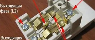
- After removing the cover from the socket block, connect the wires to its terminals.
- The block is installed inside the box and secured in it.
- To mask the installation gaps, a decorative panel is installed on top of the installed and connected socket-switch unit.
When choosing a specific model, there may be some installation features, however, the connection sequence does not differ from that described above.
Connection from a single-key unit
Connection diagram for a socket with a single-key switch
The most widely used units are electrical fittings in which one or more sockets are interlocked with a single-key switch.
In most models, several sockets have a single connection - a group of two terminal clamps for phase and zero, and the phase terminal has a jumper for one of the switch contacts.
The sequence of operations is as follows:
- From the apartment distribution panel to the distribution box, a two-core cable is supplied, supplying phase and zero.
- In the same box you need to insert three wires from the “socket-switch” block, and two wires from the lighting fixture.
- In the distribution box, the phase wire is connected to the wire coming from the socket terminal.
- The neutral wire from the lighting fixture is connected in the box to the “zero” from the distribution panel, and the second wire from the lamp is connected to the conductor connected to the free contact of the switch.
- If the socket in the block has a ground connection (“European standard”), then it is necessary to lay a separate wire to the pinching contact in the distribution box.
Connecting a multi-key switch will differ only in the number of conductors connecting the contacts of the switch to the lighting device.
Blocks with LED backlighting of circuits are technically no different from conventional interlocked electrical fittings. At the same time, the LED power supply circuit is built into the design of the device and does not require any additional connection.
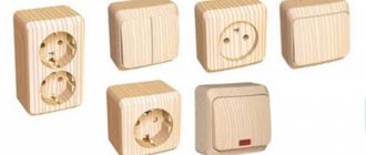
Types of sockets
Devices that have reached the end of their service life require replacement with new ones. This is necessary to avoid some dangerous moments - short circuits and electric shock to residents. Before installing an electrical outlet, you need to select the most suitable model that meets specific technical requirements.
Designer sockets
On the modern market you can find electrical appliances of various materials, quality, design, and installation methods. When purchasing, the level of security and the way in which the outlet will be mounted also play an important role.
According to the installation method, sockets are divided into
- Overhead options. This option is ideal for wooden houses, since the electrical equipment is located inside and not outside, which protects against fire hazards. Their main meaning is that the contacts and wires in a surface-type socket are located outside the wall, in a protective casing made of dielectric materials. Decoratively disguised electrical wiring is also supplied to them from outside the wall.
- Built-in models. Such devices are intended for installation inside brick, concrete or plasterboard walls. Before connecting a built-in socket, you need to make a recess in the wall of a certain diameter and depth. A fastening element is inserted into it - a glass-socket box, in which the electrical appliance is secured. The difference between such sockets is that they will not extend beyond the surface of the wall, with the exception of the external decorative trim. The wiring to them is supplied either under the facing material (plasterboard, wall panels) or in grooves. Grooves are specially made deep grooves in the wall where wires are laid, after which they are sealed with plaster or putty.
Types of sockets by type of wiring
- Screw. Attached to terminals using twist-on screw terminals.
- Spring. With handy clamps that hold the wires to the terminals instead of screws.
Surface-mounted socket type
By number of contacts
Sockets are divided into two-phase and three-phase. The first ones are intended for houses in which the electrical wiring consists of only two wires, a phase and a neutral. Three-phase ones are installed in the place where the third, grounding wire enters the wiring. We would recommend such models for household appliances, for example, for washing machines, and they are also well suited for computer system units.
Types of devices and their features
There are quite a lot of varieties of plug sockets and blocks. Each type has its own design features and purpose.
- Hidden devices are mounted directly into the wall - in special socket boxes.
- Open devices are produced for those apartments where the electrical wiring is not hidden in the wall.
- Retractable socket blocks are mounted in a table or other furniture. Their convenience lies in the fact that after use, the devices can be easily hidden from prying eyes and playful children’s hands.
The devices differ in the method of clamping the contacts. It comes in screw and spring types. In the first case, the conductor is fixed with a screw, in the second - with a spring. The latter are more reliable, but they are not so easy to find on sale. The devices are fixed to the walls in three ways - claws with jagged edges, self-tapping screws or a special plate - a support that facilitates both installation and dismantling of the socket.
In addition to conventional, inexpensive devices, there are models equipped with grounding contacts. These petals are located in the upper and lower parts, and a grounding wire is attached to them. To ensure safety, sockets are equipped with curtains or protective covers.
Main popular types
These include:
- type “C”, it has 2 contacts - phase and zero, usually purchased if intended for low or medium power equipment;
- type “F”, in addition to the traditional pair, is equipped with one more contact - a grounding one; these sockets are becoming more popular, since a grounding loop has become the norm for apartments in new buildings;
- Type “E”, which differs from the previous one only in the shape of the grounding contact, is a pin, the same as the elements of the socket plug.
The last type is less common than the others, since it is less convenient to use: turning the plug 180° with such a socket is impossible.
The security of the case is the next difference between the models. The degree of security is indicated by the IP index and a two-digit number following these letters. The first number indicates the class of protection against dust and solids, the second - against moisture.
- For ordinary living rooms, IP22 or IP33 class models are sufficient.
- It is recommended to buy IP43 for children, as these sockets are equipped with covers/curtains that block the sockets when the equipment is not in use.
- IP44 is the minimum required for bathrooms, kitchens, and baths. Not only strong humidity, but also splashes of water can pose a threat. They are suitable for installation in basements without heating.
Installing an outlet on an open balcony is a sufficient reason to purchase a product with a higher degree of protection, this is at least IP55.
Connection diagram
The electrical circuit represents a parallel connection to the power source of a lighting fixture with a light bulb, a switch and a socket.
Preparatory work
After turning off the machine, you need to once again make sure that there is no voltage, now using an indicator screwdriver. First, check its working condition in an area that is known to be energized, for example, at the entrance to the machine. The indicator lights up after touching the phase, which means it is in good condition. Now touch the indicator screwdriver to the cores of the power wire, which is brought into the apartment from the machine; there should be no glow. This means that the tension has been relieved and work can begin.
Lay the wires in the grooves made, leading them to the wall holes. At the same time, leave the ends of 10-15 cm for cutting the cores, do not regret it, it is better to make a slightly larger reserve than to suffer later when connecting and connecting. Install a distribution box and socket boxes in the holes; use plaster or alabaster to securely fix them.
Electric installation work
Place a two-wire cable from the mains supply (phase and neutral) into the junction box. Three wires must be laid from the box: one to the switch, the second to the lamp, the third to the outlet.
For a wire whose cores have different insulation colors, red indicates phase, blue indicates zero.
The switch has an input and output contact; a phase conductor is connected to the input. Connect the second core to the output contact of the switch.
A two-wire wire must also be laid to the lamp. The lamp socket has two contacts. The central spring contact (phase) is used to directly supply voltage to the light bulb. The side contact in the socket is zero, the lamp will come into contact with it after screwing in with its base.
Another two-wire wire is laid from the junction box to the outlet. This switching device has a contact part consisting of two terminals to which phase and zero are connected.
The connection diagram for the switch, lamp and socket in the distribution box is as follows:
- Connect the neutral conductor from the supply wire with the neutral conductors going to the lamp and socket.
- Connect the phase conductor from the supply wire with the phase conductors going to the switch and socket.
- Connect the remaining core from the output contact of the switch to the phase core of the lamp.
All connections must be made as firmly as possible to ensure reliable contact. This can be done the old fashioned way - by twisting, which it is also advisable to solder on top. There are also more modern devices: special blocks (in which the wire is clamped under a screw) or PPE (connecting insulating clamps).
For more information about connecting wires in a junction box, watch this video:
Checking the circuit and completing the work
Move all the twists in different directions so that they do not touch each other and check the operation of the assembled circuit. Turn on the input circuit breaker for the apartment, thereby supplying voltage from the power source to the newly mounted distribution box. The switch is in the “off” position, the lamp does not light, which means everything is correct, the phase is open. Now press the switch key to the “on” position, the electrical circuit is closed and voltage is supplied through it from the power source to the lamp, the light bulb lights up. There will be constant voltage at the outlet; you can check its operation by connecting any electrical appliance. Plug the hair dryer, radio or electric kettle into the outlet and check its operation.
All that remains is to securely place the switch and socket in the socket boxes, secure them, and put protective covers on top. The distribution box is also covered with a lid; during any repair work, never hide it under wallpaper or plaster. Remember, the distribution box should always be accessible, no matter how much it spoils the overall appearance of your room.
Also keep in mind that if the lighting fixture and socket are structurally grounded, then their electrical circuit will require a three-core wire. The same wire of three cores should also come to the junction box from the power source. Typically, the grounding conductor is indicated in green or yellow; in the same way, in the box you will need to connect three protective grounding conductors into one twist - from the power source, socket and lamp.
Laying the wires
First of all, let's connect the wire feeding the junction box. In our example, we use a wire of the VVGngP brand; a three-core wire with a cross-section of 2.5 squares is used as the power supply. The cross section was selected using the calculation method based on the load on the chain; you can easily perform these calculations on your own. Here you will find a detailed description of how to independently calculate the cross-section of a wire, I assure you there is nothing complicated here.
On both sides it is necessary to leave a reserve of wire for connecting electrical wiring elements (breaker, socket, switch) of 10-12 centimeters, in the junction box 10-15 centimeters. Wires that are too short will be inconvenient to connect and connect, so it’s better not to save much.
Next, let's connect the wire to the socket.
Here you will need a wire with a core cross-section of 2.5 square.
1.5 square meters per switch.
Now, let’s lay the wire for the lighting; for us it’s a light bulb with a socket.
We have laid all the wires necessary to complete the circuit, let's move on to the third stage.
If the switch is being added to an existing outlet
Minimizing the consequences - replacing the socket with a block. The procedure itself is simple; we drill a hole nearby for the box and carefully install the new module.
There is no need to install a power incoming cable; it is already in the socket. But the output wiring, to the lighting device, will have to be extended. This is an individual decision, there is no universal way. The connection diagram is very simple: both the neutral and phase wires are laid not from the box, but from the socket box.
Naturally, you will have to install contact blocks. Although many connect the output wire directly to the socket contacts: some models allow such a connection.
If there are several sockets in a group, you can replace any of them with a common block (socket - switch). You simply choose a convenient location (from which you can run the wire to the lamp) and connect the switch to the outlet.
If you need to organize an additional light point in the hallway, you can use wall sconces. They are placed in close proximity to the outlet-switch block, and you do not have to destroy a large piece of the wall for wiring.
General safety rules
Of course, before starting such work (especially on a completed power supply system), you should de-energize the line and check that there is no voltage. Selecting a power cable will not cause any difficulties: a cross-section of 1.5 mm² is sufficient for organizing lighting. Since we are connecting the switch to the socket, and not vice versa, the primary (socket) cable will be more powerful: 2.5 mm².
Installation
If the master decides to carry out the installation himself, he does not need to have any special specialized tool. It is enough for him to have:
electric drill; drill bit; 1-2 screwdrivers (handles must be insulated); pliers; nippers (side cutters).
Preliminary preparation for all structural options of these blocks is as follows.
The power supply must be turned off. Appropriate markings are made at the selected location on the wall. At the required points in the wall, mounting holes are drilled using a crown, after which a niche is made (if the wiring is hidden). Perforated holes for cables are broken out on the box body.
Single-key block
A socket combined with a 1-key switch in one housing is the most popular. Connecting such a pair occurs like this (diagram 1):
- The general apartment panel is connected to the distribution box with a two-core cable (“phase” and “zero”).
- A double wire connects the light source to the distribution box.
- 3 wires from the socket-switch pair are inserted into the box.
- You must make sure that the wire goes from the phase terminal in the box to the socket terminal, and from the socket to one of the switch contacts.
- The lighting device connected to the distribution box is connected with one of its wires to the “zero”, and the other goes to the free terminal of the switch.
- If the Eurostandard type unit has a ground connection, it must be connected to the ground terminal in the box.
Two-key device
When installing such a unit, it becomes possible, in addition to connecting any consumers through an outlet, to control the light in at least two different rooms or different light sources in a common room.
To perform such an installation (diagram 2), you need to do the following:
- 5 wires are supplied from the distribution box to the paired block.
- Only the neutral wire and ground wire are connected to the outlet.
- The “phase” is supplied to the double switch through a special jumper in the switching block.
- 2 free wires are connected to 2 switching terminals of the switch.
- In the distribution box, twists are made from the wires supplying the “phase” and the wires going to the lamps in different rooms.
We present to your attention a connection diagram for a two-gang switch and two sockets in a distribution box:
Whatever configuration the master chooses, he must thoroughly study and work out the schematic diagram of all connections and connections before starting installation.
As a result, the correct installation of a socket connected to a switch is not only the high-quality operation of electrical appliances, but also the safety of the home and people.
Where is it used?
Let's consider a situation where it is necessary to connect some new lamp or sconce from an outlet through a switch. There are cases when the renovation has already been completed, but there is a need for additional lighting. In order not to pull wires from the junction box and not to ditch all the walls, the additional switch and lighting fixture are connected from an outlet that is located nearby.
The socket represents two potentials, one of which we will take for the switch (phase), the second we will extend to the light bulb (zero).
This option is widely used in kitchens. On the working wall (also called an apron) there are several sockets for connecting many household kitchen appliances. It is advisable to place a switch in one frame, with the help of which the lighting of the kitchen table will be turned on and off.
Keep in mind! Such a switching scheme will be rational only if the lamp is located in close proximity to the socket. If the lighting fixture is located far away, make all connections through the junction box.
Conclusions and videos on the topic
After familiarizing yourself with the rules for connecting a switch from a socket, the user will not have any difficulty in choosing a unit suitable for his needs (based on the number of switched loads). In addition, he will be able to try in practice to master the techniques of working with similar electrical products.
Experts advise starting to master the technique of connecting them with the simplest combination of “socket plus single-key switch”, and then moving on to more complex combinations. For all users who want to learn the basic techniques of such operations and fully understand how to properly connect a combined unit, video reviews will provide significant assistance. The latter are presented in large quantities on the pages of relevant Internet resources.
Please click on one of the buttons to find out if the article helped or not.
Useful tips
During the installation of the switch there are several very important points that must be remembered. Moreover, this applies not only to the installation process itself, but also to the selection of the necessary equipment. By following a few simple rules, the system will be more reliable and secure.
Below is a list of recommendations and rules that must be followed for safety reasons:
- all work on connecting equipment in the distribution panel must be carried out by qualified electricians; in the absence of knowledge and skills in this area, interfering with the security system located on the site is unacceptable;
- any actions should be carried out exclusively after a power outage at the general apartment switchboard, and before carrying out any operations with wires, you should make sure that the electrical circuit is de-energized (you can use a probe for this);
- in the case when it is planned to connect and install a contactless device or a device with a dimmer, a detailed study of the circuit is required, since the basic installation principle may differ significantly from the installation of a two-key switch, and may have many nuances.
To summarize, connecting a two-key switch to two light bulbs is quite simple, especially if you have at least some skills in this area. But if you have no experience working with electrical equipment, it is better to leave this matter in the hands of professionals. Remember that working with electrical power can be life-threatening. Improperly installed wiring may cause a short circuit and fire. Don't risk your life and contact specialists!
Sources
- https://YaElectrik.ru/elektroprovodka/shema-podklyucheniya-dvuhklavishnogo-vyklyuchatelya
- https://www.asutpp.ru/shema-podklyucheniya-dvuhklavishnogo-vyklyuchatelya-na-dve-lampochki.html
- https://pro-instrymenti.ru/elektrika/kak-podklyuchit-dvojnoj-vyklyuchatel-na-dve-lampochki-shema-podklyucheniya/
- https://remont-kak.ru/renovation/electrical/kak-podklyuchit-dvuhklavishnyy-vyklyuchatel
- https://sovet-ingenera.com/elektrika/rozetk-vykl/podklyuchenie-vyklyuchatelya-sveta-s-dvumya-klavishami.html
- https://first-apartment.ru/kak-podklyuchit-vyklyuchatel-s-dvumya-klavishami.html
- https://vilki-rozetki.ru/elektroprovodka/kak-podklyuchit-vyklyuchatel-dvojnoj
- https://sovet-ingenera.com/elektrika/rozetk-vykl/podklyuchit-dvojnoj-vyklyuchatel-na-dve-lampochki.html
Jan 25, 2021
Electrical wiring project
To begin with, they draw up an electrical wiring project; it is best if the project is drawn up for you by professionals. But if you have experience and the necessary knowledge, then you can draw it up yourself.
You need to know that Russian standards are very different from foreign standards, which means that foreign wiring diagrams cannot be used in our country. All electrical installations in the house are planned at the initial stage; for this purpose, draw a house plan and indicate on it the places where there will be switches, sockets, chandeliers, etc.
At this stage, it is very important to create a diagram where the locations of the devices will be indicated.
The next step will be to indicate where the wires will be laid in the house.
After all the above manipulations, carry out the wiring.
There are three types of wiring and connections:
- Consistent;
- Parallel;
- Mixed.
A more economical option is considered mixed.
To make their work easier, they distribute the load. For example:
- Lighting of rooms, corridor and kitchen;
- Bath and toilet lighting;
- Sockets in rooms and corridors;
- Sockets in the kitchen.
This option is a simple ungrouping of electricity consumers and the fewer groups, the more economically the material will be used. In order to simplify the installation of wiring, its installation is carried out in floor slabs. In the diagram, such wiring is marked with dotted lines.
Calculation of current consumption
When conducting wiring, it is necessary to take into account the current strength that will have to flow through the network, that is, this is the ratio of the total power of all consumers to the voltage. In houses and apartments, the maximum current consumption does not reach twenty-five Amperes.
All materials must be selected according to this parameter. The cross-section of the wires depends on the current strength.
If you calculate that your current consumption is 16 Amps, then you cannot install fuses with the same operating current value.
It is necessary to take a larger standard value than the calculated one.
Connecting with the wrong cable
Strange as it may seem, many people still lay lighting lines with a two-core cable. Although the PUE and clause 7.1.36 tells us the opposite.
Moreover, they choose any cross-section of this wire, from 0.5mm2 to 1.0mm2.
In addition, for all electricians, it has long been an axiom that brands such as ShVVP or PVS are prohibited as wiring for stationary lighting. However, they can also be found in apartment renovations.
Therefore, remember once and for all - the cable for connecting lighting in apartments must be:
three-wire
cross section of at least 1.5mm2
brands VVGng-Ls or NYM
Many will ask, why do we need a three-core cable if all the lamps in the apartment are plastic and there is simply nowhere to connect the ground wire?
In the PUE there is a corresponding clause in this regard 7.1.70
It turns out that even if your lamp is not equipped with contacts for the protective conductor, this is not a cancellation for clause 7.1.36. That is, the wiring to all light bulbs must be three-wire.
Some electricians recommend carefully wrapping the unused third grounding conductor near the light bulb socket around the phase and neutral. Approximately as follows.
In this case, if the insulation on the conductors is damaged, a leak will occur and the RCD will trip, protecting you from a possible fire. The same thing will happen if you accidentally damage the cable insulation without shorting a phase or zero.
That is why a three-wire circuit in lighting circuits is used to trigger differential protection when the short-circuit current is insufficient to trip the circuit breaker.
And the use of three cores is mandatory here.
Installation of an apartment or house electrical network
Before considering the issues of making changes to the existing network, let's understand how it works. After all, your ability to make changes to it directly depends on your understanding of this issue.
Main diagram of the apartment electrical network
First of all, let's determine how the wiring diagram for an apartment or house is made. This circuit begins in the input panel.
The photo shows a possible diagram of an apartment electrical network
- So, let's start with the introductory panel. It can be located in the entrance or directly in the apartment. In it you will find an input circuit breaker, which receives a power cable from the general house electrical network. Sometimes instead of a machine there are batch switches or even circuit breakers, but this is mainly in old houses.
- From the input circuit breaker the wires go to the meter, and from it to the group circuit breakers. Usually there are two or more of these groups. This amount directly depends on the possible loads in your apartment.
- Group circuit breakers divide the electrical network of your apartment or house into several groups that are not connected to each other. Groups can be formed according to the nature of the loads or the ease of installation. This is not a fundamental question. The only thing that the instructions prescribe is the division into different groups of electrical appliances in the bathroom and kitchen with electrical appliances in the living rooms.
- From group circuit breakers, wires go to one, two or more distribution boxes. They are directly connected to a group network of sockets and switches. This concentration of connections in one place makes it possible to simplify maintenance as much as possible and hide utility networks.
Connecting switches and sockets
In order to determine whether it is possible to connect an outlet from a switch, let's look at the features of their connection to the group supply wire. After all, starting from this, we can clearly imagine our future scheme.
Connecting the socket
- To connect the socket in accordance with clause 7.1.13 of the PUE, three wires are required. One of them is phase, the second is neutral and the third is protective grounding. These wires, in accordance with clause 1.1.30 of the PUE, must be marked with blue as the neutral wire, yellow-green as the protective grounding wire and any other color as the phase wire.
- The phase and neutral wires from the supply group wire in the distribution box are connected to the power contacts of the socket. Protective grounding to grounding contacts.
Switch connection
- Connecting the switch is even easier to do yourself. After all, this requires only two wires. Moreover, both of them will be phase. The first wire is connected to the phase conductor of the group line and to the switch input.
- The second wire from the switch output goes to the distribution box, where it is connected to the phase wire of the lamp. The zero of the lamp is connected bypassing the switch, directly in the distribution box to the supply wire.
Connection diagrams
Several cables can come into the junction box.
Firstly, this is a three-wire power cable from the lighting circuit breaker installed in the electrical panel. Secondly, a 4-wire cable goes down to the three-key switch, which you have already connected from below.
Well, then there may be options. If you have one chandelier with 3, 6, 9 bulbs, then you can connect it with one single five or 4-core VVGnG-Ls cable with a cross-section of 1.5 mm2.
If you have three independent lamps, in different parts of the room or house, then you will have to run a separate 3-core cable to each of them. Let's consider the last option in more detail.
Welding
Using this method, at the end of the work you will receive an essentially solid cable. He will not be afraid of oxidation processes or any other negative impact characteristic of disconnected wires.
To complete the work you will need the following elements:
- welding machine;
- sandpaper;
- flux;
- personal protective equipment – gloves, goggles;
- carbon electrode.
At the first stage, you need to clean the cables from insulation and strip the wires until shiny using sandpaper. Then twist the wires together. The third step will be to fill the recess of the carbon electrode with flux.
Afterwards, it is necessary to put the welding machine into working condition, press the electrode to the place where the cables are twisted and hold it there until a ball is formed, in other words - a contact point.
The resulting contact point must be cleaned of flux and coated with a special varnish. At the final stage, you need to insulate the connection.
How to connect a single-key switch from an outlet
The classic option: a common zero bus from the distribution box is connected to a light point.
Grounding goes through the same cable channel (if used). But the phase wire does not go directly to the lighting fixture. A single-key switch (located in the same housing as the socket) breaks the circuit between the phase contact in the socket box and the light source. Quite a common scheme. Such a block can often be found in lighting stores.
Another application for such a module is a switchable socket. Let's say you have an electrical appliance that should be turned off at night or when leaving the room. This could be a router that distributes Wi-Fi. The unit itself is located high, so it is not always possible to use the standard power button. By clicking the switch key, you will de-energize the equipment without touching the circuit breaker in the distribution panel. Or, on the contrary: the device must be powered under certain conditions. For example, power supply for an alarm system.
In this case, the phase wire inside the block is simply opened by a switch, and the power wiring is connected as to a regular socket.
General provisions
Next, we will consider the most common schemes for powering the lighting elements of a room.
The features of creating such branches largely depend on the number of lamps connected to them, as well as their control using a switch.
But in any case, the created branch includes:
- Switch (one-, two-, three-key);
- Lamps with sockets;
- Junction box;
- Wires (two- and three-core).
A little about the features of the breaker.
Any switch has two outputs - input and output (there may be several of the latter).
Moreover, both of them belong to the same line, that is, if a phase is connected to the input terminal, then it will also be at the output.
By moving the key to a certain position, the contacts of these terminals are connected or disconnected, thereby closing or opening the circuit.
Before describing connection methods, let us immediately remind you of safety precautions when carrying out work.
To avoid electric shock, turn off the power supply and take steps to prevent accidental restoration of power before work is completed.
Step by step process
The algorithm for such work will look like this:
- De-energize your workplace by turning off the circuit breaker that directly supplies this room. If there is no panel with such a group division of rooms, then turn off the common input machine for the apartment. Use an indicator screwdriver to check that there is no voltage at the workplace.
- Near the socket, make a hole for the switch and fix the socket box in it. You will also need to make a small groove between the socket and the switch where the jumper wire will be laid.
- Install the lighting fixture in the desired location. Here you can see for yourself how it is more convenient for you to do it. You can also carefully punch a groove up to the lamp, lay a two-core wire in it, and then cover it with wallpaper. Or you can lay the wire in a plastic box, it also looks nice and neat.
- Remove the cover from the socket and pull out its contact part from the socket box. If you yourself installed this switching device in the past and observed the color designation of the wires, then the terminal to which the blue wire is connected will be zero, and the terminal with the white (red or brown) wire connected is a phase. In sockets with protective grounding there is also an additional terminal in the middle where the grounding conductor is connected; it is usually made in yellow-green color. If you do not know exactly where the phase and zero are, this must be determined by applying voltage to the disassembled socket and touching the terminals with an indicator screwdriver. The luminous window on the screwdriver means that you are touching the phase wire, respectively, the second wire will be neutral.
- Connect a wire core to the phase terminal of the socket, the second end of which should be connected to the input contact of the switch. Lay this wire in the groove between the holes and fix it with a solution.
- Connect a wire to the neutral terminal of the socket that will go to the neutral contact of the lamp socket. If the housing of the lighting device must be grounded, then the grounding conductor can also be pulled from the corresponding terminal of the socket, only in this case it will be necessary to lay a three-core wire to the lamp.
- A wire core is connected to the output contact of the switch, which will be the phase of the lamp.
- This completes the switching actions. All that remains is to fix the working parts of the switching devices in the socket boxes and put the protective frames on top. The last key is attached to the switch and the assembled circuit is tested in action.
- Apply voltage by turning on the input circuit breaker. Insert the plug of any household appliance into the socket, it should work. Now press the switch key, the lamp in the lamp should light up.
This version discusses in detail how to install a switch with one key. In the same way, you can install a device with two or three keys, only a separate wire must go from each output contact of the switch to a certain group of lamps.
We looked at how you can connect a switch from an already installed outlet. Remember that this option in a household electrical network is the exception rather than the norm and is used in cases of extreme necessity.
Advantages and disadvantages of combined blocks
Before the advent of combined units, switching of sockets and switches was carried out through distribution boxes. These products themselves were installed separately in convenient places (according to the electrical design).
Connection diagram for socket and switch with two wires from the distribution box
Today, much attention is paid to saving space, as well as the effort and money spent on such installation.
Therefore, when arranging household electrical wiring today, paired and other complex structures are increasingly used, which have the following pros and cons:
Advantages and disadvantages
Connection diagrams for a switch from a socket are simpler
in this case, it is possible to save on wires that were previously laid to each element separately
The procedure for marking the space for mounted equipment is greatly simplified
there is no need to cut separate grooves for electrical wiring for a switch and a closed-type socket (when laying a route to the block, one three-core cable stretches)
Relatively high purchase cost
Impracticality (if one element of the block breaks, you have to replace the entire product)
Increased current load, forcing you to separately take into account the limiting parameters of the wires in the electrical circuit
The need to choose a special place to place the dimensional block (it cannot be installed arbitrarily, as it can spoil the appearance of the room)
If the position is not chosen correctly, it will be inconvenient to turn on the light (especially in complete darkness)
The big advantage of this arrangement option is the high speed of installation of the product at the installation site, which is explained by the minimum of preparatory operations.
However, this solution, called combined, has certain disadvantages.
Please note: The biggest disadvantage of combined devices is the need to completely replace them if one of the constituent elements fails.
The presence of serious shortcomings in the devices being evaluated for purchase forces the user to think about the correctness of the choice made.
Which antenna plug is better?
The answer is clear: the best of the three considered plugs for television coaxial cable is the F-plug. This is easy to see in the photographs above, even without special knowledge.
As you can see, the antenna plug of the old design and the Soviet antenna plug have a small section of the central core of the cable that is not covered by the shielding braid. This disrupts the uniformity of wave impedance, which leads to minor losses of the television signal.
The F-plug does not have an open section of the central core of the antenna cable. Another advantage of the antenna F-plug is ease of installation. With a minimum set of standard tools and no skills, almost anyone can correctly attach the antenna F-plug to the cable.
How to install the antenna plug on the cable
There is no need to invite specialists to connect the TV to the antenna cable. Every home craftsman can do this work independently using available tools if he follows the instructions below.
The voltage of an analog or digital television signal in an antenna cable is millionths of a volt, so an antenna cable connected to a cable network or another TV is not dangerous to humans. You can easily cut the cable without disconnecting its other end from the splitter or TV. When cutting a cable, an accidental short circuit between the central conductor and the shielding braid is also not dangerous.
How to install an F-plug on an antenna cable
The plugs are sold in three sizes for antenna cables of different diameters. When purchasing, make sure that the F-plug is suitable for your TV antenna cable. This type of plug is suitable for analogue, digital TV and satellite signals.
You can screw the F-plug onto the cable by cutting it in two ways, with the shielding braid wrapped in the diagram on the left side, and without wrapping it in the diagram on the right, in accordance with the cutting diagram below.
The F-plug will hold more securely if the shielding braid is twisted, but if you cannot screw it in, you can use the second method.
To cut a television cable, lightly pressing the knife so as not to damage the shielding braiding of the antenna cable, its outer shell is cut along a few centimeters.
After cutting the shell, it is bent to the side and cut off at the start of the cut.
The aluminum foil and copper braid are turned away. The screen in antenna cables comes in three versions: one copper braid, aluminum foil and on top of it a copper braid (as in my case), only aluminum foil.
Many people do not know that to give mechanical strength, the foil is coated on the inside with polyethylene.
It is impossible to clean the plastic. If you screw the plug onto the inside of the antenna cable foil, there will be no contact, or it will be very poor. To prevent this from happening, you need to bend half of the foil turned back, then the conductive side will be on the outside.
There are situations when the diameter of the hole in the internal thread F of the plug is larger than the diameter of the antenna cable. In this case, before wrapping the foil, you need to wind several layers of insulating tape onto the antenna cable to adjust the size of the cable. Then do everything as described. The insulation is removed from the central core using the technology described in the article “Preparing wires for installation.”
The F plug is screwed onto the foil “wrap onto the cable”.
The central core of the antenna cable is bitten off so that about 2–3 mm remains protruding.
The second half of the plug is screwed in until it stops, and the F-plug is ready for use.
There are times when, after inserting the antenna plug into the TV socket, the cable has to be bent at a right angle or it is impossible to install the TV close to the wall due to the interfering antenna cable. In this case, you can use an F-socket - a plug with an angled design.
The difference between the two described plugs is only in their shape. The technology for installing straight and angled plugs on a television cable is the same.
How to install an old design plug on an antenna cable
Before the advent of antenna F-plugs, plugs of a different design were used, which also did not require soldering, but were connected to the antenna cable using their own technology.
Before you begin installing the plug on the antenna cable, you need to hold it by the metal part and unscrew the plastic case by rotating counterclockwise. Then put the case on the cable so as not to forget.
The next stage is preparing the antenna cable for installation. To do this, use a knife blade to cut through its outer shell to a length of about a centimeter with light pressure. Next, remove the sheath and trim the shielding braid by 5 mm. Remove five millimeters of insulation from the central core. The antenna cable is now ready to be inserted into the plug.
When threading the cable into the plug, it is necessary to ensure that the conductors of the braided fasteners of the central core do not touch. Using pliers, the petals of the antenna plug are crimped around the shielding winding. There shouldn't be much effort. The main thing is to have reliable contact.
Next, screw in the screw securing the central core of the antenna cable until it stops.
The last step is to screw the plastic part onto the metal part of the plug and insert the plug into the TV socket.
Where to insert the antenna cable on the TV
Once the connector is installed on the cable, it can be connected to the TV. The socket for connecting the TV to an antenna or cable network is usually located on its back wall and is marked next to it in the form of the abbreviated inscription “ANT”.
In the photo on the right side you can see the socket for connecting the antenna. The socket is special, standard and differs from all other connectors and sockets available on the patch panel. Therefore, it is physically impossible to mistakenly insert the antenna plug into another socket. Any of the connectors, the installation of which is discussed in the article above, fits well into the television socket.
In modern televisions, to receive a television signal, two connectors are installed to connect an antenna: - cable (digital) television and a satellite antenna.
One, designated RF (ANT 1 IN), is designed to connect a digital television or cable network antenna; this is installed on all models of TVs, both old and modern. The second one began to be installed recently, LNB (ANT 2 IN with external thread) is intended for connecting a satellite dish.
If the TV supports the DVB-S2 standard, then the satellite dish can be connected without a receiver, directly to the LNB connector. To receive digital television channels from a television tower to an individual antenna, the TV must support the DVB-T2 standard. Therefore, when buying a TV, you need to pay special attention to the list of broadcasting standards that it supports.
To receive a signal from a given connector on the TV, you need to select the signal source Antenna or Satellite TV in its Menu and perform automatic or manual channel tuning.
How to connect an antenna cable to a TV without a plug
There are situations in life when you urgently need to connect an antenna cable to your TV, but you don’t have a plug at hand. You can temporarily connect the antenna cable without a plug. To do this, you must first remove the top sheath to a length of 5 cm, develop and unscrew the shielding braid, remove the insulation from the central core of the cable and bend the core itself into a loop. The width of the loop should be slightly larger than the hole in the central connector socket.
If the connector on the TV is like in the photo, then you need to put an insulating tube on the central contact. Next, the loop is inserted into the central contact, and the shielding braid is tucked into the connector using the blade of a screwdriver. The main thing is to prevent the shielding braided wires from coming into contact with the central core of the cable.
If the braid is aluminum, then you can insert it into the television connector and fill the free space with thin copper wires taken from any stranded copper wire. To prevent the wire from falling out of the TV connector, you can secure it with several toothpicks or matches. Such an improvised connector will serve quite reliably.
How to connect an antenna cable to a crab without a plug
The cable is prepared in the same way as for putting on an F-plug, the central core is inserted into the crab's F-connector, and the screen is put on the protruding part of the crab's connector and secured with any wire or clamp. As a last resort, you can fix the cable by tightly wrapping several layers of electrical tape. It will work no worse than with an F-connection.
If you use a clamp with a screw crimping device, the quality and reliability of the connection will be no worse than with an F-connector.
Construction and components
To thoroughly understand how to properly install a new outlet at home, you need to study a little about its components. All sockets are sold already assembled. Therefore, when installing it, you will have to unscrew everything yourself.
The main components of the socket are the base, the conductive part, and the decorative front panel. The base is made of ceramic or high-quality plastic. All elements are attached to it - conductive parts and the front cover.
Ceramic bases are considered more reliable, but they require particularly careful installation, because if damaged, you will have to buy a new socket.
The decorative overlay is designed to hide all working elements. It serves as a reliable insulator of the working part from external influences. Some models provide the ability to simply replace this part of the outlet.
Getting to know the internal structure of the outlet will help you better understand the process of connecting it correctly.
The working part of the socket consists of spring contacts and terminals to which electrical wires are connected. One of the important contacts is the grounding one.
The conductive elements are made of brass or bronze. The latter are better, but are extremely rare. Therefore, you should choose options made from tinned brass - they are more reliable than conventional brass, are better soldered and last longer.
Designer sockets allow you to make the interior of your home unforgettable. Their unusual performance adds its own flavor
Soldering
The sequence of actions will correspond to the previous method using a welding machine, the main difference is that the wires are connected to each other using solder, which is melted with a soldering iron.
- SIP wires: types, differences from cable, features and advantages
- What is a Power Cable?
- How to conveniently unwind a cable coil on site during electrical installation
The connection obtained by soldering is considered reliable and durable, but this method should not be used in places where the wires may become very hot. It is also not advisable to carry out soldering in places where there is a possibility of mechanical stress on the resulting connection.