General information
The passage of electric current through a conductor depends on its conductivity . This parameter is proportional to the current strength. In other words, it determines the ability of a substance to pass electricity through itself without loss. Conductivity depends on the physical properties of the material, temperature, and the degree of influence of external forces. Its inverse value is resistance, that is, a characteristic of a conductor that shows its ability to resist the passage of current.
The connection between the fundamental parameters of electric current was experimentally established by Simon Ohm. He found out that the current strength in a closed circuit is proportional to the potential difference (voltage) and inversely proportional to the resistance: I = U / R. So, if R is zero, then the current strength will be infinite.
The ability of substances to obstruct the passage of electric current is used in the construction of electrical circuits. So, a radio element, called a resistor, installed in a certain place in the electrical circuit, allows you to obtain the required voltage or current value at the load. The radio component is a two-terminal network that has a set resistance value or can change it.
A real closed electrical circuit consists of many active and passive radioelements. Each of them has some resistance value. In this case, we talk about the internal resistance of the device.
Calculation of the output characteristics of a circuit, namely current and voltage values, requires knowledge of the total resistance of the entire closed circuit. In other words, all elements, from the power source to the load, are replaced with equivalent resistors. For a circuit, first calculate the total resistance value, and then calculate the required characteristics. With respect to the current source, load and other elements, each resistor can be connected:
- sequentially;
- parallel.
The type of connection affects the total resistance. The formula for finding it can be quite cumbersome due to the mixed connection, so more often the calculation is carried out in several stages, at each of which one or more elements are combined.
Serial connection
For convenience, when depicting a branched electrical circuit, all resistances are drawn in the form of rectangles, which are resistors. Any such element can have two outputs. One is the beginning and the other is the end. Taking into account the above, we can formulate a definition for a serial connection of conductors: a connection in which the end of the previous element is connected to the beginning of the next one is called serial.
Any conductor has electrical resistance. The purpose of the conversion is to replace the alternating sequence with a single resistor. At the same time, in its electrical properties it should not differ from the entire chain. In simple words, this can be explained as follows: if you take two black boxes that have a pair of terminals each, and one will contain the entire electrical circuit, and the other will be its equivalent, then it will be impossible to determine which of them contains the circuit and which is the equivalent.
When connected in series, the following phenomena occur. Let there be a straight chain containing n resistors: R1 + R2 + … +Rn. Current strength is a quantity that is equal to the charge flowing per unit time. You can imagine that the electric current in the first resistor will be greater than in the second. As a result, a “traffic jam” will occur, and the speed of movement of the charges will slow down.
At the point of connection of the elements, electrons will accumulate, which will lead to an increase in voltage there. Accordingly, the current in the first resistor will decrease, and in the second, on the contrary, it will increase. This will lead to equalization of the number of charges passing through the resistors, so the current strength in almost an instant in the entire series circuit will become the same.
Voltage is the work done to transfer charge. According to the law of conservation of energy, its total value is equal to their sum at various stages. The total potential difference can be determined by adding the voltages across each element. This type of connection is described by the following expressions:
- I = I 1 = I 2 = ... = In;
- U = U1 + U2 + … +Un.
These equalities are fundamental to finding parameters when repeating resistors in a circuit. Using Ohm's law, you can find what the circuit resistance will be. The formula for finding it will look like this: Rpos = R 1 + R 2 +… + Rn.
Series and parallel connection of conductors: problem solving
How to solve problems with parallel and series connection of conductors? To begin, review the theory, remember the general instructions for solving physical problems, and keep the formulas handy just in case.
Task No. 1 for serial connection of conductors
Condition
Conductors with a resistance of 20 Ohms and 30 Ohms are connected in series. The voltage at the ends of the first conductor is 12 V. Determine the voltage, resistance and current in the circuit on the second conductor, as well as the total voltage.
Solution
According to Ohm's law:
To connect conductors in series:
Answer: 50 Ohm; 18 V; 0.6 A; 30 V.
Task No. 2 for parallel connection of conductors
Condition
Two conductors are connected in parallel. The current in the first conductor is 0.5 A, in the second - 1 A. The resistance of the first conductor is 18 Ohms. Determine the resistance of the second conductor and the current throughout the entire circuit.
Solution
For parallel connection:
According to Ohm's law:
When solving problems, do not forget to check the dimensions of quantities and, if necessary, convert them to the SI system.
Answer: 1.5 A; 9 ohms.
Task No. 3 on serial and parallel connection of conductors
Condition
The heating pad consists of three identical sections. How many times faster will the heating pad heat a certain amount of water from 10 to 100 degrees Celsius when all sections are turned on in parallel, rather than when they are turned on in series?
Solution
Let the resistance of each section be equal to R. Then, when they are connected in parallel to the network, the voltage on each section is equal to the voltage in the network (U), and heat will be generated on the three sections:
With a series connection, the total resistance of the circuit is 3R, and the amount of heat released is:
As you can see, the heat released for the first scheme is 9 times greater, so the water heating rate will be 9 times higher.
Answer: 9 times.
Task No. 4 for mixed connection of conductors
Condition
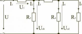
A section of the circuit consists of two series-connected resistances, each of which is equal to 1 ohm. Another resistance is connected in parallel to these two resistors, the value of which is 2 ohms. This entire circuit is connected to a current source, which creates a voltage of 2.4 V at the ends of this connection. Determine the current strength in the entire electrical circuit.
Solution
According to the diagram, the required current strength is the current flowing through the ammeter.
Resistors R1 and R2 are connected in series, resistor R3 is connected in parallel to them.
Resistors 1 and 2 can be replaced with an equivalent resistance R with a prime and redraw the circuit in a simplified form:
Resistances R3 and R with a prime are connected in parallel, you can find the total resistance of the electrical circuit using the formula for a parallel connection:
Now the circuit can be redrawn in an even more simplified form and the current can be calculated using Ohm’s law:
Answer: 2.4 A.
Problem No. 5 on Kirchhoff's law
Kirchhoff's rules are used to calculate complex electrical circuits.
Condition
Three resistances R1 = 5 Ohm, R2 = 1 Ohm, R3 = 3 Ohm and two current sources are connected as shown in the figure. The internal resistances of the current sources can be neglected. The emf of the first current source is 1.4 V, and the current flowing through resistance R3 is equal to I3 = 1 A. Determine the emf of the second current source.
Solution
Let's choose the direction of traversing the circuits clockwise and write down Kirchhoff's law for point A (we will place it between two sources and resistance R2) and two circuits:
Let's substitute the numbers, we get
Solving the system of equations, we get the answer: E2=3.6 V.
Answer: 3.6 V.
Parallel connection
In terms of prevalence, this type of connection is more common than a serial connection. With it, the conductors are connected in such a way that the beginnings of all resistors are brought to one point in the electrical circuit, and the ends to another. In order to replace a branched connection with one equivalent element, you need to know how to correctly calculate the current and voltage.
Let there be a circuit consisting of R1 + R2 + ... +Rn radio elements connected in parallel. A voltage U is applied to it. A current with a force I is supplied to the input of the circuit. Using the law of conservation of charges, the following reasoning can be performed: the current flows into the node to which the beginnings of all resistors are connected, then it spreads across their terminals.
As a result, current I1 will flow through the first branch, I2 through the second, and In into the nth branch. Since the charge cannot disappear, whatever amount of it flows into the node, the same must disperse throughout all branches for the same moment in time. This means that the sum of the currents at all terminals will be equal to the value arriving at them.
The electrostatic field is potential, that is, the work done to move a charge from one point to another does not depend on the trajectory along which the carrier moves. Consequently, when transferring one pendant along any branch, the same amount of work will need to be done. From the above reasoning it follows that with a parallel connection, the formulas with which you can calculate the characteristics of the electrical circuit will be as follows:
- I = I1 + I2 + … +In;
- U1 = U2 = … = Un.
Thus, the calculation of the equivalent resistance, which can replace the entire circuit in accordance with Ohm’s law, is performed using the formula: 1 / R pairs = 1 / R 1 + 1 / R 2 + ... + 1 / Rn. For identical conductors, when calculating resistance, you can use the given formula. This allows in some cases to simplify the calculation.
According to the rule for adding fractions with the same denominator, we can write the equality: 1 / R1 + 1 / R2 + … + 1 / Rn = N / R1. It follows that Rpar = R1 / N, where N is equal to the number of resistors. By analogy, you can calculate the total resistance using a simplified formula for two elements: (1 / R1) + (1 / R2) = (R 2 + R 1) / R 1 * R 2. These are quite convenient formulas for practical use.
Series connection of resistors.
Let's start by looking at circuits whose elements are connected in series . And although we will only consider resistors as circuit elements in this article, the rules regarding voltages and currents for different connections will also be valid for other elements. So, the first circuit that we will disassemble looks like this:
Here we have a classic case of a series connection - two resistors connected in series. But let’s not get ahead of ourselves and calculate the total resistance of the circuit, but first consider all the voltages and currents. So, the first rule is that the currents flowing through all conductors in a series connection are equal to each other:
I = I_1 = I_2
And to determine the total voltage in a series connection, the voltages on the individual elements must be summed up:
U = U_1 + U_2
At the same time, according to Ohm’s law, the following relationships hold true for voltages, resistances and currents in a given circuit:
U_1 = I_1R_1 = IR_1
U_2 = I_2R_2 = IR_2
Then the following expression can be used to calculate the total voltage:
U = U_1 + U_2 = IR_2 + IR_2 = I(R_1 + R_2)
But Ohm’s law is also valid for general voltage:
U = IR_0
Here R_0 is the total resistance of the circuit, which, based on two formulas for the total voltage, is equal to:
R_0 = R_1 + R_2
Thus, when resistors are connected in series, the total resistance of the circuit will be equal to the sum of the resistances of all conductors.
For example, for the following circuit:
The total resistance will be equal to:
R_0 = R_1 + R_2 + R_3 + R_4 + R_5 + R_6 + R_7 + R_8 + R_9 + R_{10}
The number of elements does not matter; the rule by which we determine the total resistance will work in any case. And if in a series connection all resistances are equal (R_1 = R_2 = ... = R), then the total resistance of the circuit will be:
R_0 = nR
In this formula, n is equal to the number of elements. We have sorted out the series connection of resistors, so we logically move on to parallel.