Hello my friend, are you interested to know everything about power balance in AC circuits, then read to the end with inspiration. In order to better understand what the power balance in AC circuits is, the complex power of the source, I strongly recommend reading everything from the category Electrical Engineering, Circuit Design, Analog Devices
Power balance is an expression of the law of conservation of energy in an electrical circuit. The definition of power balance is as follows: the sum of powers consumed by receivers is equal to the sum of powers given by sources. That is, if the EMF source in a circuit supplies 1 W, then the receivers in this circuit consume exactly the same power.
Power balance. From the law of conservation of energy it follows that the sum of instantaneous powers given by all sources of the circuit must be equal to the sum of instantaneous powers consumed by all energy receivers:
where pit is the number of energy sources and receivers in the circuit.
Note. Note that it is not power that is consumed and supplied, but electrical energy.
Equation (2.82) is called the power balance equation (condition).
In sinusoidal current circuits, the balance of complex, active and reactive powers is considered.
The condition for the balance of complex capacities is a relationship similar to (2.82):
For practical calculations, the condition for the balance of complex circuit powers is presented in the following form:
in this case, the terms on the left side of (2.84) are taken with a “plus” sign if the directions of the current Ik and the emf Ek of the voltage source coincide and the direction of the current Jk does not coincide with the direction of the voltage Uk at the terminals of the current source. Otherwise, these terms are taken with a minus sign.
From the condition for the balance of complex powers, the conditions for the balance of active and reactive powers follow:
• the active power supplied by all energy sources is equal to the active power of all its consumers (it is completely consumed in the resistive elements of the circuit):
• the reactive power of all sources is equal to the reactive power of all consumers (it circulates between energy sources and its consumers):
where Rk and jXk = jXLk - jXCk are the real and imaginary parts of the complex resistance of a passive element.
Power balance for DC -
Or
Definition
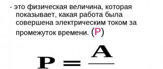
The calculation of this parameter in an electrical circuit is based on the well-known law of conservation of energy. It follows from this that the instantaneous indicators transmitted from the source must be equal to the sum of the values received by consumers.
The balance for power is the well-known law of conservation of energy. The expression of this law in this case is the sum of all energy from the sources (generator or power supply) equals the amount received by the receivers.
An alternative option can be used. For it, the formula looks like the figure below:
It is worth taking into account that any electrical circuit has resistance. The described value with accompanying values is calculated taking into account the type of stress. Taking into account the law of conservation of energy, it is worth considering that energy is always transferred through an electrical circuit.
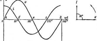
Power factor
It is energetically beneficial to operate a generator or electrical equipment if it performs maximum work. The website https://intellect.icu talks about this. Work in an electrical circuit is determined by active power P. Power factor shows how efficiently a generator or electrical equipment is used λ=P/S=cosφ≤1 As the power factor decreases, the cost of consumed electricity increases. Ways to increase power factor Power is maximum when P = S, i.e. in the case of a resistive circuit. The generator carries out only irreversible energy conversions and does not participate in oscillatory processes of energy exchange with the electromagnetic field of receivers in maximum power mode. Consumers of electrical energy mainly have an equivalent circuit of the RL element, so increasing the power factor is possible by compensating reactive power by connecting a capacitive element (QL-QC), connecting a capacitive element reduces the current in the power line, which makes it possible to reduce the cross-section of electrical wires, and this leads to savings electrically conductive materials. The value of power factor in power systems depends on how competently electrical installations and devices are operated. cosφ may decrease if the units are idling or underloaded
When solving electrical problems, you often need to check the correctness of the found values. For this purpose, in the science of TOE, there is a so-called power balance.
Let the EMF source be loaded with resistance
(Fig. 3.25).
Rice. 3.25
The magnitude of the current in the circuit is known. Let us consider the so-called conjugate current complex , whose argument (initial phase) has the opposite sign compared to the argument of the initial current.
Let us denote the complex power of the source . Let's expand on the last expression:
(3.27)
Thus, the active power of the source is equal to the real part of the complex power,
and reactive power is the imaginary part.
The active power of receivers can be written using complex effective values of currents and complex resistances as , and reactive power - .
Mathematically, the balance of active and reactive powers in a complex form can be represented in one expression. So, for a circuit with sources of emf and current it has the form
,
or
. (3.28)
Rice. 3.26
Let's make a diagram for the circuit. 3.26 power balance in complex form:
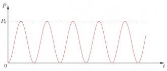
Alternating current
The power balance in a simple AC circuit is calculated using a more complex formula. Power balance in a simple sinusoidal current circuit takes into account complex, reactive and active parameters.
- Comprehensive. Consists of transmitted and received powers. It will be necessary to perform a calculation in which all terms on the left side of the formula are positive (come with + signs), provided that the direction of the charged particles “Ik” coincides with the “EMF”. The rule that “Jk” does not coincide with the direction of voltage “Uk” must be observed. If the conditions do not meet the specified requirements, all data on the left side of the formula becomes negative. The formula is given below.
- Active. The values given by the source are equal to those received by consumers. The calculation of active power is entirely dependent on the presented complex energy. The active value is consumable, non-renewable, as it is spent on the operation of devices. This calculation method and its formula are presented below.
- The reactive power of the source and the consumer are equal. The only difference is that this parameter is not wasted. This indicator simply circulates according to the scheme. The formula is presented below.
The main difference between the quantity under consideration is the presence of non-directional movement of alternating current through the conductors. The parameter of such a circuit can be increased or decreased (for example, by a generator), which can affect the final result.
Power and Energy Balance - Power System Wiki
Balance of power and energy
is calculated to determine the possibility of covering the load schedule and identifying the need to introduce new energy sources.
General provisions
The frequency of alternating current in the electrical network and the voltage at the nodes are the most important indicators of power quality. What these indicators have in common is that they are both related to power balances in the power system.
The frequency value at any time during normal operation is the same in all nodes of the electrical network. At the same time, voltage levels at different points of the network can vary greatly and at the same time in some nodes they comply, but in others they do not comply with the requirements of GOST and technological connection agreements. In this sense, voltage, as a power quality parameter, must be analyzed in each individual node of the power system.
Each moment of steady state in the electric power system corresponds to balances of active and reactive powers. The power balance equations can be written as:
; ,
where and are the total active and reactive powers of generating sources; and - total active and reactive powers of loads; and - total power losses in the elements of power supply systems and the electric power system; and — total power consumption for the power plants’ own needs; — total powers of compensating devices (the “+” sign corresponds to devices consuming reactive power, the “-” sign to generating ones); total reactive (charging) power generated by overhead power lines.
Sources of active and reactive power are generators of power plants: thermal, nuclear, hydraulic, combined cycle and gas turbine, in addition, sources of active power can be generating electrical installations of non-traditional energy sources (wind, tidal and geothermal stations, solar panels). Depending on the type and design, some non-traditional active energy sources consume reactive energy. While for synchronous generators of power plants, the reactive power consumption mode can only be short-term in emergency situations.
D.C
In a DC electrical circuit, voltage and power are always the same value. Therefore, the calculation is much simpler. You can make a calculation based on a fairly simple example.
- There is an emf “E” and a resistor “R” in the circuit. When calculating, the current strength must be found.
- I=E/R. We substitute the available values, we get I=10/10=1 ampere.
- This is how we found the current strength. Now we will need the power parameter of the receiver “R” and the source.
- Pist=I×E=1×10=10 Watt. This is the value for the source.
- Now, in order to find P for the receiver, we do the calculation as in the figure below.
- Now let's create a total balance - 10 watts = 10 watts. This calculation showed that equilibrium is maintained for the presented scheme.
When calculating the parameters of this circuit, it makes sense to take into account the receiver flow rate. When heated, the resistor releases heat, which means that electricity is converted into heat. Taking into account the physical law of conservation, the heat generated by the resistor will also be equal to 10 Watts.
Drawing up a power balance
From the law of conservation of energy it follows that all the power supplied to the circuit from energy sources at any time is equal to all the power consumed by the receivers of the given circuit.
That is, IPconsumption = Psource.
The power of consumers, which are resistors in DC circuits, is determined by the formula
Pconsumption = I2R
Since the current is included in this expression squared, regardless of its direction, the power consumption is always positive.
The power of sources, which can be voltage sources and current sources, can be both positive and negative.
Source power emf. determined by the formula
A)
Pe.m.f.= EI
where I is the current in the branch with the emf source.
b)
If e.m.f. and the current of this branch coincide in direction (Fig. 19a), then the power P.m.f.
is included in the balance expression with the “+” sign,
if they do not coincide, then P.e.m.f. is the value
Fig. 19 negative.
The power of the current source is determined by the formula:
P.t.= IU
Where I is the value of the source current, U is the voltage at its terminals.
If the current I and voltage U act as shown in Fig. 19b, then the power is positive; otherwise it is negative. Consequently, when calculating the power of a current source, it is necessary to determine the magnitude and direction of the voltage at its terminals.
Task:
Control questions:
- What is an electrical diagram? What refers to the “electrical” and “geometric” elements of the circuit.
- Define serial and parallel connections of circuit elements.
- The concept of “circuit” in an electrical circuit.
- What is the difference between an active branch and a passive branch?
- Potential diagram, its purpose.
- State the rule for choosing signs when finding the potentials of points.
- Formulate a generalized Ohm's law. What is the scope of its application?
- Formulate Kirchhoff's first law. How to determine the number of nodal equations? Rule of signs when writing a nodal equation.
- Formulation of Kirchhoff's second law. How to determine the number of contour equations. Rule of signs when writing a contour equation.
- What is meant by power balance? How is the power of a voltage source, current source, or receiver determined?
- The power of which elements (active or passive) can be negative and what does this mean?