Quartz resonators are passive components of electronic equipment and are intended for use in analog-digital circuits to stabilize and isolate electrical oscillations of a certain frequency or frequency band. The operating principle of this element is as follows: over a wide frequency band, the resistance of the device is capacitive in nature and only at some (operating) frequencies does it have a pronounced resonance (resistance decrease).
A quartz resonator has better characteristics than other devices for frequency stabilization (oscillatory circuits, piezoceramic resonators): such as stability in frequency (frequency drift) and temperature (change in resonance frequency depending on the ambient temperature).
The selective, pronounced resonant nature of the resistance of these components determines the main areas of application of quartz resonators - highly stable generators of clock signals and reference frequencies, frequency selection circuits, frequency synthesizers, etc.
Imported quartz resonators
| Currently available quartz resonators in housings of the following types: |
- HC-49/U - the closest domestic analogue - MD hull
- HC-49/US - difference from HC-49/U - lower height
- Quartz resonators for timing circuits at a frequency of 32.768 kHz
Components are certified in accordance with the international standard ISO 9002
Distinctive features:
- Low cost
- Industry standard
- Wide frequency range
- Low variation in operating frequency over time
- AT resonators
Appearance of HC-49 type housings Main technical characteristics:
| Parameter | Frame | Magnitude | Generation conditions | Dimensional drawing |
| frequency range | HC-49/U | 1.8 - 30 MHz | Fundamental harmonic |
| Housing | L, mm |
| HC-49/U | 13,0±0,2 |
| HC-49/US | 3,5 |
Technical parameters of quartz resonators:
- The AT resonator type is a special cut angle of the quartz crystal plate, at which the finished resonator has excellent frequency stability with respect to ambient temperature.
- Series equivalent resistance is the impedance of a resonator in series resonance.
- Frequency stability - frequency deviation from the nominal one. Usually expressed in parts per million of the nominal frequency of the resonator - Nx10 -6. The corresponding foreign marking is ppm (part per million).
- Temperature stability of frequency - change in frequency when the temperature of the resonator changes.
- Insulation resistance - resistance between the terminals of the resonator (usual values are on the order of MΩ)
- Load capacitance - any external capacitance connected in series with the resonator becomes an element that changes the resonance frequency. By varying the load capacitance, it is possible, within certain limits, to change the resonant frequency. Some manufacturers sometimes recommend in advance the use of standard load capacitance values to fine-tune the resonant frequency.
- Operating temperature range - the temperature range in which the resonator will operate with a frequency deviation not exceeding that specified for this type.
- Harmonics - for resonators with the AT cut type, which themselves are resonators of thickness-shear oscillations, in addition to the main resonance frequency, oscillations of odd harmonics (3xFmain, 5xFmain, 7xFmain) are also possible.
- “Aging” is a slow change in the parameters of the resonator after a certain period of time.
Standard frequency grid values for imported resonators, offered by Promelektronika JSC
The most common types of sealed quartz resonators in a metal case were produced in the USSR according to GOST 6503-67 “Sealed quartz resonators for oscillation frequencies from 0.75 to 100 MHz.”
According to this standard, resonators of the class under consideration must be produced in miniature (for the range from 5 to 100 MHz) and small-sized (for the entire frequency range).
They can be made with hard leads for insertion into the panel (see, for example, RKM-3), with soft leads for direct soldering in the circuit, and with hard tinned leads for soldering installation wires to them.
Properties of a quartz resonator
The crystalline element of the piezoelectric resonator enters a state of resonance, and the mechanical stresses operating within it undergo the most dramatic changes in magnitude and phase with relatively small variations in the oscillation frequency; the total electrical resistance of the system changes in a similar way. When using this phenomenon, a piezoelectric crystal is placed in a high-frequency electric field, for example between two metal electrodes, secured in a certain way (mechanically) so that the location of all elements of the device remains unchanged during operation.
Various quartz resonators.
The mechanical system in which the quartz element is fixed and which carries the structural elements necessary to excite the quartz is called a crystal holder. If an alternating electrical voltage is applied to the electrodes between which the quartz element is placed, then the mechanical stresses and deformations in the crystal will also be variable, and at a frequency of the alternating electrical voltage equal to the frequency of the natural mechanical vibrations of the quartz, mechanical resonance occurs. In this case, alternating charges appear on the faces of the quartz element, and consequently on the electrodes of the crystal holder, the magnitude and phase of which are determined by the complex amplitude of the mechanical stresses in the crystal. The full table of frequencies of quartz resonators is presented in the table below (clickable to enlarge).
Table of frequencies of quartz resonators.
The interaction of these charges with charges created by an externally applied alternating electric field changes the relationship between the voltage on the electrodes of the crystal holder with quartz and the current through it, and the electrical resistance of the system to alternating current changes with the frequency of the latter.
The presence of direct and inverse piezoelectric effects allows us to consider quartz resonance either as a phenomenon of mechanical vibrations of an elastic solid, acting due to the piezoelectric effect on an electric field, or as a phenomenon of electrical vibrations of some electrical circuit equivalent to a quartz resonator. Both methods of consideration lead to the same result: the parameters of the electrical equivalent circuit can be expressed in terms of the physical constants of the crystal and through the electrical connection between the quartz element and the holder.
Typically, a quartz resonator, which is a piezoelectric crystal fixed in a holder, is part of some external electrical circuit that performs certain functions in a particular radio device designed to solve a specific technical problem. Naturally, only the second way of considering a quartz resonator can satisfy practical requirements, therefore, knowledge of the equivalent electrical circuit that replaces the element and crystal holder, its shape and parameters is a very important task for practice. If the equivalent electrical circuit in its form, parameters and application limits is determined so that it quite strictly (with the specified limitations) reflects the phenomena occurring in an oscillating piezoquartz, then this allows us to consider the theoretical issues of a quartz resonator as an element of an external electrical circuit in isolation from the crystal itself and solve technical problems in which piezoquartz is used using conventional methods applicable to linear electrical circuits.
Material on the topic: all about the variable capacitor.
Depending on the purpose, a quartz resonator is made in various ways. When used as a resonant oscillating circuit in a generator, it must be designed for a certain dissipation power. When used in filters and to control the frequency of radio transmitting devices, it is not the dissipation power that is essential, but the minimum attenuation, low coupling with the external circuit, etc. Therefore, the dimensions of the quartz elements, their shape, the harmonic number, as well as the design of the crystal holder in these cases are different .
It will be interesting➡ Designation of chokes on the diagram
For different types of quartz resonators, the parameters of the equivalent electrical circuit vary in magnitude, although the shape of the equivalent circuit remains unchanged. The simplest equivalent circuit looks like in the case of quartz elements, onto the surface of which metal films—electrodes—are directly deposited by vacuum sputtering; somewhat more complicated - in the case of quartz elements placed between electrodes with gaps, or in the case of a quartz filter having two input and two output electrodes.
Dimensions of the quartz resonator.
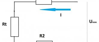
From the point of view of external electrical circuits, using dynamic analogies, a quartz resonator can be replaced by an equivalent electrical oscillatory circuit. In mathematical calculations, considering an equivalent electrical circuit (instead of a quartz resonator in an oscillating state) allows us to abstract from the quartz resonator as an electromechanical oscillatory system and consider it as an element of an electrical circuit.
The equivalent electrical circuit of a quartz resonator consists of active resistance R1, capacitance C1, and inductance L1, connected in series and shunted by parallel capacitance C0. The parameters R1, C1, L1 are the main ones and are called the dynamic parameters of the piezoelectric resonator, the parameter C0 is the static capacitance. If a quartz element is excited in a crystal holder with gaps, then parameter C3 is added to its equivalent electrical circuit - the capacitance of the crystal holder gap.
An equivalent resonator circuit is an equivalent circuit for replacing an electromechanical oscillatory system with one degree of freedom with an equivalent electrical oscillatory circuit
.
Varistor selection
To effectively and reliably protect your equipment, you need to choose a varistor wisely. As a rule, to protect household appliances, varistors with a threshold voltage value from 275 to 430 V are used. We will not go into particular detail in the selection of varistors taking into account other values (capacitance, etc.). There are many nuances here that simply cannot be considered in the format of this article. For a more accurate selection of a varistor, we can recommend using reference books on varistors. They indicate all the characteristics that a particular varistor has. This will allow you to choose the most suitable one for your goals and objectives.
Another important parameter when choosing a varistor is the response speed. As a rule, for most varistors it is about 25 ns. But this is not always enough.
Then varistors with shorter response times are suitable for you. An unattainable ideal in terms of response speed are varistors manufactured using the SIOV-CN multilayer structure technology. Their response speed can be less than 1 ns.
Such varistors are necessary for protection against static electricity. In household appliances, such varistors are practically not used.
Have you probably heard about cases when many people’s electronics burned out at once? This happens precisely due to the fact that only the phase goes through the wires. A varistor also protects against this.
Parameters of quartz resonators
Rated frequency – frequency Fn indicated on the marking or in the documentation for the quartz resonator (measured in MHz or kHz). Base frequency is the real frequency of the resonator Fo, measured under given operating conditions. As a rule, only climatic conditions are determined, namely the base ambient temperature To (equal to 25 ± 2 ° C for resonators with a cutoff type AT). Operating frequency – the real frequency of the resonator F, measured under real operating conditions (climatic, mechanical and electrical). Typically, only the permissible operating temperature range is defined.
It will be interesting➡ Varistors - what they are, operating principle, characteristics and parameters.
Frequency setting accuracy is the maximum permissible relative deviation of the base frequency of the resonator from the nominal frequency. It is measured in parts per million of the nominal frequency, designated as ppm (part per m illion) or 1•10 -6. In some rare cases, the value of this parameter is given as a percentage. As a rule, the accuracy value for tuning the frequency of a quartz resonator is selected from the standard range.
Parameters of quartz resonators.
Temperature frequency instability
Relative deviation of the resonator operating frequency from the base frequency. Can be presented as a function of operating temperature T, in accordance with the formula for quartz plates with the AT cut type and formula (4) for quartz plates of other types. Long-term frequency instability (aging) is a systematic change in the base frequency over time due to internal changes in the quartz resonator. The aging parameter is specified as a relative change in the base frequency over a given period of time. This value is expressed in parts per million per year (for example, 3 ppm/year). Frequency drift under the influence of aging is most noticeable during the first 30–60 days of operation, after which the influence of this factor decreases. The standard range of relative frequency deviations for general purpose resonators includes the following accuracy classes: ±5, ±10, ±15, ±20, ±30, ±50, ±75 and ±100 ppm.
Material on the topic: the device of a trimming resistor.
Resonator operating mode (harmonic number)
The operating mode of the resonator is an unchangeable parameter that determines the oscillation frequency. For quartz crystals, not only the fundamental frequency can be used, but also its odd harmonics - overtones. For example, a crystal may operate at a fundamental frequency of 10 MHz, or at odd harmonics of approximately 30 MHz (third overtone), 50 MHz (fifth overtone), and 70 MHz (seventh overtone).
Studying a simple circuit
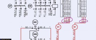
Okay, let's get to the point. Let's look at a simple electrical circuit of a power supply, which used to appear in any Soviet paper publication:
If this is not the first day you have held a soldering iron in your hands, then everything will immediately become clear to you at first glance. But among my readers there are also those who are encountering such drawings for the first time. Therefore, this article is mainly for them.
Well, let's analyze it.
Basically, all diagrams are read from left to right, just like you read a book. Any different circuit can be represented as a separate block to which we supply something and from which we remove something. Here we have a circuit of a power supply to which we supply 220 Volts from the outlet of your house, and a constant voltage comes out of our unit. That is, you must understand what main function your circuit performs. You can read this in the description for it.
Temperature settings
Base temperature - Ambient temperature That, for most resonators, is equal to 25 ± 2 ° C, at which measurements of certain parameters of a quartz resonator are performed (in particular, the value of the base frequency). Operating temperature range - The temperature range for which the manufacturer guarantees that the maximum deviation of the operating frequency from the nominal value does not exceed the specified tolerance. The temperature range in which the resonator remains operational, but the frequency deviation from the nominal value may exceed the limits guaranteed by the manufacturer.
Storage Temperature Range – The temperature range over which the quartz crystal can be in storage mode (i.e., not oscillating). After storing the resonator and ensuring the temperature is within the operating range (for a certain period of time), the resonator can be used in oscillation mode, and all parameters specified by the manufacturer will be guaranteed.
Checking the resonator.
About device details
Part of the board is assembled on lead parts, and part on SMD. The board is designed for the Winstar single-line LCD indicator WH1601A (this is the one with the contacts at the top left), contacts 15 and 16, which serve for illumination, are not wired, but anyone who needs can add tracks and details for themselves. I didn’t turn on the backlight because I used a non-backlit indicator from some phone on the same controller, but at first there was a Winstar one. In addition to WH1601A, you can use WH1602B - two-line, but the second line will not be used. Instead of a transistor in the circuit, you can use any of the same conductivity, preferably with a larger h21. The board has two power inputs, one from a mini USB, the other through a bridge and 7805. There is also space for a stabilizer in another case.
Electrical parameters
Equivalent circuit of a quartz resonator is an electrical description of a quartz resonator operating at a resonant frequency. The equivalent circuit of a quartz resonator is shown in Figure 1. C0 is the shunt capacitance. R1, L1 and C1 are dynamic resistance, dynamic inductance and dynamic capacitance, respectively. The dynamic parameters are the corresponding equivalents of the resonator as an electromechanical system and are determined mainly by the cutoff characteristics of the quartz element.
It will be interesting➡ What is an inductor and why is it sometimes called a choke
Shunt capacitance C0 – Capacitance between the terminals of the crystal. It is measured in picofarads. The shunt capacitance consists of the parasitic capacitance of the quartz, the capacitance of the crystal electrode region, and the capacitance contributed by the crystal holder. The shunt capacitance has a value of the order of units of pF. Dynamic resistance R1 – Parameter characterizing energy losses in the oscillatory circuit. The dynamic resistance R1 of quartz resonators varies in the range from several Ohms to hundreds of kOhms, depending on the resonance frequency, harmonic number and a number of design factors.
Set of quartz resonators.
Varistor marking
If your varistor is faulty, then knowing the varistor markings will be of great help to replace it. The marking itself is located on the case and is a set of Latin letters and numbers. Despite different manufacturers, for the most part, the markings on varistors are not very different and are quite easy to read.
As an example, here are 2 different varistors from different manufacturers:
- CNR-12D182K
- ZNR V12182U.
The first number 12 indicates the diameter of the varistor in millimeters. The second number is 182K opening voltage. 18 – voltage, 2 – coefficient. CNR is the designation of the varistor material. In this particular example, the varistor is made of metal oxides.
K – used to indicate the accuracy class. That is, if it is written on the varistor body - 275K, then K is the accuracy of 10%, and 275 is the opening voltage. And the opening voltage is calculated as follows - 275 + - 27.5. That is, for example, our 20D471K varistor can be replaced with a TVR20471 varistor. Or any other analogue of a varistor. For example – SAS471D20. You just need to know the basic principles of labeling.
True, this will not work with domestic varistors. You will have to use reference materials. Our varistors are designated as follows: CH2-1, VR-1 and CH2-2. For example: CH-2 – zinc oxide varistors. But this can only be found out from reference materials.
Despite the labeling principles described above, we strongly recommend using reference literature when choosing a varistor. It indicates all the necessary characteristics of the varistor, including those that cannot be recognized by the markings.
What to do if the markings on your varistor are erased?
A megohmmeter will help you find out what voltage your varistor is designed for. To check the varistor, you need to connect it to a megger and run it within the limits. That is, if the varistor is 470V, then it should be checked at 500V.
There is a way using a power supply. True, this requires a power supply with adjustable voltage and maximum current. The current strength must be set so that the varistor does not burn out. And as we wrote above, they tend to explode.
Varistor with erased markings
Accordingly, it should be visually inspected before connecting. If there are cracks, swellings on the varistor body, and it is visually clear that it has melted, then such a varistor is definitely not working. But often these are cracks. The material of varistors is prone to aging, this should always be kept in mind. Varistors with such damage may not be checked. They are not workers.
More details about varistors in the video:
Load capacity CL
The measured or calculated value of the capacitance connected in parallel with the quartz resonator. The resonant frequency of quartz included in a real electrical circuit will vary within certain limits at different values of load capacitance. To simplify the interaction between customers and resonator manufacturers, it is practiced to configure resonators at a certain value of the load capacitance. In this case, the measured frequency must correspond to the nominal one, taking into account the specified tuning accuracy.
As a rule, to match the load capacitance, capacitors Cg are used, connected between the terminals of the quartz resonator and the common wire (Figure 2). Calculation of the capacitance rating of capacitors Cg is carried out according to formula (6), where CL is the load capacitance specified in the technical documentation, and CS is the value of parasitic capacitance (approximately 5 pF).
For example, for a load capacitance of 16 pF we have:
Cg = 2·(16-5) = 22 pF
Typically defined as the power dissipated by a quartz crystal. The minimum value of this parameter is determined by the amount of energy required to normally start the resonator and ensure stable oscillations. However, an increased value of this parameter can cause deterioration of aging parameters and mechanical damage to the crystal.
Modern and outdated resonators.
Quartz housings in SMD version
| Standard size | A | B | C | D | E |
| SX3225 | 3.5 mm | 2.2 mm | 1.2 mm | 1.6 mm | 0.7mm |
| 5032 (MJ) | 5.0 mm | 3.2 mm | 2.6 mm | 2.3 mm | 0.8 mm |
| 7050 (MQ) | 7.0 mm | 5.0 mm | 4.6 mm | 2.5 mm | 1.3 mm |
Piezoelectrics
In fact, quartz is one of the most common minerals in the earth's crust. Its share is about 60%! If semiconductor radio components are mainly made of silicon, then quartz also consists of silicon but combined with oxygen. Its chemical formula is SiO2.
The mineral quartz looks something like this.
mineral quartz
Well, just like some kind of treasure! But the value of this treasure is hidden not in the quartz itself, but in the properties it has. And this quartz effect has revolutionized precision electronics for generating highly stable electrical signal oscillations.
Back in the 19th century, the two Curie brothers discovered the interesting property of some solid crystals to generate emf by deforming these crystals. Deformation is a change in the shape of a body through torsion, impact, stretching, and so on. So, when they hit such crystals, they discovered that they could produce some kind of short-term voltage.
piezoelectric effect
But they also found the opposite effect. When voltage was applied to such crystals, these crystals themselves deformed. It was practically invisible to the naked eye. This effect was called the piezoelectric effect, and the substances were called piezoelectrics.
It should be noted that EMF occurs only during compression or tension. Maybe you thought that you could press such a crystal with some heavy block and receive energy from it all your life? No matter how it is! By the way, a radio element, a piezoelectric emitter, also belongs to piezoelectrics, and EMF can be obtained from it. Below you can see this case in the video. An LED soldered to the piezo emitter lights up when the piezo emitter itself is struck.
Not long ago I watched a film on National Geographic. There, entire piezoelectric plates were installed on the road. People walked on them and generated electrical energy without knowing it). By the way, very free, clean and renewable energy. Okay, I got distracted... So, quartz crystals also have a piezoelectric effect and are also capable of generating EMF or deforming (bending, changing shape) under the influence of electric current.