It happens that it becomes necessary to turn on the PSU (power supply) of the computer without the participation of the computer itself, or more precisely, without connecting to the motherboard.
Basically, this need arises when, for example, it is necessary to check the health of the power supply or in order to power some device with a voltage of 5 V or 12 V.
I once had to use an ATX power supply as a power supply for my D-Link modem.
You can also use the ATX unit as a power supply for an old radio and for much more.
Turning on the power supply without load
I will describe two options.
First way
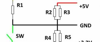
In order to start the ATX unit, you simply need to short-circuit the green and any black wires on the power supply connector (PS-ON and GND pins, respectively, see the figure below).
This is what it looks like in real life:
It also happens that on some power supplies these wires may be of different colors (you understand - the Chinese), so I recommend taking a closer look at which wire you have as the PS-ON output.
Second way
If you don’t have a piece of wiring at hand, then the same steps can be done using a regular paper clip
. We close all the same colors of wires.
Checking the power supply without connecting to a computer
First of all, you need to conduct an external inspection for damage to both the power supply housing itself and the cables. When the power supply is connected to the network and the switch on the rear panel of the unit is in the correct position (on), a standby voltage of 5 V should appear on the 24-pin connector. The permissible deviation from the nominal value is ± 5%, that is, from 4.75 V to 5 .25 V.
The standby voltage is supplied to the motherboard and allows its logic to signal the power supply to turn on. That is, when we press a button on the system unit, we send a signal to the motherboard, and it then signals the power supply that it would be nice to start. You can measure it here:
If it is not there, check the condition of the power cable, the presence of voltage in the network and the position of the switch on the rear panel of the unit. Everything is correct, but there is no tension? Check again whether you are taking measurements on the right contact, and if everything is done correctly, but there is no voltage, most likely the power supply is faulty. Failure of the standby power supply is not such a rare cause of failure.
If there is standby voltage, as in the picture above, then you can start the power supply by closing two contacts on the 24-pin connector block. In this case, we need PS_ON and any ground contact. It’s convenient to do this with a regular paper clip if you bend it the right way, but any piece of wire will do.
This operation must be done carefully. Although, when the unit is not running, but is turned on, we only have voltage on a couple of contacts - the standby voltage source and PS_ON, and if you close them somewhere in the wrong place, nothing bad will happen. Modern power supplies, as a rule, have protection against short circuits on the standby power source.
The power supply should start and the fan should spin up, if it operates at low loads at all, that is, you do not have a power supply with semi-passive cooling. Now you can measure the main voltages. There are three of them: 3.3 V; 5 V and 12 V. There is also a voltage of -12 V, but it can be ignored. In modern systems it is not needed. First of all, where to measure. The most accessible connectors in this case are four-pin Molex.
Previously, all ATX power supplies had wires of a certain color for each voltage, and there were explanations about this for a couple of pages in the Power Supply Design Guide, but recently black wires have become fashionable. Yes, they definitely look more aesthetically pleasing, but it has become more difficult to navigate where what voltage is on the connector. That's why I made a couple of pictures with pinouts for you. It is convenient to navigate which side of the connector is by using the latch.
Connector for additional power supply for video cards.
CPU power connector.
The 3.3V voltage is only available on the 24-pin connector.
Basic voltage tolerances ± 5% of nominal.
We measure all voltages, and if they are within acceptable limits, the power supply can be considered conditionally serviceable. Why conditional? Complete information about its condition can only be obtained by testing under load.
Why can't you turn on a computer power supply without a load?
Now a few precautions.
If you don't do this, the voltage conversion circuit may fail and require expensive repairs to the ATX power supply.
, and maybe its complete replacement due to the economic irrationality of repairs.
By the way, it happens that some power supplies simply may not start without load.
For many fairly experienced users of personal computers, it is no secret that any power supply without a motherboard by connecting certain contacts on the main 20/24 pin chip.
Such a need may arise when you need to check the performance of a unit in which the system unit does not respond to pressing the power button. After all, he is the first suspect in such cases.
In this article we will tell you which wires need to be closed in order for the computer power supply to start.
Checking using special programs
You can also check the power supply using special test programs. One of them is OSST Perestroika. You can download it for free on the official website of the developers at: https://www.occt.ru/download.
To check you will need:
- run the utility;
- click on the gear image;
Click on the gear image - set in the window that opens the temperatures at which the test will be stopped;
In the window that opens, set the temperatures at which the test will be stopped - go to the “Power supply” tab;
Go to the “Power supply” tab, press the “ON” button - run the test and see what voltage the power supply produces.
We monitor the testing process and study the data
Important! Remember that it is better not to check the power supply using the Perestroika OSST for malfunctions. This software heavily loads the computer hardware, and it, in turn, heavily loads the power supply. Therefore, if you believe that the block is on the verge of “death”, it is better not to put it at risk. The program is not intended to detect failures, but to test the performance and stability of the system.
In addition, you can test the power supply using other programs, for example, AIDA64. This program also puts a very heavy load on all computer components during testing, so testing must be approached responsibly and carried out with caution.
Which contacts should be closed to start the power supply?
If you need to find out the performance of a block, then the best way to do this is to force it to start. Despite the fact that in cases where there is no reaction to pressing the power button of the system unit, the power button and even the motherboard may be the culprits.
So, first we completely de-energize the block. That is, we pull out the wire going into the socket. After this, take a piece of wire or a paper clip.
The green wire is the starting wire. It must be connected with any black one.
This is what it looks like in the diagram:
Pinout of the 20 pin power supply connector
After the contacts are closed, you can plug the power cord into the outlet. Please note that if there is a button on the back wall, it must also be turned on.
Breakdowns and malfunctions in the operation of a computer are an integral part of the process of operating the device. Failures (damage) can be software or hardware. Software problems are related directly to the software, while hardware problems imply a breakdown of the physical components of the computer system. Both groups of breakdowns require immediate and competent intervention from a specialist.
A computer power supply (or Power Supply) is a minor element of a computer system that is necessary to fill the computer components with a direct current energy flow. Explained in simple terms, Power Supply is the source of electrical power for a computer.
The need to connect PS without auxiliary elements arises in such cases:
- The need to diagnose the operation of the device.
- In the process of renovation.
- When using multiple power supplies in one computer case.
- Diagnostics of the performance of new circuits.
Main symptoms and malfunctions
A faulty power supply, most often simply does not work at all. But sometimes, the user encounters problems that, by all indications, are manifestations of problems in the RAM or motherboard. In fact, the microcircuits receive power from the power supply, so failures in their operation may indicate a malfunction of the power supply. How to check the power supply in this case, and whether there is any point in repairing it, only a specialist can tell. Next, problems will be described in which the cause may be BP.
- Freezes when turning on the PC.
- Sudden system reboot.
- Memory errors.
- Stop HDD.
- Stopping the fans.
The power supply is outside the computer case. There are also characteristic faults that the PC itself “speaks” about:
- Not a single device works. The malfunction can be either fatal, requiring the purchase of a new device, or simple, requiring replacement of the fuse.
- There was a smell of smoke. The transformer, chokes burned out, and the capacitors swelled.
- The computer power supply is beeping. The fan may need to be cleaned and lubricated. A squeak when turned on is also caused by a crack in the transformer core and swelling capacitors.
In all cases, it is best to contact a service company in your city, where specialists will make a more accurate diagnosis and tell you whether there is any point in further repairing the device.
Power unit. General information. Standard power supply startup
Using an electrical power supply helps protect your computer from frequent power outages. A mandatory element that comes with the Power Supply is a fan (other names: cooler, cooler). It constantly cools the PS and protects it from overheating, which can lead to breakdown.
The standard process of turning on Power Supply involves pressing the “Start” button on the motherboard, which activates the process of powering the unit. There is a widespread belief that it is impossible to turn on a power supply without a motherboard, because it does not start without voltage, but this is just a misconception.
If when you press the computer's power button it does not turn on and does not react in any way, then we can assume that the motherboard is most likely faulty or the Power Supply is broken. Before buying new expensive components, you should diagnose the operation of existing ones.
Paperclip method
There is a simple method among users to check the power supply with a paper clip. Our resource will not stand aside and will tell you what this method is, especially since almost the same thing was discussed in the section on using a multimeter. This is the simplest, one might say, home method, which cannot show the quality of operation of the voltage source, but will reliably make it clear whether it turns on or not.
- Disconnect your PC from the network.
- Open the case and disconnect the connector from the motherboard.
- Make a U-shaped jumper from a paper clip, which you need to short-circuit the green wire of the connector and the nearby black one.
- Connect the power supply to a 220 V network.
If the fan starts working, then the power supply is theoretically in working order, if not, it’s definitely in repair.
How to turn on the power supply without a computer
To turn on the power supply without a computer, you should pay attention to the tables of the locations of all the necessary contacts on the connector. The pins of a standard ATX block are presented in the table below:
| Color | Signal | Contact | Contact | Signal | Color |
| Orange | +3.3V | 1 | 13 | +3.3V | Orange |
| +3.3V sense | Brown | ||||
| Orange | +3.3V | 2 | 14 | -12 V | Blue |
| Black | Earth | 3 | 15 | Earth | Black |
| Red | +5V | 4 | 16 | Power on | Green |
| Black | Earth | 5 | 17 | Earth | Black |
| Red | +5V | 6 | 18 | Earth | Black |
| Black | Earth | 7 | 19 | Earth | Black |
| Grey | Power good | 8 | 20 | -5V | White |
| Violet | +5 VSB | 9 | 21 | +5V | Red |
| Yellow | +12 V | 10 | 22 | +5V | Red |
| Yellow | +12 V | 11 | 23 | +5V | Red |
| Orange | +3.3V | 12 | 24 | Earth | Black |
- The three shaded pins (8, 13 and 16) are control signals, not power.
- “Power On” is pulled up by a resistor to +5 Volts inside the power supply, and must be low to turn on the power.
- “Power good” is kept at a low level while the voltage at the required level has not yet been generated at the other outputs.
- The “+3.3V sense” wire is used for remote sensing.
Before you learn how to turn on a power supply without a computer, follow these tips: do not start the power supply without supplying at least some load. The circuit that converts electricity may break and then the ATX unit will need to be replaced. Such repairs can be quite expensive.
How to start a power supply without a motherboard:
- Close the Power On contact to zero. In almost all cases it is colored green.
- Short the ground - any contact painted black. It is enough to close just one. Closed contacts look like this:
- If you are using a pin table, then take a simple paperclip and touch it to pins 15 and 16. In this simple way you will close them. The table above will help you navigate the ATX power supply pins. Once the required contacts have been closed, Power Supply should start. If this does not happen, then you can short the green wire and the other black one.
- Try not to overload the Power Supply as much as possible. Connect to it, for example, a hard drive or floppy drive.
Chinese block manufacturers often confuse the English color names gray and green, so the green wire may be gray. In any case, try to navigate according to the table.
Replacing an ATX power supply is expected in the event of a breakdown of the old copy or in the case when the constituent elements of a personal computer have been replaced: more powerful video cards, processors, motherboards, more RAM. In the case of such a PC upgrade, the power supply becomes unable to supply power to all components of the PC. First of all, you need to remove the existing ATX element, install a new one and test its performance. You just need to know the basic concepts of circuit design and follow the instructions below:
- Necessary tools: standard size Phillips screwdriver.
- It is necessary to turn off the power to the personal computer - this process involves unplugging the power cord from the power supply.
- The next step is to remove the wall of the system unit; it is usually removed from the left side of the case by unscrewing several screws.
- Remove all accumulated dust from the computer components with a brush or vacuum cleaner. Please note that you need to clean your computer from accumulated dust at least once every six months
. Only after complete cleansing of dust can you proceed to the next steps.
- Disconnect all wires belonging to the power supply from other devices. Pay attention to the possible presence of special latches in the connectors. Do not pull out the connected wires abruptly.
- After disconnecting all the wires, unscrew the screws that secure the power supply to the computer's system power supply. This way the old power supply will be removed.
- To connect a new power supply, repeat all the steps exactly the opposite: attach it to the system unit, carefully connect all its wires to the necessary elements, connect an electrical cord with a power of 220 Volts to the power supply.
Recently, I began to often encounter a malfunction of the PC power button - the Power button
. Previously, I did not give it much importance and did not pay due attention. But in vain!
It happens that there is power in the network, the power supply, when the corresponding contacts of the connector are closed, starts with half a turn and works great. The motherboard signals with its LED the presence of standby voltage, but by pressing the pwr button
Nothing happens.
The computer won't turn on
!
Of course, there can be a great many reasons for this behavior, but it’s still worth paying attention to the PC power button!
ABC of a young power supply repairman.
Home → Articles → Iron
Articles → Iron
General recommendations: What is desirable to have for checking the power supply. A. - any tester (multimeter). b. - light bulbs: 220 volts 60 - 100 watts and 6.3 volts 0.3 amperes. V. - soldering iron, oscilloscope, solder suction. g. - magnifying glass, toothpicks, cotton swabs, industrial alcohol. It is safest and most convenient to connect the unit being repaired to the network through a 220v - 220v isolation transformer. Such a transformer is easy to make from 2 TAN55 or TS-180 (from tube b/w TVs). The anode secondary windings are simply connected accordingly, there is no need to rewind anything. The remaining filament windings can be used to build an adjustable power supply. The power of such a source is quite sufficient for debugging and initial testing and provides a lot of convenience: - electrical safety - the ability to connect the grounds of the hot and cold parts of the unit with a single wire, which is convenient for taking oscillograms. — we install a biscuit switch — we get the ability to change the voltage stepwise. Also, for convenience, you can bypass the +310V circuits with a 75K-100K resistor with a power of 2 - 4W - when turned off, the input capacitors discharge faster. If the board is removed from the unit, check for any metal objects of any kind underneath it. Under no circumstances DO NOT reach into the board with your HANDS or TOUCH the radiators while the unit is running, and after turning off, wait about a minute for the capacitors to discharge. There can be 300 or more volts on the power transistor radiator; it is not always isolated from the block circuit! Principles of measuring voltages inside a block. Please note that ground is supplied to the power supply housing from the board through conductors near the holes for the mounting screws. To measure voltages in the high-voltage (“hot”) part of the unit (on power transistors, in the control room), a common wire is required - this is the minus of the diode bridge and input capacitors. Everything relative to this wire is measured only in the hot part, where the maximum voltage is 300 volts. It is advisable to take measurements with one hand. In the low-voltage (“cold”) part of the power supply, everything is simpler, the maximum voltage does not exceed 25 volts. For convenience, you can solder wires into the control points; it is especially convenient to solder the wire to the ground. Checking resistors. If the nominal value (colored stripes) is still readable, we replace it with new ones with a deviation no worse than the original (for most - 5%, for low-resistance current sensor circuits it can be 0.25%). If the marked coating has darkened or crumbled due to overheating, we measure the resistance with a multimeter. If the resistance is zero or infinity, most likely the resistor is faulty and to determine its value you will need a circuit diagram of the power supply or study of typical switching circuits. Checking diodes. If the multimeter has a mode for measuring the voltage drop across the diode, you can check without desoldering. The drop should be from 0.02 to 0.7 V. If the drop is zero or so (up to 0.005), unsolder the assembly and check. If the readings are the same, the diode is broken. If the device does not have such a function, set the device to measure resistance (usually the limit is 20 kOhm). Then, in the forward direction, a serviceable Schottky diode will have a resistance of about one to two kilo-ohms, and a regular silicon one will have a resistance of about three to six. In the opposite direction, the resistance is infinity. Checking the field-effect transistor To check the power supply, you can and should assemble a load. See an example of successful execution here. We take a connector soldered from an unnecessary ATX board and solder wires with a cross-section of at least 18 AWG to it, trying to use all contacts along the +5 volt, +12 and +3.3 volt lines. The load must be calculated at 100 watts across all channels (it can be increased to test more powerful units). To do this, we take powerful resistors or nichrome. You can also use powerful lamps (for example, 12V halogen lamps) with caution, but it should be taken into account that the resistance of the filament in a cold state is much less than in a heated state. Therefore, when starting with a seemingly normal load of lamps, the unit may go into protection. You can connect light bulbs or LEDs in parallel to the loads to see the presence of voltage at the outputs. Between the PS_ON and GND pins we connect a toggle switch to turn on the block. For ease of operation, the entire structure can be placed in a power supply case with a fan for cooling. Checking the unit: You can first turn on the power supply to the network to determine the diagnosis: there is no duty (problem with the duty, or a short circuit in the power section), there is a duty, but no startup (problem with swing or PWM), the power supply goes into protection (most often - a problem in the output circuits or capacitors), too high standby voltage (90% - swollen capacitors, and often as a result - dead PWM). Initial check of the unit Remove the cover and begin the check, paying special attention to damaged, discolored, darkened or burnt parts. Fuse. As a rule, burnout is clearly visible visually, but sometimes it is covered with heat-shrinkable cambric - then we check the resistance with an ohmmeter. A blown fuse may indicate, for example, a malfunction of the input rectifier diodes, key transistors, or the standby circuit. Disk thermistor. It rarely fails. We check the resistance - it should be no more than 10 ohms. In the event of a malfunction, it is not advisable to replace it with a jumper - when the unit is turned on, the pulse charging current of the input capacitors will sharply increase, which can lead to breakdown of the input rectifier diodes. Diodes or diode assembly of the input rectifier. We check each diode with a multimeter (in voltage drop measurement mode) for opens and short circuits; you don’t have to unsolder them from the board. If a short circuit is detected in at least one diode, it is also recommended to check the input electrolytic capacitors to which alternating voltage was applied, as well as the power transistors, since there is a very high probability of their breakdown. Depending on the power of the power supply, the diodes must be designed for a current of at least 4...8 amperes. We immediately replace two-ampere diodes, often found in cheap units, with more powerful ones. Input electrolytic capacitors. We check by external inspection for swelling (a noticeable change in the upper plane of the capacitor from a flat surface to a convex one), we also check the capacitance - it should not be lower than indicated on the marking and differ between two capacitors by more than 5%. We also check varistors that are parallel to the capacitors (usually they clearly burn into charcoal) and equalizing resistors (the resistance of one should not differ from the resistance of the other by more than 5%). Key (also known as power) transistors. For bipolar ones, use a multimeter to check the voltage drop at the base-collector and base-emitter junctions in both directions. In a working bipolar transistor, the junctions should behave like diodes. If a transistor malfunction is detected, it is also necessary to check its entire “piping”: diodes, low-resistance resistors and electrolytic capacitors in the base circuit (it is better to immediately replace the capacitors with new ones of higher capacity, for example, instead of 2.2 µF * 50V we set 10.0 µF * 50V). It is also advisable to bypass these capacitors with ceramic capacitors of 1.0...2.2 µF. Output diode assemblies. We check them with a multimeter, the most common fault is a short circuit. It is better to install a replacement in the TO-247 housing. In TO-220 they die more often... Usually for 300-350 W blocks of diode assemblies like MBR3045 or similar 30A - with the head. Output electrolytic capacitors. The malfunction manifests itself in the form of swelling, traces of brown fluff or streaks on the board (when electrolyte is released). We replace them with capacitors of normal capacity, from 1500 µF to 2200...3300 µF, operating temperature - 105 ° C. It is advisable to use the LowESR series. We also measure the output resistance between the common wire and the block outputs. For +5V and +12V volts - usually around 100-250 ohms (the same for -5V and -12V), +3.3V - about 5...15 ohms. Darkening or burning of the printed circuit board under the resistors and diodes indicates that the circuit components were operating abnormally and requires analysis of the circuit to determine the cause. Finding such a place near the PWM means that the 22 Ohm PWM power resistor is heating up due to exceeding the standby voltage and, as a rule, it is the one that burns out first. Often the PWM is also dead in this case, so we check the microcircuit (see below). Such a malfunction is a consequence of the operation of the “duty” in abnormal mode; you should definitely check the standby circuit. Checking the high-voltage part of the unit for a short circuit. We take a light bulb from 40 to 100 watts and solder it instead of a fuse or into a break in the network wire. If, when the unit is connected to the network, the lamp flashes and goes out - everything is in order, there is no short circuit in the “hot” part - remove the lamp and continue to work without it (replace the fuse or splice the network wire). If, when the unit is plugged in, the lamp lights up and does not go out, there is a short circuit in the unit in the “hot” part. To detect and eliminate it, we do the following: Unsolder the radiator with power transistors and turn on the power supply through the lamp without shorting the PS-ON. If it is short (the lamp is on, but did not light up and go out), we are looking for the reason in the diode bridge, varistors, capacitors, 110/220V switch (if there is one, it is better to remove it altogether). If there is no short, we solder the duty transistor and repeat the switching procedure. If there is a short one, we look for a fault in the control room. Attention! It is possible to turn on the unit (via PS_ON) with a small load while the light is not turned off, but firstly, unstable operation of the power supply cannot be ruled out, and secondly, the lamp will light up when the power supply with the APFC circuit is turned on. Checking the standby mode (duty) circuit. Quick guide: check the key transistor and all its wiring (resistors, zener diodes, diodes around). We check the zener diode located in the base circuit (gate circuit) of the transistor (in circuits with bipolar transistors, the rating is from 6V to 6.8V, in circuits with field-effect transistors, as a rule, 18V). If everything is normal, pay attention to the low-resistance resistor (about 4.7 Ohms) - power supply to the standby transformer winding from +310V (used as a fuse, but sometimes the standby transformer burns out) and 150k~450k (from there to the base of the standby key transistor mode) - offset to start. High-resistance ones often break, while low-resistance ones also “successfully” burn out from current overload. We measure the resistance of the primary winding of the standby trance - it should be about 3 or 7 Ohms. If the transformer winding is broken (infinity), we change or rewind the trans. There are cases when, with normal resistance of the primary winding, the transformer turns out to be inoperative (there are short-circuited turns). This conclusion can be made if you are confident in the serviceability of all other elements of the duty room. We check the output diodes and capacitors. If available, be sure to replace the electrolyte in the hot part of the control room with a new one, solder a ceramic or film capacitor of 0.15...1.0 μF in parallel to it (an important modification to prevent it from “drying out”). We unsolder the resistor leading to the PWM power supply. Next, we attach a load in the form of a 0.3Ax6.3 volt light bulb to the +5VSB (purple) output, connect the unit to the network and check the output voltages of the duty room. One of the outputs should have +12...30 volts, the second - +5 volts. If everything is in order, solder the resistor in place. Checking the PWM chip TL494 and similar (KA7500). More information will be written about the remaining PWMs. We connect the block to the network. On the 12th leg there should be about 12-30V. If not, check the duty desk. If there is, check the voltage on leg 14 - it should be +5V (±5%). If not, change the microcircuit. If so, check the behavior of the 4th leg when the PS-ON is shorted to ground. Before the short circuit there should be about 3...5V, after - about 0. We install the jumper from the 16th leg (current protection) to the ground (if not used, it is already sitting on the ground). Thus, we temporarily disable the MS current protection. We close PS-ON to ground and observe pulses on the 8th and 11th legs of the PWM and then on the bases of the key transistors. If there are no pulses on 8 or 11 legs or the PWM gets hot, we change the microcircuit. It is advisable to use microcircuits from well-known manufacturers (Texas Instruments, Fairchild Semiconductor, etc.). If the picture is beautiful, the PWM and drive cascade can be considered live. If there are no pulses on the key transistors, we check the intermediate stage (drive) - usually 2 pieces of C945 with collectors on the drive trance, two 1N4148 and capacitances of 1...10 μF at 50V, diodes in their wiring, the key transistors themselves, soldering of the legs of the power transformer and the separating capacitor . Checking the power supply under load: We measure the voltage of the standby source, first loaded on the light bulb, and then with a current of up to two amperes. If the duty station voltage does not sag, turn on the power supply, shorting PS-ON (green) to ground, measure the voltages at all outputs of the power supply and on the power capacitors at 30-50% load for a short time. If all voltages are within tolerance, we assemble the unit into the housing and check the power supply at full load. Let's look at the pulsations. During normal operation of the unit, the PG output (gray) should be from +3.5 to +5V. Epilogue and recommendations for improvement: After repair, especially if there are complaints about unstable operation, we measure the voltages on the input electrolytic capacitors for 10-15 minutes (preferably with a 40% load of the unit) - often one “dries out” or the resistance of the equalizing resistors “floats away” ( stand parallel to the capacitors) - that’s why it’s glitchy... The spread in the resistance of the equalizing resistors should be no more than 5%. The capacitor capacity must be at least 90% of the nominal value. It is also advisable to check the output capacitances on the +3.3V, +5V, +12V channels for “drying out” (see above), and if possible and want to improve the power supply, replace them with 2200 µF or better, 3300 µF and from trusted manufacturers. We replace power transistors that are “prone” to self-destruction (type D209) with MJE13009 or other normal ones, see the topic Power transistors used in power supplies. Selection and replacement. Feel free to replace the output diode assemblies on the +3.3V, +5V channels with more powerful ones (such as STPS4045) with no less permissible voltage. If in the +12V channel you notice two soldered diodes instead of a diode assembly, you need to replace them with a diode assembly of the MBR20100 type (20A 100V). If you don’t find one hundred volts, it’s not a big deal, but you need to set it to at least 80V (MBR2080). Replace electrolytes 1.0 μFx50V in the base circuits of powerful transistors with 4.7-10.0 μFx50V. You can adjust the output voltages at the load. In the absence of a tuning resistor, use resistor dividers that are installed from the 1st leg of the PWM to the +5V and +12V outputs (after replacing the transformer or diode assemblies, it is MANDATORY to check and set the output voltages). Repair recipes from ezhik97: I will describe the complete procedure of how I repair and check the blocks. The actual repair of the unit is the replacement of everything that was burned out and that was revealed by a regular dialing. We modify the duty room to operate on low voltage. Takes 2-5 minutes. We solder a 30V variable from the isolation transformer to the input. This gives us such advantages as: the possibility of burning something expensive from parts is eliminated, and you can fearlessly poke at the primary with an oscilloscope. We turn on the system and check that the voltage on duty is correct and that there is no pulsation. Why check for ripple? To make sure that the unit will work on the computer and there will be no glitches. Takes 1-2 minutes. Immediately we MUST check the equality of voltages on the network filter capacitors. It’s also a moment, not everyone knows. The difference should be small. Let's say up to about 5 percent. If it is more, there is a very high probability that the unit will not start under load, or will turn off during operation, or start the tenth time, etc. Usually the difference is either small or very large. It will take 10 seconds. We close PS_ON to ground (GND). Using an oscilloscope, we look at the pulses on the secondary of the power trance. They must be normal. What should they look like? This must be seen, because without load they are not rectangular. Here you will immediately see if something is wrong. If the pulses are not normal, there is a malfunction in the secondary circuits or in the primary circuits. If the pulses are good, we check (for formality) the pulses at the outputs of the diode assemblies. All this takes 1-2 minutes. All! The unit will 99% start and work perfectly! If there are no pulses in point 5, there is a need to troubleshoot. But where is she? Let's start from the top and turn everything off. Using suction we unsolder the three legs of the transition trance from the cold side. Next, take the trans with your finger and simply warp it, lifting the cold side above the board, i.e. stretching his legs out from the board. We don’t touch the hot side at all! ALL! 2-3 minutes. We turn everything on. We take the wiring. We short-circuit the area where the middle point of the cold winding of the separating trance was with one of the extreme terminals of this very winding and watch the pulses on the same wire, as I wrote above. And the same on the second shoulder. 1 minute Based on the results, we conclude where the fault is. It often happens that the picture is perfect, but the amplitude of volts is only 5-6 (should be around 15-20). Then either the transistor in this arm is dead, or the diode from its collector to the emitter. When you make sure that the impulses in this mode are beautiful, even, and with a large amplitude, seize the transitional trance back and look at the outskirts at the extreme legs again. The signals will no longer be square, but they must be identical. If they are not identical, but slightly different, this is 100%jamb. Maybe it will work, only it will not add reliability, and I will say anything about all sorts of incomprehensible glitches that can get out. I always achieve the identity of the impulses. And there can be no parameter scatter there (there are the same shoulders of swing), except in half -dead C945 or their protective diodes. Now I did the block - I restored the whole primary, but the impulses on the equivalent of the transition transformer were slightly distinguished by the amplitude. On one shoulder 10.5V, on the other 9V. The block worked. After replacing C945 in the shoulder with an amplitude of 9V, everything became fine - both shoulders are 10.5V. And this often happens, mainly after the breakdown of power keys with a short circuit to the base. It looks like a strong leak-e in 945 in connection with a partial breakdown (or what they get there) a crystal. That, in conjunction with a resistor, turned on sequentially with a tender trance, and leads to a decrease in the amplitude of the pulses. If the impulses are correct - we are looking for a jamb from the hot side of the inverter. If not - with cold, in the swing chains. If there are no impulses at all, we dig a shim. That's all. In my practice, this is the fastest of the reliable ways to check. Some after the repair immediately serve 220V. I abandoned such masochism. It’s good if it just doesn’t work, or maybe it bombing, simultaneously taking out everything that you managed to fall asleep.
Thanks to the site ROM.BY for the article
power supply, repair, repair
13.09.2010, .
Stock
March 02, 2011
Free IT audit! Our dear and respected current and future clients! We are happy to please you with our new offer - Free IT audit!
What is an IT audit? Read more>>
All Promotions
Articles
August 10, 201017 steps of a successful IT outsourcing company 17 steps that can take your IT company to a new level: 1) Organizing a management committee in your company from the most qualified specialists who can effectively study the IT outsourcing market in your city. 2) Determine a group of company experts who will control various outsourcing processes, including: negotiations, the outsourcing process itself, negotiating contract details, etc. 3) Most likely, it will be necessary to identify key figures in the IT outsourcing company who, due to their professional knowledge in areas related to the work, will be able to make a significant contribution to the success of the company. All articles
How to check a computer's power supply?
I answer. Express check of a computer power supply
is carried out as follows:
1. Disconnect all power supply connectors from the computer (from the motherboard, from the video card, from all kinds of hard drives, coolers, and so on).
2. Now you need to short-circuit the two wires on the next connector. It is the widest of all that come out of the BP. You can short any black wire to a green wire. Typically I short the green and the near black
(Earth). This can be done with a regular paper clip or tweezers.
If the power supply is supplied with 220 volts from the outlet, the wires are connected correctly, the power button on the power supply itself (there are such models) is turned on, and the fans of the power supply do not start, then we can state that the power supply is faulty. On the contrary, if, when you close the indicated contacts on the computer power supply connector, you see that the fans inside the unit are rotating, and not just twitching or silent, then the power supply is working.
At the same time, we learned how to run a computer power supply without a computer
!
Many experienced technicians may argue that such a test cannot accurately show the serviceability or malfunction of the power supply. And they will be partially right. But we do an express check, which in this case is quite sufficient. Moreover, not every user has a load stand or at least a multimeter to go deeper.
After checking the power supply, connect all connectors back. And we solve the next problem.
What powers the unit and what outputs does it have?
The power supply powers the following PC components:
- motherboard;
- CPU;
- solid state drives and hard drives;
- disk drives;
- video cards.
Usually the power supply has several different outputs, for each of which it has a separate wire:
- four- or eight-pin output for supplying current to the processor;
- twenty- or twenty-four-pin output for powering the motherboard;
- Sata output;
- six- or eight-pin output for powering the video card;
- molexes for powering various devices, for example, an additional cooler.
This is what these connectors look like.
Various output connectors on the power supply
If the power supply is faulty, this can be recognized by the following external signs:
- PC does not turn on;
- the computer freezes or turns off;
- The PC reboots itself;
- The power supply gets very hot.
On a note! It should be noted that signs such as overheating or spontaneous shutdown do not necessarily indicate a breakdown. Sometimes overheating occurs when a high load is applied to a relatively weak unit. For example, if you connect to a 350 W unit. Components with high energy consumption, it will not cope with them, which will lead to severe overheating, and then to the protection triggering and shutting down.
Main parameters of power supply
The PC power supply produces several voltages necessary for the operation of all components of the computer.
The picture shows the largest 20-pin connector that connects to the motherboard. Indications are given for each contact.
Pinout and color scheme of the 24-pin connector and other power supply connectors.
How to start a computer without a button?
Each motherboard manufacturer may have a different pin layout. Therefore, the best search option would be to open the documentation for your motherboard and find the location of these pins there. The documentation for the motherboard must come from the store; if you lost it or the seller did not give it to you (which happens very rarely), then the documentation for the motherboard can be downloaded online from the manufacturer’s official website if you have access to the Internet!
If there is neither one nor the other, then we look for the inscriptions on the connectors. As a rule, they are signed with the letters Power Switch (PW Switch), Power ON, On-Off
, not to be confused with PWRLED.
Here are typical connector pinouts from some manufacturers:
MSI motherboard
Asrock motherboard
Asus motherboard
Biostar motherboard
Epox motherboard
Gigabyte motherboard
Foxconn motherboard
Intel motherboard
We remove our connectors and carefully briefly close the PWR SW and Ground contact
. The computer should start. What to close? Ballpoint pen!
If the computer starts up, then the conclusion is obvious: the power button is faulty. What to do in this case? Try reconnecting the button to the motherboard connector; there may be a bad connection. If this does not help, remove the button, and then, depending on the circumstances, either repair the button or replace it.
To get out of this situation for a while, you can connect a reset button
(reboot) and use it to turn it on.
Thanks to these simple steps, you can start the computer without any problems, but this should not be neglected, and it is better to quickly repair the start button on the case to avoid unnecessary problems.
Attention:
Neither the author of this article nor the administration of this site bears any responsibility for possible problems that may arise when turning on the computer in this way.
You will perform all of the above actions at your own peril and risk, and will be solely responsible for possible problems that are not described in this article. Therefore, if you do not have sufficient qualifications and knowledge, I recommend that you contact a specialist.
| The need to supply power to the adapter for connecting an external hard drive via a USB socket to a personal computer made me remember the JNC LC-200A power supply that had long been collecting dust on the mezzanine. Voltage of 12 and 5 volts is available, there is plenty of current. What can I say - a profile power supply in such situations is always the best option. He performed his function successfully. I decided not to look for another power source for these purposes, but the abundance of wires coming out of it confuses me. And there’s only one way out, since I’ve decided to use it all the time—refinement is necessary. I disassembled the power supply into separate units, painted the case, drilled holes in the lower part for the terminals and installed rubber feet on the bottom (which I installed first, otherwise by the time you assemble it, you will strip off the entire table with the iron bottom). I installed terminals for all types of available voltages, let them be. Red ones are “+12”, “+5”, “+3.3” volts, and black ones are “0”, “-12”, “-5”. Moreover, using their different combinations, you can obtain a very wide range of constant output voltages. Took it for a fee. The wires going to the fan were previously simply soldered - I installed a connector in case it was necessary to disassemble the power supply in the future. Of the output wires, I left two harnesses untouched, shortened and combined the rest (in accordance with the color and, of course, the output voltage). The board was in place, the shortened wires to the terminals, and the whole bundles were brought out. I screwed the upper part of the case into place, left a power connector for connecting hard drives with an IDE interface on one output harness, and installed a connector for drives with a SATA interface on the other. I signed the power terminals in the simplest and most accessible way - I printed out the necessary symbols, pasted tape on top of the text, cut it out and pasted it. Reverse side of the assembled power supply. The power button is located in a convenient niche; turning it on or off accidentally is almost impossible. And this is not a trifle, since if the power from an external hard drive connected to the computer is unauthorizedly disconnected, adverse consequences are possible. Using the modified power supply to connect the HDD is incomparably more convenient, I would even say comfortable. Plus, the ability to use the power supply to obtain other very different constant voltages. |
Checking with improvised means
Checking the functionality of the power supply using improvised means.
You can check whether the power supply is working or not using improvised means without any special equipment. It will not be possible to see whether the voltage at the device contacts is normal; the test will only show whether the power supply starts or not.
The verification mechanism is reduced to the following. The computer turns on when the user presses a button on the front panel. This button sends an electric pulse to the motherboard, and it, in turn, closes two contacts on the twenty-four-pin connector of the power supply, after which it starts and the entire PC starts after it. Thus, to start the unit, these contacts must be closed. Finding them is very simple: a green wire goes to one of them, and a black wire goes to the other.
The contacts that need to be checked have a green and black wire
Any metal object that will fit into the narrow groove of the plug is suitable for making a short circuit. Most often they are closed with a simple paper clip.
To check you need:
- turn off the computer's power;
- open the cover of the system unit and remove the power supply from the PC. To do this, you need to disconnect its connectors from the components, unscrew the screws holding it, and then carefully remove it;
We disconnect the connectors of the unit from the components, unscrew the screws holding it - close the necessary contacts with a simple paper clip or other suitable metal object;
We close the necessary contacts using a paper clip or other metal - connect the unit to the network using a wire, and also switch the power switch.
We connect the unit to the network using a wire, and also switch the power switch
The unit should turn on. If this does not happen, it is faulty.
You can also disassemble the block and visually inspect it. First of all, you should pay attention to:
- on coils of copper wire, jumpers. They must be intact;
- to capacitors. They should not be swollen.
This is what the device looks like from the inside.
We disassemble the block and visually inspect it
This is what swollen capacitors look like and can cause a malfunction.
Swollen capacitors in the block
It is important that the cooler spins when the power supply is turned on. If this does not happen, overheating of the block elements and their further failure may occur.
Visual inspection of the power supply, cleaning
All you need to open your PC power supply is a Phillips screwdriver. The power, of course, must first be turned off. You unscrew the 4 bolts at the ends on the horizontal plane of the device and remove the cover. Underneath you will find a dusty board with a bunch of components, microcircuits, cooling radiators and a wiring harness coming out.
Take a brush, remove dust with it and visually inspect the components. Pay special attention to capacitors. Their upper parts should be smooth; if you see a bulge, the part needs to be replaced. You can buy it at the nearest radio parts store by telling the seller the denomination of the “conder” (written on the side of it). The same can be said for the glass fuse (if you have one). Check that the hair in it is intact, replace if necessary.
Please note that I do not recommend that you disassemble the power supply unless you have experience in electronics repair. In addition, power supplies contain large capacitors that can explode. By the way, if you heard a bang, after which the computer turned off and won’t turn on again, you don’t even have to check the load - it’s better to immediately start choosing a power supply in the nearest store, because, most likely, exploding capacitors are to blame. It is cost-effective to change them only on expensive high-power power supplies.
If the problem is the cooler, to replace it you will need to remove the board, unsolder the wires from the old fan and solder the new one - any 12 Volt cooler of a compatible size will do. Usually 80 or 120 mm coolers are used. Also, in the case when the fan is working, but has begun to make unpleasant sounds, you can try to lubricate it, but it will still not be possible to significantly extend the life of the part. Moreover, you have already disassembled the block. After detecting a malfunction and repairing it, reassemble it in the reverse order.
The easiest way to check the performance of the power supply
To simply check whether the power supply is in theoretical working condition, if the PC itself refuses to start, you need to remove and turn on the power supply. To do this, we need a Phillips screwdriver and straight hands to pull the power supply out of the case, as well as a simple paper clip or a piece of wire with the insulation removed. We will make a jumper from it. So:
- Open the side cover (for ATX cases it is secured with two screws);
- Carefully disconnect the connectors from the motherboard, CPU, video adapter, floppy drive, hard drives;
- Unscrew the 4 screws that hold the power supply in the PC case, disconnect the unit and place it on the table, do not connect it to the outlet yet;
- Just smell the unit - if the smell of burnt wiring eats up your nose, the serviceability of the part is in question - you can immediately order a new one, but if there is nothing like that, then continue the diagnostics;
- Make a V-shaped jumper from a paper clip, a wire without insulation, or a wire;
- Using this jumper, we need to close the green and black contacts on the 20 pin connector (motherboard connector), the contacts are nearby, it’s difficult to make a mistake;
- When you install the jumper, connect the network cable and press the ON button on the unit (if it has one).
There are then 3 options:
- The cooler in the unit began to rotate without stopping - the power supply unit is theoretically in working order;
- The fan is spinning, a squeaking, crackling, hissing sound is heard in the background - there is a malfunction of the power supply, most likely the transistors are squeaking, the capacitors could swell (or even explode), or the transformer winding is not in order. It is better not to use such a block.
- The cooler is standing, there are no sounds - we connect the cooler to the molex connector or the hard drive to sata. If the third-party device is working (you can feel vibration in your hand from the hard drive), then probably the fan in the power supply has simply burned out, it is not cooling and is not working correctly. If the external fan or HDD “does not start”, you can’t check the operation of the unit, because he "died" (at best the fuse burned out).
Depending on the result, you can either go buy a new computer power supply, or look for a problem in other components of the personal computer, or disassemble the power supply to check whether the components are in order, remove dust, or replace the fan.
Getting different voltages - connection table
| 17.0V | 12V and -5V |
| 15.3V | 3.3V and -12V |
| 10.0V | 5V and -5V |
| 8.7V | 12V and 3.3V |
| 8.3V | 3.3V and -5V |
| 7.0V | 12V and 5V |
| 1.7V | 5V and 3.3V |
The power supply has also become more compact and mobile, so there will be a lot of applications for it - the need for a powerful and separate source of various voltages arises often. The author of the project is Babay iz Barnaula
.
Short circuit test
According to the Power Supply Design Guide, an output short is defined as any output resistance less than 0.1 ohms. The power supply must be able to withstand a prolonged output short circuit without damaging components, PCB traces, or connectors. When the short circuit is cleared, power should be restored automatically or by re-closing PS_ON to ground.
There is little point in checking the presence and operation of the short circuit protection system. Today it is found in all modern power supplies. The only exception is the most budget power supplies. They can save on protecting low-voltage lines. For 3.3 V this is not so bad. We do not have connectors available with this voltage, it is only present on the 24-pin connector, and problems can only arise if the insulation of the 3.3 V wires is damaged, which is extremely rare.
But there is a 5 V line on both Molex and SATA connectors. You can check the operation of short circuit protection with a thin wire. Thin, because if there is no protection, or its response time is long, it is better for this wire to burn out than the power supply wires or anything on the board. At the same time, it is advisable to hold it not with your fingers. Melting metal is not the most pleasant thing to touch
And finally, a few answers to simple questions:
- When connecting the power cable to the power supply, a click occurs, similar to sparking. This is normal, the capacitors are charging.
- When you turn on the power supply (and turn it off), a click occurs inside the power supply. This is normal, the relay is activated, switching the thermistor, which protects against current surges. Not available in all PSUs.
- Why do you say not to use software to check? My multimeter shows approximately the same values as the program. Because the program can show quite reasonable values for some time, and then suddenly produce something completely unacceptable and having nothing to do with reality.
In this simple way, you can check the serviceability of your computer power supply and protect your components from poor-quality power supply.
How to turn on a power supply without a motherboard
How to turn on a power supply without a motherboard -Checking the power supply
How does a varistor work?
A varistor is a resistor whose resistance changes depending on the applied voltage. Under normal conditions, it is very large (megaOhms) and does not have much effect on the operation of the electrical circuit when connected in parallel.
Volt-ampere characteristic of the varistor:
With a significant increase in voltage across the varistor, the resistance drops, which leads to the absorption of the surge energy and its release in the form of heat.
Varistors are needed to protect electronic devices from high voltage surges due to the fact that their resistance drops sharply with increasing voltage applied to them:
This saves other components from failure, although sometimes it leads to burnout of the varistor itself, which saves more expensive electronic elements with its heroic behavior. Varistors are installed at the input of the power supply in front of the diode rectifier, since they additionally perform a filtering function - suppressing interference that occurs when the diode bridge is turned off.
Varistor TVR 14471 at the input of the Be Quiet Dark Power Pro power supply 1200 watts with platinum certificate:
Using Thermistors to Limit Inrush Current in Power Supplies
Often in various power supplies the task arises of limiting the starting current surge when turned on. The reasons may be different - rapid wear of relay contacts or switches, reduced service life of filter capacitors, etc. I recently had a similar problem. I use a good server power supply in my computer, but due to the unsuccessful implementation of the standby section, it overheats severely when the main power is turned off. Because of this problem, I had to repair the standby board twice already and change some of the electrolytes located next to it. The solution was simple - turn off the power supply from the outlet. But it had a number of disadvantages - when turned on, there was a strong surge of current through the high-voltage capacitor, which could damage it, in addition, after 2 weeks the power plug of the unit began to burn out. It was decided to make an inrush current limiter. In parallel with this task, I had a similar task for powerful audio amplifiers. The problems in amplifiers are the same - burning of switch contacts, current surge through the bridge diodes and filter electrolytes. You can find quite a lot of surge current limiter circuits on the Internet. But for a specific task, they may have a number of disadvantages - the need to recalculate circuit elements for the required current; for powerful consumers - selection of power elements that provide the necessary parameters for the calculated allocated power. In addition, sometimes it is necessary to provide a minimum starting current for the connected device, which increases the complexity of such a circuit. To solve this problem, there is a simple and reliable solution - thermistors.
Fig.1 Thermistor
A thermistor is a semiconductor resistor whose resistance changes sharply when heated. For our purposes, we need thermistors with a negative temperature coefficient - NTC thermistors. When current flows through the NTC thermistor, it heats up and its resistance drops.
Fig.2 TKS thermistor
We are interested in the following thermistor parameters:
Resistance at 25˚C
Maximum steady current
Both parameters are in the documentation for specific thermistors. Using the first parameter, we can determine the minimum current that will pass through the load resistance when connecting it through a thermistor. The second parameter is determined by the maximum power dissipation of the thermistor and the load power must be such that the average current through the thermistor does not exceed this value. For reliable operation of the thermistor, you need to take the value of this current less than 20 percent of the parameter specified in the documentation. It would seem that it would be easier to select the right thermistor and assemble the device. But you need to consider some points:
The energy of a charged capacitor is determined by the formula:
E = (C*Vpeak²)/2
where E is the energy in joules, C is the capacitance of the filter capacitor, Vpeak is the maximum voltage to which the filter capacitor will be charged (for our networks you can take the value 250V*√2 = 353V).
If the documentation indicates the maximum pulse power, then based on this parameter you can select a thermistor. But, as a rule, this parameter is not specified. Then the maximum capacity that can be safely charged with a thermistor can be estimated from the already calculated tables for thermistors of standard series.
I took a table with the parameters of NTC thermistors from Joyin. The table shows:
You can see how the test is carried out here on page seven.
A few words about the Cmax - the documentation shows that in the test circuit the capacitor is discharged through a thermistor and a limiting resistor, at which additional energy is released. Therefore, the maximum safe capacity that a thermistor can charge without such resistance will be less. I searched for information in foreign thematic forums and looked at typical circuits with limiters in the form of thermistors, for which data is given. Based on this information, you can take the coefficient for Cmax in a real scheme of 0.65, by which you multiply the data from the table.
Source