What is a phase in electricity - definition of the concept
Phase in electricity is the colloquial name for a wire that is energized relative to another, which is called zero. This name comes from the fact that the current generated at substations and supplied to houses is variable, that is, the EMF created at substations have the same frequency (for Russia and the CIS countries it is 50 Hz), but are shifted relative to each other friend in time at a certain phase angle. Houses are usually supplied with all three phases and it does not matter which phase your apartment is connected to.
Figure 1. Electrics and electricity - schematic representation of phase, zero and ground
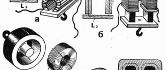
In Fig. 1 is a schematic diagram of the flow of electric current into the apartment from the general system. The letters $L1$, $L2$, $L3$ denote phases 1-3, and the letter $N$ denotes the neutral wire.
In Fig. Figure 2 shows a schematic connection of current to the apartment from the transformer, the letter $L_T$ denotes the phase on the transformer, the letter $L$ denotes the phase in the apartment, and the letter $R_H$ denotes a connected electrical appliance that has some resistance $R_H$.
There are 2 wires coming from the transformer, one is the so-called phase wire with voltage, and the other is the neutral wire, from which the grounding is carried out by placing the contact in the ground. There are other sources of grounding besides the ground itself; in these figures, grounding is indicated by the letters $Zml$.
In Fig. Figure 3 shows the case when the neutral grounded wire is not routed into the apartment from the substation, but is grounded directly in the apartment. The voltage $L_T$ between zero and phase will be the same for Figures 2 and 3, however, it is not recommended to ground the voltage from the transformer directly in the apartment.
Household electrical wiring device
A standard electrical wiring diagram contains the following elements:
- multi-tariff electricity meter;
- automatic switch with a rated current of 25 A;
- a shutdown mechanism that protects against short circuits and network overloads;
- differential circuit breaker with an operating threshold of 30 mA (leakage current), it protects sockets;
- cabinet for installation with busbars (neutral and grounding) and boards for installing switches;
- several lighting machines with a rated current of 10 A;
- cables with distribution boxes leading to sockets and devices that illuminate the premises.
Often apartment owners are interested in whether a phase is plus or minus, and what is the difference between zero and ground. Since the electrical phase has a variable potential, its indicator in the phase wire becomes either positive or negative. Therefore, it would be incorrect to say that phase is a minus (or a plus) - these concepts lie on different planes.
Now let's talk about how zero differs from ground. The difference is that current passes through the neutral wire and is opened by automatic devices (for example, the input wire). To ground in an apartment building, you need to connect to a conductor located in the riser, designed specifically for this purpose. It is strictly prohibited to use any other place, including the panel housing, for grounding - this can cause serious problems for the health of residents.
Options
In the characteristics of alternating current, there are basic and additional parameters.
- frequency;
- period;
- amplitude;
- effective value.
Additional:
- angular frequency;
- phase;
- instantaneous value.
Let's look at them in detail.
Frequency
The letter designation is f, the unit of measurement is hertz (Hz). Indicates the number of complete cycles of current oscillations per second.
The frequency of the alternating current at the output of the simplest generator is determined by the speed of its rotor. In the power supply system of Russia and other countries of the former USSR, a current with a frequency of 50 Hz is used.
Change curves of sinusoidal alternating current at different frequencies
In some cases, the frequency is increased by converting the current. For example, in inverter welding machines and pulse power supplies - up to 20 - 80 kHz. At this frequency, the dimensions of the transformer and losses in it are significantly reduced. In some devices the frequency is increased to several MHz.
Period
Designation - "T", unit of measurement - second. Period is the duration of a complete cycle of current oscillations. This parameter is related to frequency by the following relationship:
T = 1/f.
Accordingly, in the electrical network the current period is 1/50 = 0.02 s = 20 ms.
Amplitude
The maximum value of current or EMF corresponds to the top of the half-wave. Denoted, respectively, Im and Um. During the period, these values reach amplitude values twice - with a positive and negative sign.
Effective value
This is a direct current equivalent to a given alternating current in terms of work performed. Constantly changing alternating current is inconvenient to use in calculations, so it is replaced by the effective value. Denoted by the letters I and U.
For sinusoidal current and EMF is determined by the formula:
I = 2^(-1/2) * Im = (1/1.414) * Im = 0.707 Im;
U = 2^(-1/2) * Um = 0.707 Um;
Voltage 220 V in a household electrical network is the effective value. The amplitude is 311 V. Similarly, if they say that the load consumes a current of 5A, they mean the effective value. The current amplitude is 7.07 A.
Angular frequency
Indicates the rate of change of angle α in the EMF calculation formula. Corresponds to the angular frequency of rotation of the rotor. Since during one period the angle a changes by 2π at a standard frequency f = 50 Hz, the angular frequency will be: ω = 2π * 50 = 100 π.
Phase - the nature of the change in angle α relative to the time reference point. Currents and EMF can be in phase or have a shift. The latter is measured in radians, degrees or fractions of a period. When the phase shifts by π (1/2 period), the quantities are said to be out of phase.
AC current and voltage phase shift
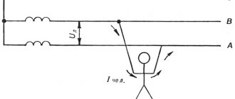
What happens in zero and phase when a wire breaks.
Line breaks quite often occur due to the fault of the craftsmen - they forget to connect a phase or zero. Such breakdowns are quite common. Also, quite often the process of zero burnout on the access panel occurs, for example, due to high load in the system.
If a break occurs in any part of the chain, the entire chain stops functioning, because it opens. In such situations, it does not matter at all which wire is damaged - phase or neutral. The same thing happens when there is a break between the distribution board of a high-rise building and the panel in the entrance. With such a gust, all consumers who were connected to this panel will be without electricity.
All the situations that we tried to describe above occur. They may seem complicated, but they pose no danger to humanity. After all, the break occurred in only one wire, so it is not at all dangerous.
A very alarming situation is when the contact between the ground loop at the substation and the middle point, to which all the voltage of the in-house panel is supplied, is lost.
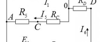
It is in this embodiment that the electric current moves along the contours AB, BC, CA. The total voltage of these circuits is 380V. It is for this reason that a rather dangerous situation arises - one panel may have no voltage at all, because the owner will turn off all electrical appliances, and a very high voltage level will form on the other, about 380V. This can contribute to the failure of many devices, because they require a voltage of 220V.
Naturally, this situation can be avoided. There is a lot of inexpensive/expensive equipment that will protect your equipment from power surges. Such equipment also includes a voltage stabilizer. There are the following types of stabilizers:
- Single phase;
- Three-phase.
Cable color marking
This is one of the simplest methods. To determine what phase and zero are by color, you need to clearly know which shades correspond to what. You can use information about the standards adopted in the country.
It's no secret that each wire has an individual color. Therefore, recognizing zero should not be a particular problem. The knowledge gained will allow you to easily cope with the installation of a lighting fixture or installation of an outlet. This method is especially relevant for new buildings. After all, there, as a rule, wires are laid by experienced specialists who strictly comply with norms and standards. The IEC 60446 standard, adopted on the territory of the Russian Federation in 2004, strictly regulates the separation of phase, grounding and zero by color.
It is worth considering that:
- if the wire has a blue or blue-white tint, we can safely say that this is a working zero
- the protective zero is represented by cables in a yellow-green sheath
- other colors are characteristic of the phase. It can be red, brown, white or black. Other options are also possible.
This designation is successfully used in most cases. But if the wiring is old, or there are doubts about the professionalism of electricians, it is more advisable to use additional methods.
Phase and zero: their meaning in the power supply network
Electricity is supplied to consumer sockets from substations, which reduce the incoming voltage to 380 V. The secondary winding of such a transformer has a “star” connection - its three contacts are connected to each other at the “0” point, the remaining three outputs go to the “A” / “B” terminals "/"WITH".
The wires connected at point “0” are connected to “ground”. At the same point, the conductor is divided into “zero” (indicated in blue) and a protective “PE” cable (yellow-green line).
This model of wiring is used in all houses currently being built. It is called the “TN-S” system. According to this diagram, three phase cables and two indicated zeros are suitable for the distribution equipment of the house.
In houses, enterprises and buildings of old construction there is often no “PE” conductor and therefore the circuit turns out not to be five-wire, but four (it is designated as “TN-C”).
All electrical wires from the substations are connected to the panel, forming a three-phase system. Then there is a division into separate entrances. Each of the entrance apartments is supplied with only one phase voltage - 220 V (wires “O” / “A”) and a protective “PE” cable.
With this scheme, the entire load on the power supply system is distributed evenly, since on each floor of the house specific panels are wired and connected to a specific 220 V power line.
The supply voltage circuit is a “star”, which exactly repeats all the vector characteristics of the supply substation. When there are no consumers in the sockets, no current flows in this circuit.
This connection scheme has been worked out for years. It confirmed its right to use by being recognized as the optimal of all existing ones. However, in it, as in any device, mechanism or device, all kinds of breakdowns and malfunctions may periodically appear. As a rule, they are associated with poor quality electrical connections or complete cable breaks in some places in the circuit.