Energy-saving lamps actually consume significantly less electricity than their filament counterparts, but they cost several times more than the latter. And, as practice shows, they fail more often. It’s doubly offensive when this happens two or three months after purchase. In such cases, you should not throw them in the trash for two reasons. First, these lighting products contain mercury, so they require disposal. Secondly, with a high degree of probability the lamp can be restored. Let's tell you how this can be done.
What are energy saving lamps
They are quite rightly called compact fluorescent lamps, and have firmly taken their rightful place in our everyday life. Even the higher price is not intimidating when it comes to possible subsequent savings (up to ninety percent) and efficiency of use.
But unpleasant surprises can be expected from them too. The myth of “eternity” often ends in disappointment when suddenly the “long-liver” refuses to work or simply breaks down.
- The reason for this may be a lack of power to the ballast or a coil that, alas, burned out.
- In this case, you can always take advantage of the excellent quality of such models - repair the lamps yourself.
- Many people are faced with this question, wanting to understand how and in what cases it is possible to restore functionality.
How fluorescent lamps work: 4 phases of start-up and shutdown - a simple explanation
Inside the sealed space of the glass flask there are mercury vapors that create an ultraviolet radiation spectrum. It is converted into visible light by a phosphor deposited on the inner surface of the tube.
The gas discharge that causes the glow flows between the electrodes formed by the filaments. To ignite it, a throttle and a starter are used.
Launch phase #1. Warming up the filaments
When voltage is applied to the lamp circuit by a switch, alternating current begins to flow through a closed circuit. Its path: inductor, one filament, starter capacitance, second filament.
The metal of both electrodes heats up, and electron emission is created around them, facilitating the occurrence of a gas discharge current.
Launch phase #2. Starter contact closure
The inductor, having inductive reactance, initially accumulates electromagnetic energy.
Inside the starter, a glow discharge is created between its electrodes, heating the bimetallic contact. The latter begins to bend and closes an additional circuit connected parallel to the electrodes. Current begins to flow through it.
The glow discharge stops. The bimetal cools down.
Launch phase #3. Gas discharge
The cooled bimetal of the starter disconnects the contact of the additional circuit.
When the circuit breaks, the choke generates an increased voltage pulse due to the imposition of a self-inductive emf on the 220 volt household signal.
A large surge of voltage between the electrodes of the flask breaks through the electrical resistance of the gaseous medium, creating a discharge current in it.
From the moment the gas discharge occurs, the choke limits the current in the circuit with its resistance and prevents an arc circuit. The lamp lights up.
At this stage, the starter has already completed its task and is not involved in the work.
Launch phase #4. Relieve voltage with switch
Breaking the power circuit stops the flow of the gas discharge and the glow of the lamp.
The described startup technology due to preheating of the filaments is called hot. It provides the most economical mode of creating loads on the built-in electrodes and provides them with an increased service life.
A fluorescent lamp can be put into operation faster, without heating the filaments. To do this, it is enough to apply an increased voltage pulse between them. This method is called a cold start. Its use significantly reduces the service life of the equipment.
Determining the extent of repairs needed
When answering the question of how expedient the repair is, it is worth taking an individual approach to solving the problem. And if you don’t mind the labor intensity, which, by the way, does not take much time due to the simplicity of the circuit, then it comes down to the availability of spare components.
Thus, it makes sense to start repairs only when at least ten light bulbs have accumulated. Then, having spent a little effort and time, as well as using the repair instructions, you can safely engage in such activities and reassemble two or three light bulbs suitable for use.
Another factor is working time. If the lamp has already been in use for one or a year and a half, then there is no need to “reanimate” it. There will be no required color rendering. In addition, part of the energy will be spent on heat during operation. The lamp should work for a short period of time, about the first few months.
Prevention of breakdowns
Knowledge of faults and monitoring of key indicators will help you avoid breakdowns of energy-saving lamps.
A short circuit inside the lamp may occur due to a manufacturing defect or insufficient heat dissipation. In any case, during operation the circuit overheats and the insulating layer is damaged. Eventually, some wires or contacts begin to touch each other. It is advisable to provide all lamps with sufficient ventilation and a well-thought-out heat dissipation system.
Video on the topic: 6 homemade products based on energy-saving lamps.
Often, in order to save money, manufacturers use low-quality components. This leads to breakdown of the ballast. The malfunction will quickly manifest itself under conditions of significant voltage drops. Therefore, it is better to equip the supply network with a high-quality stabilizer.
The problem of burnout is not alien to energy-saving lamps. It cannot be corrected or prevented. You can only create suitable conditions without voltage drops, frequent switching on and off, with a stable ambient temperature.
Repair
Repair of energy-saving lamps begins with an analysis of the principle of operation and its features, along with the elements present.
The lamp device consists of three parts:
- The most luminous element, that is, the flask;
- Electronic ballast - boards;
- Basement part.
It is necessary to carefully inspect the surface of the flask for the presence of cracks or chips. This is usually rare. The main reason for repairs is the failure of the electronic ballast, as well as burnout of the filament.
The lamp is disassembled very carefully with a flat screwdriver or knife. If the lamp body is damaged, this piece can be soldered or glued after the repair is completed.
After separation, the wires will require increased attention and may break. To prevent this from happening, they are carefully disconnected, and only then are both filaments checked for breakage by ringing. The integrity of both, says that the cause of the malfunction is in the ballast. If it is discovered that one of the threads has burned out, the bulb will require replacement.
Another option for repairing a burnt filament is to solder a suitable resistor in parallel. Despite a slight decrease in brightness, the lamp will still serve well.
- If one or more parts are found to be faulty, they are desoldered and replaced. This is what the stored lamps and their inspection are intended for.
- It is considered a great success when one lamp has a burnt-out filament, and the other has ballast. Then the working elements are simply replaced.
- Otherwise, more “creative” work awaits, when soldering is carried out with a tip, where copper wire with an optimal copper cross-section of four millimeters should be wound.
- A burnt capacitor can be seen without problems and can be replaced. It is worth remembering that the main reason for failure of Chinese-made lamps is capacitor failure.
- Before assembling the body part, a functionality test is carried out.
Such repairs are cheap and completely justified, especially if there is a certain supply of parts available.
Operating principle and diagram
When making repairs, it should be taken into account that the ESL consists of several elements: electrodes in the bulb, base (threaded, pin), starting device. Thanks to the built-in last element, the device is small in size.
Operating principle: when turned on, voltage is applied, resulting in heating of the electrodes. After which the released electrons interact with mercury atoms, ultraviolet radiation occurs. It is invisible to the eye. To do this, the system includes a substance called phosphor, which absorbs this radiation and produces the light we are familiar with.
The operation of an energy-saving light bulb is understood by examining the circuit. As an example, we describe the operation of an 11-watt light bulb.
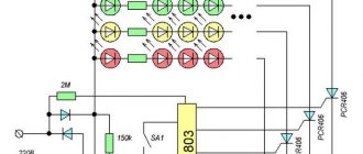
Diagram of operation of an 11 W lamp
From the diagram it can be seen that it consists of power circuits, which include inductor L2, fuse F1, four 1N4007 diodes make up a diode bridge, C4 is a capacitor, C2, D1, R6 are circuit elements, dinistor, D2, D3, R1, R3 - elements of the protective function. Not all light bulbs contain protective elements; manufacturers remove them to save on parts.
When the light bulb is turned on, a pulse is sent to C2, R6, it is supplied to transistor Q2, and it opens. After startup, diode D1 blocks part of the circuit. Transformer TR1 is excited by transistors. Capacitor C3 transmits voltage from circuit L1, TR1, C3, C6. The tube lights up when a voltage of 600V is reached at capacitor C3. When the lamp is ignited, the first transistor opens and the TR1 core is saturated.
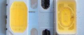
Signs of LED Burnout
How to repair an LED lamp? Not all lamps are capable of meeting the service life declared by the manufacturer. Differences in quality and price categories play an important role in this case.
When a lamp that costs one hundred and fifty rubles breaks down quite quickly, and when used at low power, a feeling of resentment arises. After all, in fact, one and a half and two years is not a long time for such a model. But most of them can be repaired.
Most lamps fail due to a malfunction of the LED, of which there are twenty-four in one product. The reason in many cases is the uncomfortable mode, since there is no aluminum radiator during acceleration much higher than the nominal value.
Wherein:
- The light bulb works like a regular backlight;
- Generally does not “want” to work without apparent reasons for burnout;
- The LED part darkens.
Finding faulty ballast elements
The condition of the board is first assessed visually. It is recommended to carefully examine all elements of the circuit from both sides. Under severe operating conditions, a short circuit or breakdown may occur.
In this case, it is easy to notice a change in the external characteristics of one or more board elements (deformation, blackening, etc.). If there are obvious problems, you should still check the entire circuit.
Debugg
The work is carried out in the following order:
- The bulb can be removed with a simple screwdriver if the diffuser is made of carbonate material;
- In practice, most often the connection is used in series, and the failure of one capacitor leads to the inoperability of the entire circuit and the lamp. Task number one is to find the faulty element. If this cannot be determined visually by external signs, then a multimeter is used;
- Identification of a faulty LED leads to the fact that all LEDs are removed and instead of the burned-out one, a new one is inserted onto the board along with the others. You can simply resolder the contacts;
- Having closed the circuit, it is necessary to check the lamp for operability.
Taking into account the fact that the cause of burnout of one of the soldered capacitors is the most common, it is worth, if possible, having a supply of suitable elements for the type, so that if repairs are necessary, you will always have them on hand in the required quantity.
How to disassemble
When disassembling the light bulb, the bulb is disconnected from the base. In this case, care must be taken, since the base is easily damaged. Use a screwdriver to disconnect the parts secured by the latches (the screwdriver penetrates the gap and turns the halves apart) - moves along the contour until the base and bulb are completely disconnected.
The wires that are directed to the filament are detached.
All work is carried out very carefully, since it is unacceptable to tear off the wiring that extends from the base.
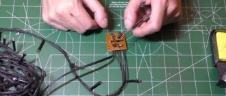
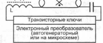
Once opened, the board of the electronic unit itself will be visible - a kind of starting device that is found in all original fluorescent lamps. Only modern ones are electronic, and in old ones there is a starter and throttle.
Photo of DIY repair of energy-saving lamps
Share with friends
External description
The lamp itself has the following device:
- Flask - looks like a spiral tube, attached to the body, filled with mercury and argon. There are two electrodes coming from the flask;
- The printed circuit board is ballast. The steering wheel of the ballast plays, regulates the heat mode;
- Fuse preventing short circuit and overload;
- Base that prevents corrosion; lower housing for protection against electric shock.
Connection to shu
to the horndriver
To install a switching power supply into a screwdriver, you will need to disassemble the power tool. As a rule, its outer part consists of two elements. The next step is to find the wires that connect the engine to the battery. They are the ones that need to be connected to the power supply (homemade) using heat shrink tubing. You can also solder the wires. It is strongly not recommended to twist them.
To bring the cable out, you will need to make a hole in the screwdriver body. It is also recommended to install a fuse that will protect the wire from damage at the base. To do this, you can make a special clip from thin aluminum wire.
Thus, converting the ballast circuit into a pulse unit will help replace a damaged battery in a screwdriver. In addition, if we take into account all the nuances from the field of economics during manufacturing, then we can say that making a UPS with your own hands is profitable.
Main performance characteristics
When choosing energy-saving fluorescent lamps, the following set of characteristics has a great influence on the scope of their further application:
- Power. Varies from 7 to 100 W and above. For domestic conditions, models up to 20 watts are sufficient (which is comparable in brightness to an incandescent lamp 5 times stronger!).
- Base modification. Selected based on the characteristics of the lamp.
- Flask geometry. It is taken into account according to the parameters of the lighting device and compliance with external conditions of use.
- Radiation temperature. Depends on the purpose of the illuminated objects.
- Lifetime. Varies from 5 to 12 thousand hours.
We calculate the capacity of the required voltage
To save money, capacitors with a small capacity are used. The ripple indicator of the incoming voltage will depend on them. To reduce ripple, it is necessary to increase the volume of capacitors; this is also done to increase the ripple rate only in the reverse order.
To reduce size and improve compactness, it is possible to use electrolyte capacitors.
For example, you can use capacitors that are built into photographic equipment. They have a capacity of 100µF x 350V.
To provide a power supply with an indicator of twenty watts, it is enough to use a standard circuit from energy-saving lamps and without winding additional winding on the transformers. In the case where the choke has free space and can accommodate additional turns, you can add them.
Thus, you should add two to three dozen turns of the winding to be able to recharge small devices or use the UPS as an amplifier for equipment.
20 watt power supply circuit
If you need a more effective increase in power rating, you can use the simplest copper wire coated with varnish. It is specially designed for winding. Make sure the insulation on the standard inductor winding is good enough, as this part will be affected by the incoming current. You should also protect it from secondary turns using paper insulation.
The current power supply model is 20 watts.
For insulation we use special cardboard with a thickness of 0.05 millimeters or 0.1 millimeters. In the first case, two words are needed, in the second, one is enough. We use the maximum cross-section of the winding wire; the number of turns will be selected by trial. Usually quite few turns are needed.
Reducing the transverse diameter of the wire used will of course increase the number of turns, but this will only have a negative effect on the power.
To be able to increase the power of the power supply to hundreds of watts, it is necessary to additionally tighten the pulse transformer and expand the capacity of the filter capacitor to 100 farads.
100 watt power supply circuit
To lighten the load and reduce the temperature of the transistors, radiators should be added to them for cooling. With this design, the efficiency will be around ninety percent.
Transistor 13003 should be connected
A transistor 13003 should be connected to the electronic ballast of the power supply unit, which can be secured using a shaped spring. They are advantageous in that there is no need to install a gasket with them due to the absence of metal platforms. Of course, their heat transfer is much worse.
It is best to carry out fastenings using M2.5 screws, with pre-installed insulation. It is also possible to use thermal paste that does not transmit mains voltage.