Topic 4 Rectifier devices
4.1 Composition and purpose of the elements of the rectifier device
Rectifier devices are designed to convert alternating current into current in one direction.
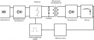
Figure 1. Block diagram of the rectifier device:
Tr—transformer; B - valve. SF - anti-aliasing filter, St - stabilizer
In the general case, the rectifier device includes a power transformer, a valve, a smoothing filter and a stabilizer (Figure 1).
There are two main types of rectifiers: half-wave and full-wave.
Depending on the number of phases of the supply network, rectifiers are divided into single-phase and three-phase.
Rectifiers can be controlled or uncontrolled. In controlled rectifiers, the value of the rectified voltage can be adjusted. To power most electronic devices, simpler uncontrolled rectifiers are used.
The transformer is designed to convert an alternating voltage, for example 220 V, into an alternating voltage of such a value that provides the required constant voltage at the output of the rectifier, for example 20 V.
The valve converts alternating voltage into pulsating voltage
Smoothing filter reduces rectified voltage ripple
The stabilizer maintains the load voltage constant.
The main elements of the rectifier are valves - nonlinear elements whose conductivity depends on the polarity of the applied voltage. Typically, semiconductor diodes are used as gates. The current-voltage characteristic of the diode is shown in Figure 2, a.
- The main parameters of rectifiers are:
Un.sr - average rectified voltage at the load;
I n av—average rectified current in the load;
P = Umain.out/ Un.av is the ripple coefficient of the rectified voltage (here Umain.out is the amplitude of the fundamental harmonic of the rectified voltage);
fn is the frequency of the fundamental harmonic of the rectified voltage (ripple voltage).
Figure 2 Half-wave rectifier:
a - I-V characteristics of the diode, b - rectifier circuit, c - voltage timing diagrams
The circuit of a half-wave rectifier is shown in Fig. 2, b.
- Alternating voltage from the secondary winding of transformer U2 is supplied to a circuit of series-connected diode D and load resistor Rн.
When the voltage half-cycle is positive, the diode is open and current flows through the load. When the half-term is negative, the diode is closed and there is no current in the load.
The rectified voltage Un can be represented as the sum of a constant Un.cp and a variable component (Fig. 2, c).
Typically, half-wave rectifiers are used to power low-power loads.
Among the full-wave single-phase rectifiers, the most commonly used rectifiers are those based on a midpoint transformer and a bridge rectifier.
Rectifier based on a midpoint transformer. The circuit of such a rectifier consists of two half-wave rectifier circuits, built on diodes D1 and D2 and operating on a common load RH (Figure 3, a).
During the positive half-cycle, current enters the load through diode D1, and during the negative half-cycle, through diode D2. As a result, two half-waves of voltage are applied to the load during a period (Fig. 3, b). The disadvantage of the rectifier is the complex design of the transformer and its inefficiency. The bridge rectifier does not have this drawback.
Figure 3 Full-wave rectifier based on a midpoint transformer:
a - rectifier circuit: b - time diagram of voltage at the load
Bridge rectifier. The rectifier consists of four diodes connected in a bridge circuit (Figure 4, a). Changes in supply voltage U2, diode currents, and load voltage are shown in Figure 4, b.
With a positive half-cycle voltage in the bridge circuit, diodes D2 and D4 are open and pass current to the load. Diodes D1 and DZ are closed at this moment. With a negative half-cycle of the voltage, diodes D2 and D4 close, but diodes D1 and DZ open and pass current into the load in the same direction.
Figure 4 Full-wave bridge rectifier: a - rectifier circuit: b - timing diagrams of voltages and currents
Compared to a half-wave rectifier, a single-phase full-wave rectifier provides a higher average voltage across the load, a smaller ripple amplitude and a higher frequency, which makes it easier to suppress ripple with smoothing filters.
Three-phase rectifiers are widely used to rectify three-phase voltage. The simplest circuit of a half-wave rectifier is shown in Fig. 5, a. This is a neutral point circuit. The phases of the secondary winding of the transformer are connected in a star. A diode is connected in series with the winding in each phase. The cathodes of the diodes are connected together. The load is switched between the common point of the cathodes and the neutral point
Currents flow through the diodes only at those moments in time when the anode potential is higher than the neutral point potential. The resulting current through the load is the sum of all three currents. Its change is reflected by the envelope in Figure 5, b.
Average rectified voltage across the load Un.av. = 1.17U2f.
The amplitude of the fundamental harmonic Umain.max = 0.29U2ph.
Pulsation coefficient p = 0.25.
Pulse frequency fп = 3f
Another three-phase rectifier circuit is known as the Larionov circuit. It consists of three bridge circuits operating on a single load (Fig. 6a).
In a three-phase full-wave rectifier, the diodes of each phase pass current into the load at both half-waves of the supply voltage. This allows you to significantly reduce the ripple of the rectified voltage (see the envelope in Fig. 6,b).
Average rectified voltage across the load Un.сp. = 2.34U2f.
Fundamental harmonic amplitude = 0.13 U2ph.
Ripple coefficient p = 0.057.
Pulsation frequency fп = 3f
In powerful three-phase rectifiers assembled using a bridge circuit, controlled valves—thyristors—are widely used. Such rectifiers are called controlled. By adjusting the opening moments of thyristors, it is possible to regulate the average value of the rectified voltage relatively easily and economically.
Figure 5 Three-phase half-wave rectifier: a - rectifier circuit;
b - time diagram of voltage at the load
Figure 6 Three-phase two-wave rectifier a - rectifier circuit, b - time diagram of voltage at the load
4.5 Anti-aliasing filters
To suppress the alternating component of the rectified voltage, smoothing filters are installed between the valve and the load.
The main parameter of the smoothing filter is the smoothing coefficient ????f. It is determined by the ratio of the ripple coefficients at its input and output:
????f =
In some devices, anti-aliasing filters are not needed at all. For example, in rectifiers for powering DC electric motors, since the motor rotor is not able to respond to high-frequency pulsations due to a significant moment of inertia, while in other motors the pulsation coefficient at the output of the power supply should not exceed 10 -6 (electron microscope drive power supply ), which requires installing filters with a very high smoothing coefficient.
The simplest anti-aliasing filters are inductive and capacitive.
The inductive filter (Figure 7,a) is a choke that is connected in series with the load.
Significant inductive reactance XL = 2fnL significantly reduces the alternating voltage component, practically without changing the constant one, since the active resistance R of the inductor is small.
With sufficient accuracy we can take ????ф = 2fnL /Rн.
Inductive filters are usually used in high-power low-impedance circuits.
Figure 7 Filter circuits
a - inductive; b - capacitive; c — L-shaped LC filter; g - U-shaped
LC filter. d - L-shaped RC filter
The capacitive filter (Figure 7, b) is a capacitor connected in parallel with the load. With a significant capacitance, the resistance for the alternating component of the rectified current is small (Хс = 1/(2?fnС) «Rн) and it passes through the capacitor, bypassing the load. Only the DC component of the rectified current enters the load.
You can also understand the principle of smoothing ripples by taking into account that as the voltage across the load increases, the diode is open and, due to its low resistance, the capacitor charges almost instantly. As the voltage decreases, the diode closes and the capacitor discharges relatively slowly through a load resistance greater than that of the diode.
With sufficient accuracy for a full-wave rectifier with a capacitive filter, we can take ????ф = 1.34fnСRн.
Capacitive filters are mainly used in low-power, high-resistance circuits.
To ensure high-quality smoothing, inductive and capacitive filters are combined to form L-shaped (Figure 7, c) or U-shaped (Figure 7, d) LC filters. The smoothing coefficient in this case is equal to the product of the smoothing coefficients of the filter sections.
In low-power sources, an L-shaped RC filter is used (Figure 7, e).
Problem 1. According to the reference data, the 2Ts103A rectifier column has a forward voltage drop of 7V at a current of 40 mA, and at a reverse voltage of 2,000 V, the reverse current is 0.1 μA. Calculate the forward and reverse resistances of the diode.
Solution. The data presented make it possible to determine the static resistance for the forward and reverse branches of a high-voltage rectifier column in accordance with Ohm's law. Direct resistance Rnp = Upr/Ipr = 7 V/0.04 A = 175 Ohm, reverse resistance p = Rrev/Irev = 2,000 V/(0.1 • 10 -6 A) = 2 • 1010 Ohm. Calculations show that the direct resistance of a high-voltage rectifier column can be hundreds of ohms. while the reverse resistance is in the tens of gigaohms (1 GOhm = 109 Ohms).
Answer. The forward resistance of the 2Ts103A rectifier column is 175 Ohms, the reverse resistance is 2•1010 Ohms. Thus, the reverse resistance is more than 108 times greater than the forward resistance.
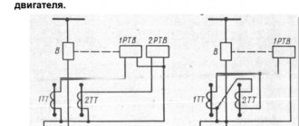
Task 2. To operate a DC electric motor DPM-30-N2 from an industrial network with a voltage of 220 V and a frequency of 50 Hz, a rectifier is used. A motor with permanent magnet excitation has the following main electrical parameters:
Un= 27 V; In = 0.7 A.
Select a rectifier circuit and calculate the parameters of its main elements.
Solution. In this case, to power the electric motor, it is enough to have only two elements: a transformer and a valve. This is due to the fact that a sufficiently high ripple frequency of the rectified voltage has virtually no effect on the performance characteristics of the engine. It responds only to the average rectified voltage Un.av.
Based on the characteristics of the motor, we select as a valve the rectifier unit KTs402 with a bridge connection circuit, which has the following parameters: Urev.max = 100 V,
I pr. max = 1,000 mA. The motor can be connected directly to the diagonal of the bridge with a pulsating voltage, while the second diagonal is connected to the secondary winding of the transformer (Figure 8).
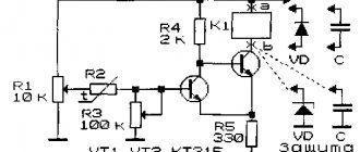
Figure 8. DC motor power supply circuit for task 2
Since for a full-wave single-phase rectifier Un.cp = 0.9 U2, the effective voltage value on the secondary winding of the transformer is U2 = Un.cp / 0.9 = 27/0.9 = 30 V.
Thus, for the rectifier to operate, a transformer with a primary voltage U1 = 220 V and a secondary voltage U2 = 30 V is required. Rated power of the transformer
Pnom = U2 • In = 30 • 0.7 = 21 W.
Answer. To operate a DC motor from an alternating voltage source of 220 V, it is advisable to use a rectifier unit KTs402, operating in conjunction with a transformer, the secondary voltage of which is 30 V and the rated power is 21 W.
Task 3 Calculate the current stabilization coefficient if, at the rated output
At a current of 5 A, the rated output voltage is 20 V. In this case, a change in the load current in the range from 3 to 7 A leads to a change in the output voltage by 0.4 V.
Solution. Flux stabilization coefficient, which determines the range of change in output voltage ?Ucall when the load current changes ?In,
Kst 2 = ?In / In. nom.)/(?Uout./Uout.nom.) = (4/5)/(0.4/20) = 40.
Answer. The current stabilization coefficient is 40.
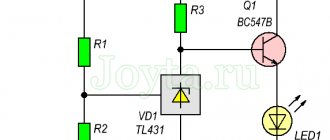
Task 4 To ensure a stable voltage Uout = 4 V on a load with resistance Rн = 120 Ohms, a parametric voltage stabilizer is used (see Figure 9.a). The range of input voltage changes is 6 ... 10 V. Determine the resistance of the ballast resistor Rb and its dissipation power, and also select the type of zener diode.
Solution. We calculate the load current: In = Uout / Rн = 4/120 = 0.033 A.
We find the resistance of the ballast resistor: Rb = (Uin.min – Uout)/In=(6 - 4)/0.033 = 61 Ohm.
We determine the maximum current consumed by the EC: 1max = Uin.max –Uout / Rb = (10-4)/61 = 0.1 A.
We calculate the maximum current through the zener diode: Id.max.= Imax –In = 0.1 -0.033 = 0.067 A.
Using the reference book, we select the type of zener diode that provides an output voltage of 4 V and is designed for a maximum current of at least 0.067 A.
These requirements are met by the KS139A zener diode with the parameters Est. = 3.9 V and
Ist. out = 70 mA.
We calculate the maximum power of the ballast resistor: P = I2 out = 0.01 • 61 = 0.61 W.
Answer. To stabilize the output voltage of 4 V on a load with a resistance of 120 Ohms, a KS139A zener diode can be used together with a ballast resistor, for example MLT-1-62
Figure 9. Circuit [a] and current-voltage characteristic [b]
parametric stabilizer
for independent decision
Task 5 Using the current-voltage characteristics of the KTs407A diode bridge (Fig. 10) for temperatures of -60, +25 and +85°C, determine the values of the static resistance of the diode in the forward direction at Ipr = 40 mA. Compare these values.
Task 6. Using the current-voltage characteristics of the KTs407A diode bridge (see Fig. 10, b), determine the values of its static resistance for three temperatures when turned on in the reverse direction, if a reverse voltage Urev = 150 V is applied to the diode. Compare these values.
Problem 7. How are semiconductor diodes connected in circuits with currents exceeding the direct current of the diodes used?
Problem 8. How semiconductor diodes are connected in voltage circuits. exceeding the maximum permissible reverse voltage of the diodes used?
Problem 9. Determine the current flowing through a load resistor with a resistance
Rn = 140 Ohm of the bridge rectifier, if the voltage U1max = 160 V is supplied to the primary winding of the transformer, the transformation ratio K21 = 0.1. and the resistance of each semiconductor diode in the circuit is 10 ohms.
Problem 10. Calculate the ripple coefficient at the output of an inductive filter with an inductance of 0.8 H, operating on a load with a resistance of 50 Ohms, if the voltage at the filter input comes from a full-wave rectifier powered by an alternating voltage with a frequency of 50 Hz.
Problem 11. Calculate the ripple factor at the output of a 200 µF capacitive filter operating on a load with a resistance of 1 kOhm. if the voltage at the filter input comes from a dual-wave rectifier powered by an alternating voltage with a frequency of 50 Hz.
Problem 12. A zener diode with an ideal current-voltage characteristic is used in a parametric voltage stabilizer circuit. It is known that Uвx = (16 ± 1.6) V,
Ust = 9 V, Ist = 10 mA, load current In = 8 mA. Determine the current at the input of the stabilizer Iin and the resistance of the ballast resistor Rb.
Problem 13. In Fig. 11 connect the individual blocks of the block diagram of the rectifier device to each other in the required sequence.
Rice. 10 Current-voltage characteristics of the KTs407A diode bridge (for tasks 5 and 6)
Figure 11. Block diagram of the rectifier device (for problem 13)
Uncontrolled rectifiers
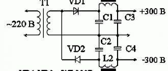
Diodes allow current to flow in only one direction: from the anode (A) to the cathode (K). As with some other semiconductor devices, the diode current cannot be adjusted. The AC voltage is converted by the diode into a pulsating DC voltage. If an uncontrolled three-phase rectifier is powered by three-phase AC voltage, then in this case the DC voltage will pulsate.
The output voltage of the uncontrolled rectifier is equal to the difference in voltages of the two diode groups. The average value of ripple DC voltage is 1.35 x mains voltage.
The AC voltage rectifier (converter) is assembled using diodes or thyristors; it is also possible to combine them. a converter assembled with diodes is completely uncontrolled, while one made of thyristors is, on the contrary, fully controlled. If thyristors and diodes are used, then the voltage converter is called semi-controlled.Uncontrolled converter
When using a diode bridge, current flows in only one direction: from the anode of the diode to its cathode, while the effective value of the current flowing through the diode is not regulated in any way. At the input of the rectifier there is an alternating sinusoidal voltage, at the output there is a constant voltage with a certain degree of ripple.
The output voltage of a single-phase diode converter is equal to the difference in voltages of two diode groups, and the average rectified value of the DC output voltage is equal to 0.9 of the effective value of the network voltage. That is, if the network voltage is 220 V, then the rectified voltage is 200 V.
Controlled converter
In controlled rectifiers, thyristors are installed instead of diodes. A thyristor has a property similar to a diode - current also flows through it in one direction. But in addition to the diode, the thyristor has a third terminal, called the “control electrode” (CE). In order for the thyristor to turn on, a control voltage pulse must be applied to the control electrode.
The thyristor cannot be de-energized by sending a signal through the control circuit. To turn it off, two conditions must be met: the current through the thyristor is reduced to zero and the control voltage is briefly applied.
A control signal α is applied to the control electrode of the thyristor, which is characterized by the delay time for unlocking the switch, reduced to electrical degrees. This value determines the turn-on delay of the thyristor relative to the moment of zero crossing of the mains voltage.
A controlled rectifier in its essence is not very different from an uncontrolled one. The only difference is that the thyristor turns on only from the moment a control pulse is applied to it, due to which it becomes possible to regulate the output voltage and current
A controlled rectifier (or, in other words, a thyristor converter) has a slightly lower efficiency compared to an uncontrolled one due to switching losses of thyristors, and also introduces large impulse noise and nonlinear distortions into the network; In addition, the controlled converter is a source of reactive power consumption even with a purely active load.
.
Comparison of single-phase bridge controlled rectifier circuits
The article is devoted to a comparison of circuits of single-phase bridge controlled rectifiers used in converter technology.
Key words: controlled rectifier, zero valve, galvanic isolation, controlled valve.
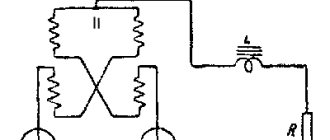
The bridge single-phase controlled rectifier contains four controlled valves, which require at least three galvanically isolated signals from the control system. The last problem is solved by using optothyristors. Or the thyristors are controlled through a special pulse transformer (Fig. 1).
Rice. 1. Single-phase bridge controlled rectifier
The advantages of a single-phase bridge controlled rectifier include a simpler transformer, in contrast to a zero switching circuit, and the rectifier can also operate without a transformer if galvanic isolation or network matching by voltage level is not required, the following advantages are high efficiency and low ripple of the rectified voltage.
The disadvantages include the large number of elements of the rectification circuit, as well as the complexity of controlling them.
If a single-phase bridge controlled rectifier is not used in inverter mode, then the same parameters relative to a circuit with four controlled valves can be achieved by cheaper means. Let's consider three variants of circuits with an incomplete number of controlled valves:
Circuit A (Fig. 2) is the most understandable, since it is similar to the circuit of a fully controlled rectifier. Galvanic isolation B1, B2 is required. Diodes D3, D4 perform the function of a zero gate when both thyristors are locked.
Rice. 2. Single-phase bridge controlled rectifier with an incomplete number of controlled valves according to switching circuit A
In circuit B (Fig. 3), pulses can be applied to both thyristors at once: only the first one, which has a positive voltage, is unlocked. The functions of the zero valve are performed alternately by B1, D2, B3, D4.
Rice. 3. Single-phase bridge controlled rectifier with an incomplete number of controlled valves according to connection diagram B
The third circuit B (Fig. 4) is the cheapest, since it contains only one controlled valve. The use of a zero valve with an inductive load is mandatory, since the RNT does not have conditions for closing the controlled valve B1.
Rice. 4. Single-phase bridge controlled rectifier with an incomplete number of controlled valves according to connection diagram B
As was said earlier, the choice of controlled single-phase bridge rectifier circuits with an incomplete number of controlled valves is justified by their lower cost, as well as simpler control, relative to a circuit with a full number of controlled valves.
Conclusion
This article examined single-phase bridge controlled rectifiers and their varieties, as well as their advantages and disadvantages.
Literature:
1. Gorbachev G. N., Chaplygin E. E., Industrial electronics: Textbook for universities. Ed. V. A. Labuntsova. - M.: Energoatomizdat, 1988. - 320 p.
- Zinoviev G.S. Fundamentals of power electronics: Textbook for universities. - Novosibirsk: Publishing house of NSTU. 2004. - 664 p.
- Semenov V.D., Mishurov V.S. Fundamentals of converter technology. Training manual. — Tomsk: Tomsk Interuniversity Center for Distance Education. 2002.- 132 p.
Single-phase bridge rectifier, operating principle, description
The rectifier in question (Fig. 4.21) is widely used in a wide variety of relatively low-power devices (up to hundreds of watts and, sometimes, units of kilowatts).
Let us describe the operation of the rectifier for two characteristic types of load: active (Fig. 4.21, a) and actively inductive (Fig. 4.21, b).
Operation of the rectifier for an active load at zero control angle. For the rectifier under consideration, the control angle is called the angle a of the phase shift between the beginning of each positive half-wave of the supply voltage iin and the corresponding moment of turning on the thyristors T, and T4, as well as the shift angle equal to it between the beginning of each negative half-wave of the voltage iin and the corresponding moment of turning on the thyristors T2 and T3 (thyristors are switched on in pairs).
When a = O, the electrical processes in the controlled rectifier coincide with the processes in the uncontrolled rectifier discussed above. Naturally, the mathematical expressions characterizing the rectifier remain the same.
Operation of the rectifier for an active load at a control angle i/2 rad (90 el. deg.) (Fig. 4.22).
The analysis of processes in the rectifier at a non-zero control angle a becomes more complicated, since on some segments of the abscissa axis (and on some periods of time) all the thyristors of the circuit are turned off and the problem of distributing the voltage I/O across them has to be solved. In this case, two thyristors are under direct voltage, and the other two are under reverse voltage.
We assume (this is generally accepted) that the equivalent resistances of all turned off thyristors are the same and do not depend on the voltage polarity. In this case, the voltage on each pair of thyristors, one of which is under forward voltage and the other under reverse voltage, is divided equally (this is easy to understand if you mentally replace all four turned off thyristors with resistors with the same resistances). This is exactly how time diagrams are depicted on the x-axis segments 0...I/2, l..!(3/2)I, etc.
When w*t=p/2, thyristors T3 and T4 are turned on. At the same time, the reverse voltage on thyristors T2 and T3 doubles abruptly.
Similarly, after turning on thyristors T2 and T4, the reverse voltage on thyristors T1 and T4 increases. Thyristors T2 and T3 are turned off at сonst = 2p.
Analysis of a circuit with thyristors turned on is simple.
Like an AC breaker, at O the rectifier consumes a current from the supply network with a shape very different from the sinusoidal one.
The control characteristic of a controlled rectifier is the dependence of the average value Ucp of the rectified voltage on the control angle. The graph of this dependence is also called a regulatory characteristic.
The control characteristic of a rectifier operating on an active load has the form
Let's draw the corresponding graph (Fig. 4.23, solid line). The operation of the rectifier on an active-inductive load at zero control angle (Fig. 4.24).
We assume (as is generally accepted) that the load inductance LH is very large, so that the load current ieblx is practically constant. This assumption can be used if the load time constant xn is significantly greater than the period of the network voltage.
Operation of the rectifier on an active-inductive load at a control angle i/4 rad (45 el. deg.) (Fig. 4.25).
Under the accepted condition of a significant influence of inductance, one pair of thyristors is open at each moment of time (the electromotive force of self-induction prevents a certain pair of thyristors from being turned off before the next pair is turned on). This simplifies the analysis of the circuit.
The timing diagram of the input current iex is shifted relative to the voltage diagram iex and, therefore, the fundamental harmonic of the input current is out of phase with the supply voltage.
From the above it follows that in the mode under consideration, the rectifier loads the supply network with reactive power and this, of course, is a negative factor.
The regulating characteristic of a rectifier operating on an active-inductive load is determined by the expression, since the average voltage across an ideal inductor is zero (otherwise its current would increase to infinity). The power Рн consumed by the resistor RH of the active-inductive load is calculated by the formula (max, since the current ieblx is constant, its effective and average values coincide).
Cheat sheets for exams and tests
| See also... |
| Cheat sheets on electrical engineering and electronics |
| Ohm's law for a closed circuit and for a section of a circuit |
| Kirchhoff's laws for a DC circuit |
| Calculation of simple circuits for various consumer connection schemes |
| Concept of a complex electrical circuit |
| Power, operation and efficiency losses of electrical circuits |
| Sinusoidal current and its main parameters |
| Ways to represent sinusoidal current |
| Resistor resistance in a sinusoidal current circuit |
| Capacitor in a sinusoidal current circuit |
| Inductance in an electrical circuit |
| Law of Electromagnetic Induction |
| Inductance in a sinusoidal current circuit |
| Mutual inductance in magnetically coupled circuits |
| Kirchhoff's laws for sinusoidal current circuits |
| Ohm's law and the resistance of a sinusoidal current circuit with a series connection of elements R, L, C |
| The concept of voltage resonance |
| Stress resonance and its symptoms |
| Ohm's law and conductivity of a sinusoidal current circuit with parallel connection of branches RL, LC |
| Concept of resonance currents |
| Instantaneous power of a sinusoidal current circuit |
| Active, reactive and apparent power of sinusoidal current circuits |
| Power factor and its economic significance |
| Obtaining a three-phase EMF system and methods of presentation |
| Winding connections of three-phase generators |
| Connections of receivers in three-phase circuits |
| Three-phase power |
| Transformers |
| Operation of transformers in various modes |
| Transformer losses and efficiency |
| Device, diagrams and connection groups of windings of three-phase transformers |
| Purpose, circuit and operation of the autotransformer |
| Purpose, circuit and operation of a pulse transformer |
| DC machines |
| Asynchronous electric motors |
| Synchronous electric motors |
| Starting equipment |
| Selecting the type and power of the electric motor |
| Wires and cables, selection of wire cross-section |
| Protective grounding |
| Electron-hole transition |
| Diodes, thyristors |
| Transistors |
| Basic logical operations and their implementation |
| Triggers |
| Single-phase uncontrolled rectifiers |
| Three-phase rectifiers: zero, bridge |
| Filters(C, L, LC, RC), ripple factor |
| Single-phase and three-phase controlled rectifiers |
| All Pages |
Page 46 of 49
Single-phase uncontrolled rectifiers: half-wave, full-wave with transformer midpoint output, bridge
Rectifier devices belong to secondary power sources, for which the primary source is AC networks. A rectifier is a device that converts the alternating voltage of the supply network into a unidirectional pulsating one. It is unidirectional pulsating and calling it constant is a little incorrect. There is also a slightly different definition: a rectifier is designed to convert alternating voltage into pulsed voltage of the same polarity.
Semiconductor diodes are most often used in rectifiers. The principle of rectifying alternating voltage is based on the nonlinear current-voltage characteristic of a semiconductor diode, in which the resistance in the forward and reverse connection of the pn junction is very different.
Rectifiers can be half-wave or full-wave. In addition, they are divided into single-phase and multiphase.
So, let's start with a single-phase, half-wave rectifier based on a semiconductor diode.
Rice. 1 - Diagram of a single-phase half-wave rectifier and graphs explaining the principle of its operation.
The circuit of a half-wave rectifier is painfully simple and there is nothing to explain here. For clarity, positive and negative half-waves are shown in different colors. Since the diode has one-way conductivity properties, the output produces a pulsating voltage of one polarity. The scheme is characterized by the following parameters:
Average value of rectified voltage: Uav=bxsinωtdωt ≈ 0.45Ubx
Effective value of input voltage: Ubx=≈2.22Uav
Average value of rectified current: Iav=
Effective current value in the secondary winding of the transformer:
I2==≈1.57Iav
Ripple factor p==
The advantages of the scheme include the simplicity of the design. Disadvantages: large ripples, low values of rectified current and voltage, low efficiency. This circuit is used to power low-impedance loads that are not critical to high ripples.
1. Rectification circuit with output from the middle point of the transformer.
Rice. 2 - Diagram of a full-wave rectifier with output from the midpoint and graphs explaining the principle of its operation
The dotted line shows the voltage at the input of the second diode. As can be seen from the graphs, during the first half-cycle the first diode is open and a voltage drop is created across the load. During the second half-cycle, the first diode closes because it turns on in the opposite direction, and the second, on the contrary, opens and a positive half-wave is again released at the load. In the diagram, pluses and minuses indicate the action of half-waves of alternating current. The ripple frequency of a full-wave rectifier is twice as high, which is its advantage. The following parameters are typical for such a circuit: Uav = 0.9Uin
Uin = 1.11Uav
Iav = 0.9Uin/Rn
I2 = 0.78Iav
p = 0.67
Advantages: doubled values of Uav and Iav, half the ripple coefficient compared to a half-wave circuit. Disadvantages: the presence of a transformer with two symmetrical windings (which increases its weight and dimensions). In addition, the diodes have double the reverse voltage.
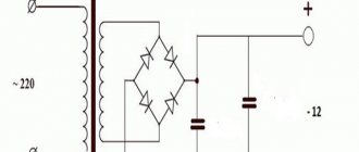
2. Bridge circuit
Rice. 3 - Bridge rectification circuit
The parameters are the same as for a full-wave circuit with an average output, except for the reverse voltage (it is half as much). The positive half-wave (from the top transformer output in the diagram) passes through diode VD2, then through the load, then through VD3 to the second output of the transformer. When the direction of the current changes, diodes VD4, VD1 operate. The disadvantage of the circuit is the double number of diodes.