1. Main characteristics of OZZ
One of the most common types of faults on power lines is a single-phase ground fault (SGF), a type of fault in which one of the phases of a three-phase system is shorted to ground or to an element electrically connected to ground. SPD is the most common type of damage, accounting for about 70-90% of all damage in electrical power systems. The course of physical processes caused by this damage largely depends on the operating mode of the neutral of a given network.
In networks where a grounded neutral is used, a phase-to-ground fault results in a short circuit. In this case, the short-circuit current flows through a closed circuit formed by grounding the neutral of the primary equipment. Such damage leads to a significant jump in current and, as a rule, is immediately turned off by the action of a relay protection, by disconnecting the damaged area.
Electrical networks of voltage classes 6-35 kV operate in a mode with an isolated neutral or with a neutral grounded through a large additional resistance. In this case, a phase-to-ground short circuit does not lead to the formation of a closed circuit and the occurrence of a short circuit, but the short circuit is closed through the capacitances of the undamaged phases.
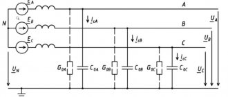
The magnitude of this current is insignificant (reaches about 10-30 A) and is determined by the total capacity of the undamaged phases. In Fig. Figure 1 shows diagrams of a 3-phase network in modes before and after the occurrence of an electrical fault.
Figure 1 – Network diagram with an isolated neutral a) in normal mode;
b) with OZZ Such damage does not require immediate shutdown, however, its prolonged impact can lead to the development of an emergency situation. However, during OZZ in networks with an isolated neutral, processes occur that affect the operating mode of the electrical network as a whole.
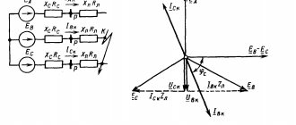
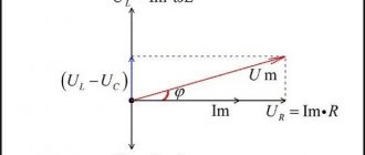
In Fig. Figure 2 shows a vector diagram of voltages.
Figure 2 – Voltage vector diagrams a) in normal mode; b) with acute respiratory disease
In the case of OZZ, a violation of the symmetry of linear phase voltages occurs, the voltage of the damaged phase decreases to almost 0, and the two “healthy” phases rise to the linear level. In this case, the linear voltages remain unchanged.
Ferroresonance and methods of protection against it
A ferroresonant circuit in a network with an isolated neutral is a zero-sequence circuit with a nonlinear magnetization characteristic. A three-phase grounded voltage transformer, by design, consists of three single-phase transformers connected in a star/star configuration with a separate magnetic system. During overvoltages in the network, the induction in the magnetic circuit increases by at least 1.73 times. In such modes, saturation of the magnetic circuit is possible and, as a consequence, the occurrence of ferroresonance in the network. According to energy supply services, every year 7–9% of voltage transformers are damaged in operation due to ferroresonance.
There are many ways to protect VTs from resonance phenomena in the network:
- production of VT with the most reduced working induction;
- inclusion of additional damping resistances in the HV and LV circuit;
- production of three-phase voltage transformers with a single magnetic system in a five-rod design;
- the use of special devices included in the open delta circuit;
- grounding the neutral of a three-phase voltage transformer through a current-limiting reactor;
- use of special compensation windings, etc.;
- the use of special relay circuits to protect the HV winding from overcurrents.
All these measures protect the voltage measuring transformer to one degree or another, but do not solve the problem fundamentally.
Consequences of OZZ
Despite the advantages of an isolated neutral, this operating mode has a number of disadvantages:
- Depending on the branching of the network, the capacitive current can range from 0.1 to 500 amperes. This amount of current can pose a danger to animals and people located near the fault; for this reason, these faults must be identified and turned off, just as is done in networks with a solidly grounded neutral.
- In most cases, an arc fault to ground occurs during a short-circuit fault, which can be intermittent. In this case, during an arc fault, overvoltages occur that exceed the rated phase voltage by 2-4 times. The insulation during the circuit may not withstand such overvoltages, as a result of which insulation breakdown may occur at any other point in the network and then the circuit develops into a double short circuit to ground.
- During the development and elimination of short-circuit faults, a ferroresonance effect occurs in voltage transformers, which with a high probability leads to their premature failure.
Despite the listed disadvantages, the OZ does not require immediate damage elimination. According to the PUE, in the event of an emergency, it is possible to operate the network without shutting down the accident for 4 hours, which are allocated to search for the damaged area.
The principle of operation of the protection
For four-pole circuit breakers and three-pole circuit breakers with an additional current transformer in the N-conductor circuit, the earth fault (G) protection calculates the vector sum of the currents of the three phases and the neutral conductor. In a closed circuit, this amount, called leakage current, is zero.
Id =IL1 + IL2 + IL3 + IN = 0.
When a phase is shorted to ground, part of the current, depending on the path of its return to the power source, is not closed through the neutral conductor, and the sum of the phase and neutral currents is not zero.
Id =IL1 + IL2 + IL3 + IN ≠ 0
Short circuit to ground in the TN-S system four-pole circuit breaker
For three-pole circuit breakers where there is no need for an N conductor (for example, for symmetrical three-phase loads such as three-phase motors), the earth fault (G) protection calculates the vector sum of the three phase currents. In the absence of a ground fault, the sum of the currents of the three phases in such a system is zero
Id =IL1 + IL2 + IL3 = 0.
When a phase is short-circuited to ground, part of the current, depending on the current path, is short-circuited through the ground or the PE conductor, as a result of which the sum of the phase currents is not equal to zero.
Id =IL1 + IL2 + IL3 ≠ 0
Short circuit to ground in the TN-S system three-pole circuit breaker
If the root-mean-square value of the vector sum of currents exceeds the set shutdown value Ig during the set delay tg, the protection is triggered.
Id ≥ Ig.
Calculation of the total current of the residual current
When a phase of one of several power lines connected to a common source is faulted to ground, the total current at the point of fault due to the capacitive currents of all power lines can be calculated by several methods.
The first method is to use the specific capacitances of power lines. This calculation method will give the most accurate result and is preferred. The specific capacitances of power lines can be taken from reference literature, or from the technical characteristics of the cable provided by the manufacturer.
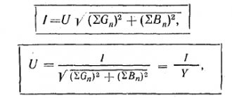
Expression for determining the residual current:
,
where C∑ is the total phase capacity of all power lines, and C∑ = Court l; Court – specific capacity of the network phase relative to ground, F/km; l is the total length of the conductor of one phase of the network.
The second method is applicable for networks with cable power lines. The ground fault current for such a network can be determined by the empirical formula:
,
where UNOM is the rated line voltage of the network, kV; li – cable line length, km; qi – cable core cross-section, mm2.
In addition to these methods, to calculate the total SGC current, you can use the values of capacitive currents of each cable taken from reference literature.
Calculation of single-phase ground fault current in a network with an isolated neutral
In this example, we will consider the calculation of the single-phase earth fault current (SGC) for a 10 kV substation (Substation diagram is shown in Fig. 1). Relay protection and automation of all feeders is carried out on microprocessor terminals SEPAM S40 (Schneider Electric).
Fig. 1 - 10 kV substation diagram
1. To increase the accuracy of our calculations when determining the OZZ, we use a method based on determining the specific capacitive ground fault current. (Also, the values of specific capacitive ground fault current can be used from reference data from Table 1, or taken from the technical characteristics of the cable provided by the manufacturer)
Where:
- Uph - phase voltage of the network, kV;
- ω = 2Пf = 314(rad/s);
- Co is the capacity of one phase of the network relative to ground (μF/km);
2. After we have determined the specific capacitive current of a ground fault, we calculate the cable line’s own capacitive current:
Table 1 - Specific values of capacitive currents in cable networks (A/km)
The calculation results are entered into table 2. Table 2 - Calculation results
| Name of connection | Protection relay type | Cable brand, cross-section, mm.kv | Length, km | Specific capacitive ground fault current Ic, A/km | Own capacitive current of the cable line Ic.fid.max, A |
| CL-10 kV No. 1 | SEPAM S40 | APvEVng-3x120 | 0,5 | 1,89 | 0,945 |
| CL-10 kV No. 2 | SEPAM S40 | APvEVng-3x95 | 0,3 | 1,71 | 0,513 |
| KL-10 kV No. 3 | SEPAM S40 | APvEVng-3x70 | 0,7 | 1,55 | 1,085 |
| KL-10 kV No. 4 | SEPAM S40 | APvEVng-3x95 | 0,3 | 1,71 | 0,513 |
| KL-10 kV No. 5 | SEPAM S40 | APvEVng-3x70 | 0,2 | 1,55 | 0,31 |
| KL-10 kV No. 6 | SEPAM S40 | APvEVng-3x95 | 0,6 | 1,71 | 1,026 |
3. We calculate the tripping current of the protections, while we tune out our own capacitive current using the formula (this condition ensures that the protection does not operate in the event of an external single-phase ground fault):
Where:
- Kn – reliability coefficient (assumed equal to 1.2);
- Kbr is the “surge” coefficient, which takes into account the surge of capacitive current at the moment when the SGC occurs;
- Ic.feed.max – maximum capacitive current of the protected feeder.
For electromechanical relays, it is recommended to take Kbr = 2–3. In this case, the protection is performed without a time delay. When using modern digital relays for protection against OZZ, you can take values of Kbr = 1–1.5 (please note that it is better to check this coefficient with the manufacturer). For SEPAM S40 it is recommended to take CBR = 1-1.5. The primary tripping current of the protections is:
- CL-10 kV No. 1 Iсз = 1.134 A;
- CL-10 kV No. 2 Iсз = 0.62 A;
- CL-10 kV No. 3 Iсз = 1.3 A;
- CL-10 kV No. 4 Iсз = 0.62 A;
- CL-10 kV No. 5 Iсз = 0.37 A;
- KL-10 kV No. 6 Iсз = 1.23 A
4. We check the sensitivity of the protections, taking into account that the minimum number of enabled lines will be turned on, in our case these are all connections that are located in the section.
Please note that the sensitivity coefficient according to PUE clause 3.2.21 is equal to: for cable lines - 1.25, for overhead lines - 1.5. In the book “Calculations of relay protection and automation of distribution networks. M.A. Shabad -2003" is given Kch = 1.5-2.0. In this calculation, I take the sensitivity coefficient according to the PUE. It’s up to you to choose which sensitivity coefficient to take.
where: IсΣmin is the smallest real value of the total capacitive current.
In my case, the smallest real value of the total capacitive current is the total capacitive current by sections:
- Section I - IсΣmin = 2.543 (A);
- Section II - IсΣmin = 1.849 (A);
5. Determine the response time of protection against short-circuit protection: For all outgoing cable lines of 10 kV, the response time of the protection is taken to be 0.1 sec. Table 3 — Results of calculations for the operation of protection against SPD
| Name of connection | Protection relay type | Primary operating current Iсз, A | Protection response time, sec | Sensitivity coefficient, Kh |
| CL-10 kV No. 1 | SEPAM S40 | 1,134 | 0,1 | 1,4 > 1,25 |
| CL-10 kV No. 2 | SEPAM S40 | 0,62 | 0,1 | 3,27 > 1,25 |
| KL-10 kV No. 3 | SEPAM S40 | 1,3 | 0,1 | 1,12 < 1,25 |
| KL-10 kV No. 4 | SEPAM S40 | 0,62 | 0,1 | 2,2 > 1,25 |
| KL-10 kV No. 5 | SEPAM S40 | 0,37 | 0,1 | 4,2 > 1,25 |
| KL-10 kV No. 6 | SEPAM S40 | 1,23 | 0,1 | 0,67 < 1,25 |
For 10 kV CL connections No. 3 and No. 6, the protection sensitivity is not enough, so we must use instead of the Sepam S40 terminal → Sepam S41 or S42 terminal, which will allow us to perform directional zero-sequence protection .
In order not to spend a lot of time on manual calculations, the following was made: “A program for calculating ground fault protection settings.
Literature:
- Calculations of relay protection and automation of distribution networks. M.A. Shabad -2003
- RD 34.20.179 Standard instructions for compensation of capacitive ground fault current in electrical networks 6-35 kV - 1993
- Ground faults in 6–35 kV networks. Calculation of settings of non-directional current protections. Shalin A.I. // Electrical Engineering News. – 2005
All the best! See you again on the Raschet.info website.
4. Compensatory protection measures
Due to the capacitance distributed along overhead and cable power lines, during a short circuit fault a capacitive current flows at the fault site. In the most severe cases, an electric arc may occur, the combustion of which can lead to the transition of the OZZ into a two- or three-phase circuit and the disconnection of the line by relay protection. As a result, the electricity consumer may temporarily lose power supply.
In accordance with the provisions of the PUE, under normal network operating conditions, special measures must be taken to protect against possible ground faults. To prevent arcing and reduce capacitive currents, capacitive current compensation is used. The values of capacitive currents, above which compensation is required in accordance with the PUE and PTE, are given in Table. 1.
Table 1 – Current values requiring compensation
| Network voltage, kV | 6 | 10 | 20 | 35 |
| Capacitive current, A | 30 | 20 | 15 | 10 |
At lower current levels, it is considered that the arc does not light up or goes out on its own; the use of compensation in this case is not necessary.
Arc suppression reactor
To limit capacitive currents, a special arc suppression reactor is introduced into the transformer neutral (Fig. 3).
Figure 3 – Arc suppression reactor
This method is the most effective means of protecting electrical equipment from ground faults and compensating for capacitive current. With its help, it is possible to reduce (compensate) the current of a single-phase ground fault that occurs immediately after an accident.
Ungrounded VTs
To resolve all issues related to the operation of grounded voltage transformers in networks with an isolated neutral, our company has developed a new three-phase group. Three-phase 3xNOL.08-6(10)M group, consisting of three ungrounded transformers connected in a delta/delta circuit. The main advantage of 3xNOL.08-6(10)M is the absence of a grounded terminal with weakened insulation. This means that the transformer is not affected by ferroresonance and does not require additional protection against its influence. It is also possible to test the insulation of this transformer by applying a one-minute voltage at industrial frequency under operating conditions, since in this case there is no need for a high-frequency source.
Voltage transformer NOL.08-6(10)M
Ungrounded transformers do not have high-voltage terminals with weakened insulation, which will also allow you to avoid violations that often occur in operation when determining the insulation resistance of the “X” terminal, since there are discrepancies in the regulatory documentation. Today, a large number of commercial metering points (PKU) include grounded voltage transformers with built-in fuses (ZNOLP). In case of single-phase ground faults, and as mentioned above, they happen quite often in overhead distribution networks, the built-in protective safety device (PSD) is triggered. The built-in protection device is primarily designed to protect the voltage transformer from short circuits in secondary circuits.
Since the fuse operation current is quite small, the voltage transformer is switched off in case of various overvoltages, including those caused by single-phase ground faults. The ZPU protects the HV winding from overcurrents, which are possible due to various technological disturbances in electrical networks. When the fuse trips, there will be no electricity metering. To restore accounting, it is necessary to replace the fuse-link ZPU.
6. Main characteristics of the DGR
An arc suppression reactor (AHR) is an electrical device designed to compensate for capacitive currents in electrical networks with an isolated neutral that occur during single-phase ground faults (OSF). The main regulatory document regulating the operation, installation and superstructure of the DGR is R 34.20.179.
Arc suppression reactors must be connected to the neutrals of transformers, generators or synchronous compensators through disconnectors. A current transformer must be installed in the reactor grounding circuit. Recommended DGR connection diagrams are shown in Fig. 4.
Figure 4 – DGR connection diagram: a) connecting the DGR to MV transformers; b) connecting the DGR to the neutral of the power transformer
The inductance of the DGR is selected from the condition of equality of the capacitive conductivity of the network and the inductive conductivity of the reactor. Thus, capacitive current is compensated. The capacitive current is summed up at the fault point by an inductive current equal to it and opposite in phase, as a result only the active part remains, usually very small, these are leakages through the insulation of cable lines and active losses in the DGR (usually do not exceed 5 A), which is not enough to cause electric arc and step voltage. Current-carrying circuits remain undamaged, consumers continue to be supplied with electricity.
Modern DGRs have various design features and are manufactured for a huge range of capacities. Table 2 shows a number of parameters of arc suppression reactors from different manufacturers.
Table 2 – DGR parameters
| Reactor type | RDMR | RZDPOM | RUOM | ASR, ZTC | TRENCH |
| Cooling | Oily | Oily | Oily | Oily | Oil, dry |
| Execution | Single | Single | Single | Single, combo | Single, combo |
| Voltage class, kV | 6, 10 | 6, 10, 20, 35 | 6, 10 | 6, 10, 20, 35 | 6, 10, 20, 35 |
| Frequency of regulation | 8–25 | 5 | 10 | 10 | 10 |
| Power range, kVA | 300–820 (1520) | 120–1520 | 90–1520 | 50–8000 | 100–1000 |
When selecting an arc suppression reactor, the following order is recommended; the maximum capacitive earth fault current is determined; the total power of the reactors is determined from the condition of full compensation of the capacitive current (resonant tuning); the number of reactors is determined (if IC > 50 A, it is recommended to use at least two reactors);
Grounded VTs
Grounded voltage transformers are used in networks with an isolated neutral. Grounding the VT neutral makes it possible to monitor the network insulation using additional secondary windings connected in a star/delta configuration. In our opinion, this is the main function of grounded transformers; the measurement and accounting function is additional. Often, grounded voltage transformers are used in electrical networks, in which protective windings are not used. The use of grounded transformers without using the network insulation control function is an unjustified risk.
This is due to the fact that:
- grounded voltage transformers are susceptible to ferroresonance phenomena;
- The insulation of the HV winding cannot be tested under operating conditions with an applied one-minute power frequency voltage.
DGR design
Structurally, the DGR is close to oil transformers: a tank filled with transformer oil, in which a magnetic system with a winding is placed. The magnetic system itself is an adjustable inductor.
Currently, various types of DGRs are in use, which can be created for individual operating conditions, do not require special settings, or can be manufactured with the possibility of adjustment. In this regard, the following magnetic circuit designs differ:
- with distributed air gap;
- plunger type;
- with magnetization.
In DGRs with a magnetic core with a distributed air gap, regulation may be absent altogether or carried out by switching the branch for stepwise resistance regulation.
The plunger type DGR has a magnetic system with moving rods that smoothly regulate the air gap inside the winding. The rods are moved by an electric drive, which ensures smooth regulation of the reactor resistance. DGR with magnetization of the magnetic circuit by direct current operates on the principle of a magnetic amplifier. When the magnetic circuit is biased, its magnetic resistance and, accordingly, the inductive reactance of the reactor change.
To adjust the inductance, the DGRs are equipped with control systems. According to the design of control systems, they can be divided into:
- DGR with manual switching of the number of working turns. This process is not only labor-intensive, but also requires de-stressing the reactor;
- DGR with a drive that operates automatically under network load;
- DGRs that do not have the ability to regulate inductance are not equipped with a control system.
Modern designs of arc suppression reactors use microprocessor technologies for control, facilitating operation by providing maintenance personnel with expanded information on fault statistics, fault detection and other useful functions.
Example of choosing a DGR
It is necessary to select the power and type of arc suppression reactor in the network Unom = 10 kV. The total capacitive ground fault current is Ic = 24.2 A. Since the capacitive current of the earth fault exceeds the permissible 20 A for a 10 kV network, its compensation is required. The power of the diesel generator, according to RD 34.20.179, is determined by the formula
.
Since there is no data on the development of the network, the resulting estimated capacity of the DGR must be multiplied by 1.25.
Based on the result obtained and the initial data, a DGR with step control of the RZDSOM-190/10T1 type is accepted for installation.