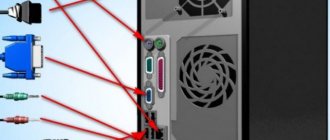
Nowadays, in almost all electronics and household appliance stores you can come across a USB device. Almost each of us has a gadget that needs such charging.
In the world of modern technology, a large number of smartphones support charging via USB. Of course, it would be easier if all gadgets had the same connector, but it’s too early to talk about this. The good news is that the socket in these chargers is the same, and you can charge different phones with one USB cable.
Now let's talk in more detail about pinouts and the features of some models.
Cable Feature
The main feature that distinguishes the wiring of a USB connector in the OTG format is that in the plug, pin 4 must be connected to pin 5. In a standard data cable, nothing is soldered to this pin at all, but this plug is called USB-BM micro. It is for this reason that you need to get to the fourth contact, and then use a jumper to connect it to the GND wire. After this procedure, the plug will be renamed USB-AM micro. It is the presence of a jumper between these contacts in the plug that allows the device to determine that some kind of peripheral device is about to be connected to it. If the device does not see this jumper, it will act as a passive device, and any flash drives connected to it will simply be completely ignored.
USB 2.0 connector pinout (types A and B)
Since the physical plugs and sockets of early versions 1.1 and 2.0 do not differ from each other, we will present the wiring of the latter.
Figure 6. Wiring the plug and socket of type A connector
Designation:
- A – nest.
- B – plug.
- 1 – power supply +5.0 V.
- 2 and 3 signal wires.
- 4 – mass.
In the figure, the coloring of the contacts is shown according to the colors of the wire, and corresponds to the accepted specification.
Now let's look at the wiring of the classic socket B.
Wiring of plug and socket type B
Designation:
- A – plug connected to the socket on peripheral devices.
- B – socket on a peripheral device.
- 1 – power contact (+5 V).
- 2 and 3 – signal contacts.
- 4 – ground wire contact.
The colors of the contacts correspond to the accepted colors of the wires in the cord.
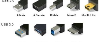
Types of USB connectors
The universal serial interface bus is represented by three types of USB connectors:
- USB 1.0 is an outdated bus, now used only for data transfer in mice and joysticks of previous versions. Low speed is due to the peculiarities of the operating mode. Low-speed and Full-speed are used here. Low-speed mode ensures data exchange at speeds of no more than 10-1500 Kbps. Full-speed mode is used to connect audio equipment and video devices.
- USB 2.0 is widely used in devices used for storing data, as well as connecting equipment that plays video. They use another High-speed mode, which increases the operating speed to 480 Mbit/s. In practice, due to the design features of the connector, this parameter does not exceed 30-35 MB/s. The structure of the socket is identical to the plug of the previous version.
- USB 3.0 differs from previous versions in high-speed information transfer. It is marked in blue on the plug contacts. The maximum data transfer speed is 5 Gbit/s. An increased amount of current up to 900 mA is used for power supply.
All three types of connectors are partially compatible with each other. When using the latest version of the bus with previous analogues, the data transfer rate is reduced. USB 3.0 is suitable for charging most peripheral devices without the use of special units.
Connecting a high-speed 3.0 type B connector to the low-end analogue is impossible. These plugs differ in the arrangement of the contacts. Connecting a USB 3.0 to a version 2.0 port is only allowed as a Type A connection.
Types of USB connectors and differences
USB is an input/output interface that eliminates the clutter associated with various peripherals that have come out in recent times. USB only recognizes one type of connector for all devices, so mixing it up is impossible. Unfortunately, in practice there are different types of connectors. And even with USB Type-C connectors, you can’t immediately tell what capabilities the cables support.
Two important aspects of usb are support capabilities and overall bandwidth. The technology supports the mode of 127 information devices and has a total throughput of at least 12 Mbit per second. Depending on the speed, there are four versions of connectors:
- 1.1 (12 or more Mbps): universal in terms of support for USB hubs, but rarely used today.
- 2.0 (480 Mbps): currently the most common and popular;
- 3.0 (5 Gbps or more): advanced specification providing fast downloads.
- 3.1 and higher (10 Gbps or more): the latest development, quite rare.
When new versions of interfaces appear, their backward compatibility is maintained - for example, 3.0 can be connected to 2.0, but not vice versa. Despite the versatility of the serial bus, there are 2 types of it:
- a socket installed on a host or device, also known as a port or socket;
- a plug attached to a cord and called a plug.
The variety of USB connectors has increased in parallel with the development of specifications. Initially, there were only mandatory standards A and B. The connectors were different, so users could not connect one to the other. Later, Method C was introduced, designed to provide a connection that was more powerful and reliable than the previous version, with increased data transfer and synchronization speeds than the first version.
Today there are the following:
| A | IN | AB | WITH |
| 2.0A | 2.0B | Micro AB | C Type (up to 10 Gbit) |
| 2.0 Micro A | 2.0 Micro B | ||
| 3.0A | mini-B (5 pin) | ||
| Mini-B (4 pin) | |||
| 3.0B | |||
| 3.0 Micro B |
Type A
Type A, found on computers and laptops, as well as on removable memory cards and many other equipment. Its scope of application is “downstream” connections to network hubs and host controllers. This is a large flat rectangular connector, the connection to which is made through a tight insert.
Type B
Another type of connector, designated B, is intended for small peripheral equipment. Externally, it has an almost regular square shape, with neat roundings at the upper corners.
Mini USB connector
USB and mini-USB are fully compatible with each other. Therefore, they can be connected using a simple adapter. Mini USB ports are mostly found on very small devices such as cameras or cell phones.
USB Mini is designed to connect modern slim mobile phones and tablets to PCs and laptops. The Mini A and B versions are equally widespread. They provide connection for miniature gadgets, and the reliability of the connection involves a construct with a special fastener.
USB micro connector
As mobile gadgets become thinner and more compact, an extremely small format, USB Micro, was developed. It exists in A and B formats, as well as an AB port.
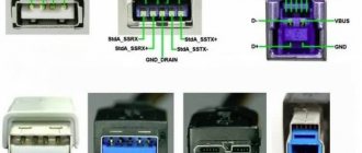
Pinout of USB type connectors.
- the first wire (red), it is supplied with a DC supply voltage of +5 V;
- the second contact (white), it is used to transmit information (D-);
- the third wire (green), it is also intended for transmitting information (D+);
- the fourth contact (black), zero supply voltage is supplied to it, it is also called the common wire.
- The first four pins are completely consistent with the 2.0 standard, so let's move on.
- The fifth pin (blue) is used to transmit information with a minus sign of USB3 (StdA_SSTX).
- The sixth pin is similar to the fifth pin, but with a plus sign (yellow).
- Seventh – additional grounding.
- The eighth pin (purple) is for receiving USB3 data (StdA_SSRX) with a minus sign.
- And finally, the last ninth (orange) is the same as the seventh pin, only with a plus sign.
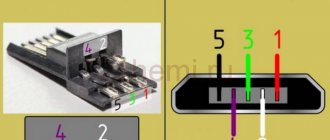
Micro USB pinout:
- the first contact (red) is intended to supply + 5 V supply voltage;
- the second and third wires (white and green) are used for data transmission;
- the fourth lilac contact in type B connectors is not used, but in type A connectors it is connected to a common wire to support the OTG function
- the last, fifth, contact (black) is supply voltage zero.
Computer technology has swept the whole world and, probably, there is no person who does not know how to use a computer. But of course, people are interested not only in the computer itself, but also in all the additional elements that change, speed up and transform the operation of such computer equipment.
Thus, recently universal USB buses, which serve as a computer interface, have become very popular. They were invented in the twentieth century, but they began to be developed only three years later. And then a new USB model appeared, which, unlike the first one, worked much better. For example, the speed of its work was increased forty times. And therefore the charge lasted longer.
But after some time, the developers of such a computer interface as USB still had low speed
in order to use external hard drives and other devices whose speed was much greater. Therefore, the creators of USB had to change the device so that a new model was obtained. Now the speed of the third type of USB has become ten times faster. Of course, this also affected charging.
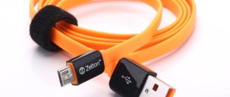
The USB cable consists of four conductors made of copper. These are two conductors intended for power supply, and the remaining conductors are in a twisted pair. This kit also includes a grounded braid.
USB cables have different physical ends. It depends on what device it is connected to. There are connections to the device itself and to the host. Moreover, USB can be with or without a cable. Another option is possible: the cable is built into the device itself. The cable is necessary to form an interface between the device and the host.
Let's now take a little look at the host. It acts as a special controller, which is programmed and controlled. Its task: to ensure the operation of the interface. By the way, the controller can most often be found in a microcircuit. A hub is required to connect the controller to other devices.
But in order to connect external devices to the hub, ports are used, at the end of which there are connectors. Cables help USB devices connect to ports. The device can be powered differently: from the bus or some kind of external power source.
It only takes a few minutes to get started and you can get started. First, the signal to start working is sent to the cable hub
, which further informs that the equipment is ready for operation.
But it is worth remembering one rule. Whenever you start pinouting a device, first determine what the pinout is on your cable. The USB connector helps you connect all external devices to your computer. This modern connection method replaces all those methods that were previously available. This connector provides additional options
: When operating computer equipment, any devices can be connected and immediately put into operation. It may also affect the charging operation.
Classification and pinout
Connectors are usually classified by type, there are only two of them:
- A is a plug connected to the female socket installed on the PC system board or USB hub. Using this type of connection, you can connect a USB flash drive, keyboard, mouse, etc. These connections are fully compatible between the initial version and the second generation. With the latest modification, compatibility is partial, that is, devices and cables from earlier versions can be connected to third-generation sockets, but not vice versa.
Type A connectors - B – plug for connecting to a socket installed on a peripheral device, for example, a printer. The dimensions of the classic type B do not allow it to be used for connecting small-sized devices (for example, tablets, mobile phones, digital cameras, etc.). To correct the situation, two standard reduced modifications of type B were adopted: mini and micro USB.
Note that such convectors are compatible only between earlier modifications.
Various Type B Connector Models
In addition, there are extension cables for the ports of this interface. At one end there is a type A plug, and at the other there is a socket for it, that is, in fact, a “female” - “male” connection. Such cords can be very useful, for example, to connect a flash drive without crawling under the table to the system unit.
USB Extension Cable
Now let's look at how contacts are wired for each of the types listed above.
HDMI cable pinout by color
The HDMI cable is divided into 5 groups of 3 cores. And 4 more wires go separately. The connector provides switching of four groups of shielded symmetrical circuits for transmitting digital video signals (aluminum foil shield), separate wires for service data and power.
| Contact number | Purpose | Wire color | Note |
| 1 | Video signal 2+ | White | Red group |
| 2 | Video signal 2 screen | Screen | |
| 3 | Video signal 2- | Red | |
| 4 | Video signal 1+ | White | Green group |
| 5 | Video signal 1 screen | Screen | |
| 6 | Video signal 1- | Green | |
| 7 | Video signal 0+ | White | Blue group |
| 8 | Video signal 0 screen | Screen | |
| 9 | Video signal 0- | Blue | |
| 10 | Tact + | White | |
| 11 | Tact screen | Screen | |
| 12 | Tact - | Brown | |
| 13 | CEC Signal | White | |
| 14 | Utility | White | Yellow group |
| 15 | Asymmetric bus signal SCL | Orange | |
| 16 | Asymmetric bus SDA signal | Yellow | |
| 17 | Earth | Screen | Yellow group |
| 18 | Power supply +5 V | Red | |
| 19 | Connection detector | Yellow | Yellow group |
There is no single color marking for cores and each cable manufacturer may have its own marking. This is exactly what was used in the test HDMI cable.
USB plug pinout
A serial bus is used to transmit data packets. It consists of 4 wires, two of which are necessary for data exchange, and the second two for power. Color pinouts are used for identification.
Conventionally, sockets are distinguished by type of tire:
- type A – power supplies, hosts and computers are connected to them;
- type B – passive, used for connecting peripheral devices;
- type C – universal, equipped with the same connectors for high-speed data exchange.
USB and mini-USB connectors are used to connect to peripheral devices. When connecting a socket to a wire, take into account the color scheme of the wiring, the type of plug and connection, the purpose and classification of the cables. The duration of the cable line depends on the correctness and quality of the connection.
Charger port classification
- SDP (Standard Downstream Ports) – data exchange and charging, allows current up to 0.5 A.
- CDP (Charging Downstream Ports) – data exchange and charging, allows current up to 1.5 A; hardware identification of the port type (enumeration) is performed before the gadget connects the data lines (D- and D+) to its USB transceiver.
- DCP (Dedicated Charging Ports) - charging only, allows current up to 1.5 A.
- ACA (Accessory Charger Adapter) - PD-OTG operation in Host mode is declared (with connection to PD peripherals - USB-Hub, mouse, keyboard, HDD and with the possibility of additional power supply), for some devices - with the ability to charge PD during OTG- sessions.
Can it be charged?
If peripherals are connected to the device via OTG, then it will have to power it, which can significantly reduce the overall operating time of the device from the built-in battery. In this regard, many people wonder whether it is possible to recharge such a device through an external source. This is possible, but this requires support for a special mode in the device, as well as a separate wiring of the USB connector for charging.
In fact, the charging mode is most often provided by modern gadget developers, but not everyone allows such a procedure. It should be noted that to switch to this charging mode, a separate USB connector wiring diagram must be used, in which the contacts are closed through a separate resistor.
Pinout of micro usb charging connector
- The USB bus connector appeared around the beginning of 1990, and its main purpose was to be used in household radio equipment. Today, the micro USB connector has become extremely popular not only in household devices, but also in professional multimedia devices. However, its “everyday” origins are clearly visible in the fact that these plug-in format connectors are installed on almost any audio-video equipment, without exception.
The first connecting connectors differed from modern ones in their large sizes, although its socket was normally installed in small-sized portable devices. Over time, the sizes of USB connectors have acquired compact forms in various variants, such as MINI-USB, MICRO-USB and simply USB. These types of connecting devices made it possible to carry out its main functional purpose. At the same time, they differed significantly in size and ease of use from the earlier created analogue.
Device and pinout of micro usb charging connector
The micro usb connecting device consists of five contact pads, an insulated mounting wire is connected to each pad. For precise orientation of the connector when connecting to the mating part of the connector, a special chamfer is made on the edge of its upper shielding part. The contact pads of the connector are numbered from one to five, which are read from right to left. For clarity, this is shown in the picture below. The wiring diagram for the micro USB connector, as well as the purpose of its contacts isolated from each other, are shown in the table:
Micro USB pinout by wire color
The shielding shell also serves as a wire, but is not soldered to a separate contact pad.
Modern connecting devices such as micro USB connectors have fairly good performance characteristics and a relatively low price. Therefore, given the availability of a huge number of different connecting wires of this type in the trade, repairs of such auxiliary equipment are carried out extremely rarely. But still, if you have to replace a defective connector socket, then pinout the micro USB connector will not cause much trouble. Structurally well-made micro USB connectors, even despite their miniature dimensions, they will not allow you to make serious mistakes in installation.
Pinout features
When talking about the pinout of a USB connector, you need to understand the symbols indicated on the diagrams. It’s worth starting with the type of connector - active (type A) or passive (type B). Using an active connector, information can be exchanged in two directions, and a passive connector only allows it to be received. You should also distinguish between two forms of connector:
- F - "mother".
- M - "dad".
USB connector
First, a few words need to be said about the compatibility of the three versions of the interface. Standards 1.1 and 2.0 are completely similar in design and differ only in the speed of information transfer. If one of the parties in the connection has a higher version, then work will be carried out at low speed. The OS will display the following message: “This device is capable of running faster.”
With compatibility between 3.0 and 2.0, everything is somewhat more complicated. A device or cable of the second version can be connected to the new connector, and backward compatibility exists only for active type A connectors. It should be noted that the USB interface allows you to supply a voltage of 5 V to the connected gadget with a current of no more than 0.5 A. For the USB standard 2.0, the color layout from left to right is as follows:
- Red - positive contact of constant voltage of 5 V.
- White - data-.
- Green - data+.
- Black is the common wire or ground.
The connector circuit is quite simple, and if necessary, repairing it will not be difficult. Since version 3.0 has increased the number of contacts, its pinout also differs from the previous standard. Thus, the color scheme of the contacts is as follows:
- Red - 5 V+.
- White - data-.
- Green - data+.
- Black is common.
- Purple - welcome.
- Orange - reception+.
- Without color - earth.
- Blue—transmission-.
- Yellow - transmission+.
Micro and mini connectors
Connectors of this form factor have five contacts, one of which is not always used. Conductors of green, black, red and white colors perform similar functions to USB 2.0. The mini-USB pinout corresponds to the micro-USB pinout. In type A connectors, the violet conductor is shorted to the black, but in passive connectors it is not used.
Miniaturization of the connector had a negative impact on reliability. Although mini-USB has a large resource, after a fairly short period of time it begins to dangle, but does not fall out of the socket. Micro-USB is a modified version of mini-USB. Thanks to the improved fastening, it turned out to be more reliable. Since 2011, this connector has become a unified standard for charging all mobile devices.
However, manufacturers are making some changes to the scheme. Thus, the pinout of the micro-USB connector for charging the iPhone involves two changes compared to the standard one. In these devices, the red and white wires are connected to the black through a resistance of 50 kOhm, and to the white - 75 kOhm. There are also differences from the standard for Samsung Galaxy smartphones. In it, the white and green conductors are closed, and pin 5 is connected to pin 4 using a 200 kOhm resistor.
Pinout diagram
Assignment of micro-USB connector contacts - socket and plug
The USB (Universal Serial Bus) connector is a universal-purpose serial bus, the most common wired method of connecting external devices to a computer. This connector allows you to organize data exchange between a computer and a video camera, card reader, MP3 player, external hard drive, or smartphone.
USB cable pinout by color
The cable description indicates its default plug orientation. The pinout is determined by the outside. If it is necessary to describe the structure from the installation side, this fact must be noted in the technical documentation. Insulating areas are marked dark gray on the connector and light gray on the metal part of the housing.
We recommend reading: Types of batteries: detailed classification of batteries by size, composition and other parameters
Purple markings are used on charging wires and DATA cables.
Pinout is necessary to identify a faulty line during repair. It indicates the purpose of a particular component.
USB 2.0 connector pinout
Since the physical plugs and sockets of early versions 1.1 and 2.0 do not differ from each other, we will present the wiring of the latter. Below is a diagram of the wiring of the plug and socket of the Type A connector:
Designations:
- A - nest.
- B - plug.
- 1 - power supply +5.0 V.
- 2 and 3 signal wires.
- 4 - mass.
In the figure, the coloring of the contacts is shown according to the colors of the wire, and corresponds to the accepted specification.
- Reobass circuit for PC
Now let's look at the wiring of the classic socket B.
Designations:
- A - plug connected to the socket on peripheral devices.
- B - socket on a peripheral device.
- 1 - power contact (+5 V).
- 2 and 3 - signal contacts.
- 4 - ground wire contact.
The colors of the contacts correspond to the accepted colors of the wires in the cord.
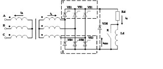
Technological structure of the USB 2.0 interface
Connectors related to products included in the specification group 1.x - 2.0 (created before 2001) are connected to a four-core electrical cable, where two conductors are power and two more are transmitting data.
Also, in specifications 1.x - 2.0, wiring of service USB connectors requires the connection of a shielding braid - in fact, a fifth conductor.
This is what the physical design of normal USB connectors belonging to the second specification looks like. On the left are the “male” type versions, on the right are the “female” type versions and the pinout corresponding to both options
Existing versions of universal serial bus connectors of the noted specifications are presented in three options:
- Normal – type “A” and “B”.
- Mini – type “A” and “B”.
- Micro – type “A” and “B”.
The difference between all three types of products lies in the design approach. If normal connectors are intended for use on stationary equipment, “mini” and “micro” connectors are made for use in mobile devices.
This is what the physical design of the connectors of the second specification from the “mini” series looks like and, accordingly, the label for Mini USB connectors - the so-called pinout, based on which the user makes the cable connection
Therefore, the last two types are characterized by a miniature design and a slightly modified connector shape.
Pinout table for standard type “A” and “B” connectors
| Contact | Specification | Cable conductor | Function |
| 1 | Power + | Red (orange) | + 5V |
| 2 | Data - | White (gold) | Data – |
| 3 | Data + | Green | Data + |
| 4 | Nutrition - | Black blue) | Earth |
Along with the execution of connectors of the “mini-A” and “mini-B” types, as well as connectors of the “micro-A” and “micro-B” types, there are modifications of the “mini-AB” and “micro-AB” type connectors.
A distinctive feature of such designs is the wiring of the USB conductors on a 10-pin pad. However, in practice, such connectors are rarely used.
Micro USB and Mini USB interface pinout table for type “A” and “B” connectors
| Contact | Specification | Cable conductor | Function |
| 1 | Power + | Red | + 5V |
| 2 | Data - | White | Data – |
| 3 | Data + | Green | Data + |
| 4 | Identifier | – | Host - device |
| 5 | Nutrition - | Black | Earth |
Connector diagram for USB 2.0
In the diagram you can see several connectors that differ from each other according to a certain characteristic. For example, an active (power) device is designated by the letter A, and a passive (connected) device is designated by the letter B. Active devices include computers and hosts, while passive devices include printers, scanners, and other devices. It is also customary to separate connectors by gender: M (male) or “male” is the plug, and F (female) or “female” is the connector socket. There are formats by size: mini, micro and without marking. For example, if you see the designation “USB micro-VM”, this means that the plug is designed to connect to a passive device in micro format.
We recommend reading: DIY generator voltage regulator relay: diagram
To pin out sockets and plugs, you will need knowledge about the purpose of the wires in a USB cable:
- The red VBUS (“plus”) carries a constant voltage of 5 Volts relative to GND. The minimum electric current value for it is 500 mA;
- the white wire is connected to the negative (D-);
- the green wire is attached to the “plus” (D+);
- The black color of the wire means that the voltage in it is 0 Volts, it carries a negative charge and is used for grounding.
In mini and micro formats, connectors contain five contacts each: red, black, white and green wires, as well as ID (which in connectors of type A is shorted to GND, and in connectors B is not used at all).
Sometimes you can find a bare Shield wire in the USB cable. This wire has no number.
If you use a table in your work, the connector in it is shown from the outside (working) side. The insulating parts of the connector are light gray, the metal parts are dark gray, and the cavities are marked white.
In order to carry out the correct USB wiring, you need to mirror the image of the front part of the connector.
Connectors for mini and micro USB formats consist of five contacts. Therefore, the fourth contact in type B connectors will not have to be used in operation. This contact in type A connectors is connected to GND, and the fifth is used for GND itself.
As a result of some simple manipulations, you can independently make pinouts for USB ports of different formats.
USB wiring version 3.0 is distinguished by the addition of four colored wires and additional grounding. Due to this, the USB 3.0 cable is noticeably thicker than its younger brother.
Schemes for connecting USB devices to each other and wiring the device plugs:
- PS/2 To USB port
- Joystick Defender Game Racer Turbo USB-AM
- Wiring usb am and micro usb bm, for charging and transferring data to a computer
- USB-OTG
- USB wiring SAMSUNG GALAXY TAB 2
Pinout of USB 3.0 connectors (types A and B)
In the third generation, peripheral devices are connected via 10 (9 if there is no shielding braid) wires; accordingly, the number of contacts is also increased. However, they are located in such a way that it is possible to connect devices of earlier generations. That is, the +5.0 V contacts, GND, D+ and D-, are located in the same way as in the previous version. The wiring for Type A socket is shown in the figure below. Designations:
- A - plug.
- B - nest.
- 1, 2, 3, 4 - connectors fully correspond to the pinout of the plug for the USB 2.0 type B version, the colors of the wires also match.
- 5 (SS_TX-) and 6 (SS_TX+) connectors for data transmission wires via the SUPER_SPEED protocol.
- 7 - ground (GND) for signal wires.
- 8 (SS_RX-) and 9 (SS_RX+) connectors of wires for receiving data via the SUPER_SPEED protocol.
The colors in the figure correspond to those generally accepted for this standard. As mentioned above, a plug from an earlier model can be inserted into the socket of this port; accordingly, the throughput will decrease. As for the plug of the third generation of the universal bus, it is impossible to insert it into the sockets of the early release.
- Maybe,
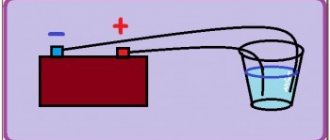
Charging the battery via Micro USB
In addition, it supplies a 5-volt power supply to charge the battery of wearable gadgets. Since almost all modern lithium batteries have an operating voltage of 3.7 V, the 5 V supplied via Micro-USB is excellent for replenishing energy. True, not directly to the battery, but through the charger converter.
I’m glad that the connector pinout is the same for all smartphone manufacturers - Samsung, LG, Huaway and others. Thus, a 220 V charger-adapter from one phone is most often suitable for charging another without changing the pinout.
The main advantage of the Micro-USB connector over other types is the ability to connect Plug&Play devices without the need to restart the computer or manually install drivers. Devices can be connected while the computer is running and disconnected without having to press any buttons.
Conductor colors
There are relatively few flowers. Also in the diagram there may be a group of wires that will be marked with the same color.
Let's start with something simple - there are only four colors in the USB 2.0 pinout:
- This conductor is red - it is to it that DC voltage is supplied.
- The second white conductor is needed to transmit information via USB.
- The green conductor is also needed for data transfer.
- The black conductor is supplied with zero supply voltage. It is also called the common (or main) wire, and is designated by the “Ʇ” icon.
In other cases, there may be significantly more colors and wires. For example, in circuit 3.0 there will already be 9 conductors.
Also, do not forget that some developers like to make their own changes to standard schemes.
Types of connectors
The types of USB connectors depend on the function performed and the speed at which data is transferred. Thanks to the existence of several types of USB connectors, extended functionality is covered, which allows the user to simplify the connection between the computer and the device (mouse, keyboard, iPad, MFP, scanner, etc.).
When choosing a USB, you need to pay attention to the type of USB cable, the function and transfer speed
Type-A
This USB connector still ranks among other types. The user encounters such cables every day. These include storage devices (flash drives), USB cables from chargers. Most cameras and routers are equipped with this type of USB cable. It is reliable and safe to use. It is harder to break and disable it.
This type is equipped with a built-in security system. The cable can only be inserted into the computer on one side. If you turn the cord over, it simply will not fit into the connector. Which is an advantage. Especially when using the cable by inexperienced users.
Type-B
Type B is used to connect peripherals - MFPs, scanners, faxes, and so on. A type B cable is not always supplied with the device and often you have to purchase it yourself. There are 2 types of USB type b cables: micro- and mini-USB.
A type of mini USB is an outdated USB port. This is an early version of the micro type. The use of mini USB is kept to a minimum. But still, sometimes there are devices that use this type of connection. You can see what micro USB looks like in the photo.
Micro USB connector type B is a smaller version of connector b (there is a similar type of connector A - Micro USB Type A). Micro USB connector is used in most mobile devices (except Apple). Apple has its own connector.
Type-C
It was invented relatively recently (first appeared on the market in 2014). The USB Type C connector is at the beginning of its development and is not actively used. Has reduced dimensions of both inputs. First used by Apple, which continues to improve this development today.
Micro-USB 3.0 pinout |
This article will show the pinout (wiring) of micro-USB 3.0. In addition, we will analyze all the contacts (pins) of this connector, as well as their colors and purpose. There is no need to explain that the micro-USB 3.0 connector is a modification of the USB 3.0 connector. Each connector pin has the same purpose as in USB 3.0. Each wire with this assignment is the same color as the base USB 3.0 connector. However, this is not just a singular connector. There are several types of connector with one common name micro-USB 3.0. They differ not only in wiring, but also in shape. Their designations are also different. Let's start looking at the micro USB 3.0 pinout with the USB 3.0 Micro-B connector (plug).
USB 3.0 Micro B pinout in color
The picture below shows the main component, but it is not the only one. Looking at it, it’s easy to guess that it is noticeably different from micro-USB 3.0. This is not only an additional number of wires and contacts, but also the shape itself. You can already understand that such a connector cannot be inserted into a micro-USB 2.0 socket. Pins 1, 2, 3, 5 have the same purpose and match the colors of the micro-USB 2.0 pins. As for the remaining contacts, they are used for high-speed data transmission and reception (SuperSpeed). The colors in the picture match the standard colors in reality. The table contains not only the colors of the wires and their purpose, but also the name.
USB 3.0 Micro B Pin Chart
| Description | Wire color | Name | Conclusion |
| 5V+ | Red | VBUS | 1 |
| Data - | White | D— | 2 |
| Data + | Green | D+ | 3 |
| OTG | — | ID | 4 |
| General | Black | GND | 5 |
| Transfer - | Blue | StdB SSTX— | 6 |
| Transfer + | Yellow | StdB SSTX+ | 7 |
| Earth | Earth | GND DRAIN | 8 |
| Reception - | Violet | StdB SSRX - | 9 |
| Reception + | Orange | StdB SSRX+ | 10 |
If you compare the USB 3.0 Micro B pinout with the USB 3.0 pinout, you will notice that one more pin has been added. In all types of connectors, pin No. 4 (pin) is responsible for identifying devices that can connect to each other without the participation of a computer (on the go). The question inevitably arises that since there is USB 3.0 Micro-B, then there must also be a USB 3.0 Micro-A connector. Is there such a type of connector, and how does it differ from USB 3.0 Micro-B? Let’s find out now.
What is the difference between USB 3.0 Micro B and USB 3.0 Micro A
The figure below shows both types of USB 3.0 Micro “plugs” and even with dimensions. As can be seen from the figure, the main difference is the shape of the connector. USB 3.0 Micro B has more cut edges than USB 3.0 Micro A. Therefore, the USB 3.0 Micro A plug cannot be inserted into any micro-USB 3.0 socket.
Now about the fourth contact (ID). It is worth adding that the fourth contact (pin) in the USB 3.0 Micro B connector is not used. But it's in a Micro-B plug. In sockets, pin #4 will be used for host/client mode. Also, the table does not indicate the Shell, which is the shield of the connector, but this goes without saying...
USB 3.0 Micro B socket pinout in color
Having dealt with the plugs, we move on to the micro-USB 3.0 sockets. First, let's look at the USB 3.0 Micro B socket. It is more truncated in the sense that it will not be possible to insert a USB 3.0 Micro A plug into it. The colors and assignments of the contacts on the socket are the same as those on the USB 3.0 Micro B plug. True, it’s not surprising for some reason... Most likely because these are two parts of one whole, and one is inserted into the other. But even though the Ukrainian night is quiet, the sign is still placed under the picture.
USB 3.0 Micro B socket pin chart
| Description | Wire color | Name | Conclusion |
| 5V+ | Red | VBUS | 1 |
| USB 2.0 data | White | D— | 2 |
| Green | D+ | 3 | |
| OTG | — | ID | 4 |
| General | Black | GND | 5 |
| Super Speed transmission (+ and -) | Blue | StdA SSTX— | 6 |
| Yellow | StdA SSTX+ | 7 | |
| Earth | Earth | GND DRAIN | 8 |
| Super Speed reception | Violet | StdA SSRX - | 9 |
| Orange | StdA SSRX+ | 10 |
USB 3.0 Micro AB socket pinout
It’s already clear from the name that the USB 3.0 micro-AB socket is universal, as it fits both plugs (Micro-A and Micro-B). Mobile devices will be equipped with such a socket. I think that there is no point in posting a table, since the only difference in wiring is the ID pin (4). Therefore, we will limit ourselves to only a visual drawing, so that it is clear that both plugs (Micro-A and Micro-B) can be inserted into this device. However, it is worth adding that this type of connector is used only if the device supports the On-The-Go (OTG) standard. This socket can be used not only to connect USB 3.0 Micro-A and USB 3.0 Micro-B connectors, but also connectors such as USB 2.0 Micro-A or USB 2.0 Micro-B. Well, it’s clear that USB 3.0 Micro plugs will not fit into the USB 2.0 Micro-AB female connector. Now, knowing the pinout (pinout) of micro-USB 3.0, as well as all other types of USB 3.0 pinout, you can safely start making (or repairing) all kinds of USB 3.0 adapters. This is what we will be doing in the near future. Success in creative work!
How to solder a connector. USB2.0 and USB3.0 wiring by color (micro and mini connectors)
The pin assignments of the USB plug are clearly defined, see. A very useful site, where it is simple and accessible in normal Russian language, black and white, it is explained in detail what and where to solder. It simply couldn’t be simpler, before soldering, let’s turn on our brains, because that’s what they’re given to us for, take a piece of paper and draw a simple diagram. If the required pinout is not here, it doesn’t matter - for this there is the vast and powerful Internet, where you can find everything you need by the name of the company. The guys who share their knowledge have great respect and respect, well done!!
Micro/mini USB pinout
The smaller ports are five-pin. Micro is the standard for most gadgets. They are distinguished by their miniature dimensions; mini, as mentioned above, is becoming obsolete. Both options have the same pinout, which is presented in the table below.
On a note. The designation of such ports is as follows: “mother” is micro-AF (BF), and “male” is micro-AM (VM).
| Contact | Color | Purpose |
| 1 | red | to supply +5V supply voltage |
| 2 | white | for data transfer |
| 3 | green | |
| 4 | lilac | closes to common wire to support OTG function |
| 5 | black | supply voltage zero |
The additional shielding connector is not found everywhere and therefore does not have a number.
Note: contact No. 4 in the B type is not used.
Useful: How to connect a system unit and a TV - 6 connection options
Features of cable wiring on connector contacts
There are no special technological nuances associated with soldering cable conductors on the contact pads of connectors. The main thing in this process is to ensure that the color of the pre-insulated cable conductors matches the specific contact (pin).
Color coding of conductors inside the cable assembly used for USB interfaces. Shown from top to bottom, respectively, is the color scheme of cable conductors for specifications 2.0, 3.0 and 3.1
Also, if you are wiring modifications of outdated versions, you should take into account the configuration of the connectors, the so-called “male” and “female”.
The conductor soldered on the male contact must match the soldering on the female contact. Take, for example, the option of wiring the cable to USB 2.0 pins.
The four working conductors used in this embodiment are usually marked in four different colors:
- red;
- white;
- green;
- black.
Accordingly, each conductor is soldered onto a pad marked with a connector specification of a similar color. This approach greatly simplifies the work of the electronics engineer and eliminates possible errors during the desoldering process.
A similar soldering technology is applied to connectors of other series. The only difference in such cases is the larger number of conductors that have to be soldered. To simplify your work, it is convenient to use special tools - a reliable soldering iron for soldering wires at home and a stripper for removing insulation from the ends of the wires.
Regardless of the connector configuration, screen conductor soldering is always used. This conductor is soldered to the corresponding contact on the connector, Shield - protective screen .
There are frequent cases of ignoring the protective screen, when “experts” do not see the point in this conductor. However, the lack of a screen dramatically reduces the performance of the USB cable.
Therefore, it is not surprising when, with a significant length of cable without a screen, the user experiences problems in the form of interference.
Wiring the connector with two conductors to organize a power line for the donor device. In practice, different wiring options are used, based on technical needs.
There are different options for soldering a USB cable, depending on the configuration of the port lines on a particular device.
For example, to connect one device to another in order to obtain only a supply voltage (5V), it is enough to solder only two lines on the corresponding pins (contacts).
Now let's move on to the USB 3.0 port
The second name for a USB 3.0 port is USB Super Speed, due to the increased data transfer speed of up to 5 Gb/sec. To increase speed indicators, engineers used full-duplex (two-wire) transmission of both sent and received data. Due to this, 4 additional contacts appeared in the connector -/+ StdA_SSRX and -/+StdA_SSTX. In addition, increased speeds required the use of a new type of controller with higher power consumption, which led to the need to use additional power pins in the USB 3.0 connector (DPWR and DGND). The new type of connector began to be called USB Powered B. In a digression, let’s say that the first Chinese flash drives for this connector were made in cases without taking into account the thermal characteristics of their controllers and, as a result, they got very hot and failed.
The practical implementation of the USB 3.0 port made it possible to achieve a data exchange rate of 380 MB/sec. For comparison, the SATA II port (connecting hard drives) is capable of transferring data at a speed of 250 MB/sec. The use of additional power allowed the use of devices with a maximum current consumption of up to 900mA on the socket. This way, either one device or up to 6 gadgets with a consumption of 150mA can be connected. In this case, the minimum operating voltage of the connected device can be reduced to 4V. Due to the increased power of the connector, engineers had to limit the length of the USB 3.0 cable to 3 m, which is an undoubted disadvantage of this port. Below we provide the standard USB 3.0 port specification
The pinout of the USB 3.0 connector is as follows:
Operating systems starting with Windows 8, MacBook Air and MacBook Pro latest versions and Linux with kernel version 2.6.31 have full software support for the USB 3.0 specification. Due to the use of two additional power contacts in the USB 3.0 Powered-B connector, it is possible to connect devices with a load capacity of up to 1A.
Universal Serial Bus (USB) wiring diagram
Conclusions and useful video on the topic
The video below explains the main points of pinout of connectors of the 2.0 series and others, and visually explains individual details of the production of soldering procedures.
Having complete information on the pinout of Universal Serial Bus connectors, you can always cope with a technical problem associated with conductor defects. This information will also come in handy if you need to connect some digital devices in a non-standard way.
Would you like to supplement the above material with useful comments or valuable tips on do-it-yourself desoldering? Write comments in the block below, add, if necessary, unique photographic materials.
Maybe you still have questions after reading the article? Ask them here - our experts and competent site visitors will try to clarify unclear points.