Operating principle of capacitors
When a circuit is connected to an electrical source, electrical current begins to flow through the capacitor. At the beginning of the passage of current through the capacitor, its strength is at its maximum and the voltage is at its minimum. As the device accumulates charge, the current drops until it disappears completely, and the voltage increases.
During the process of charge accumulation, electrons accumulate on one plate and positive ions on the other. Charge does not flow between the plates due to the presence of a dielectric. This is how the device accumulates charge. This phenomenon is called the accumulation of electric charges, and the capacitor is called an electric field accumulator.
Distance between plates
The capacitance of a capacitor is inversely proportional to the distance between the plates. In order to explain the nature of the influence of this factor, it is necessary to recall the mechanics of the interaction of charges in space (electrostatics).
If the capacitor is not in an electrical circuit, then the charged particles located on its plates are influenced by two forces. The first is the repulsive force between like charges of neighboring particles on the same plate. The second is the force of attraction of opposite charges between particles located on opposite plates. It turns out that the closer the plates are to each other, the greater the total force of attraction between charges with the opposite sign, and the more charge can be placed on one plate.
Capacitor design
The designs of modern capacitors are varied, but several typical options can be distinguished:
Batch design
Used in glass-enamel, ceramic and glass-ceramic capacitors. The packages are formed by alternating layers of plates and dielectric. The covers can be made of foil, or they can be layers on dielectric plates - sprayed or applied by burning.
Each stack capacitor has upper and lower plates that have contacts at the ends of the stack. Terminals are made of wire or tape strips. The package is pressed, sealed, and covered with protective enamel.
Tubular design
High-frequency capacitors can have this design. They are a ceramic tube with a wall thickness of 0.25 mm. A silver conductive layer is applied to its outer and inner sides by burning in. The outside of the part is treated with an insulating substance. The inner lining is brought out onto the outer layer to attach a flexible lead to it.
Disc design
This design, like the tubular one, is used in the manufacture of high-frequency capacitors.
The dielectric in disk capacitors is a ceramic disk. Silver plates are burned onto it, to which flexible leads are connected.
Cast sectional construction
It is used in monolithic multilayer ceramic capacitors used in modern equipment, including integrated circuits. A part with 2 grooves is made by casting ceramics. The grooves are filled with silver paste, which is secured using the implantation method. Flexible leads are soldered to the silver inserts.
Roll design
Characteristic of paper film low-frequency capacitors with high capacity. Paper tape and metal foil are rolled into a roll. In metal-paper capacitors, a metal layer up to 1 micron thick is applied to the paper tape.
Story
The prototype of the first capacitor was the “Leyden jar,” invented in 1745. It was a glass jar in which the linings were thin sheets of tin foil glued to the inside and outside of the walls. The experimenter’s hands could act as the outer covering, and the liquid could serve as the inner covering.
Leyden jar
Note! The first electric shock from a capacitor discharge was obtained when testing a Leyden jar with palms instead of the outer lining.
Where are capacitors used?
Capacitors are used in almost all modern devices: subwoofers, electric motors, cars, pumps, power tools, air conditioners, refrigerators, mobile phones, etc.
Depending on the functions performed, they are divided into general purpose and highly specialized.
General purpose capacitors include low-voltage storage devices that are used in most types of electrical equipment.
Highly specialized ones include high-voltage, pulse, noise suppression, dosimetric and start-up capacitors.
Behavior of a capacitor in DC and AC circuits
In DC circuits, a charged capacitor forms a gap that prevents the flow of current. If voltage is applied to the plates of a discharged part, current will flow. In this case, the capacitor will charge, the current will drop, and the voltage on the plates will increase. When the voltage on the plates and the power supply is equal, the current flow stops.
With constant voltage, the capacitor holds a charge when the power is on. After switching off, the charge is discharged through the loads present in the circuit.
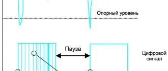
A charged capacitor also does not allow alternating current to pass through. But during one period of the sinusoid, the storage device is charged and discharged twice, so the current is able to flow through the capacitor during its discharge period.
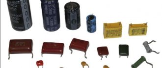
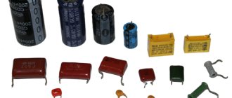
Types and classification of capacitors
Different types of capacitors are adapted to different operating conditions, are aimed at performing specific tasks and have various side effects.
The main feature by which a capacitor is classified is the type of dielectric. It is the dielectric material that determines many of the characteristics of a capacitor.
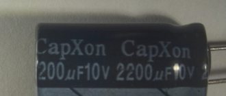
Electrolytic capacitors
In electrolytic capacitors, the anode is a metal plate, the dielectric is an oxide film, and the cathode is a solid, liquid or gel-like electrolyte. The presence of a gel-like electrolyte makes the device polar, meaning current can only flow through it in one direction. Representatives of this family are aluminum and tantalum capacitors.
Aluminum electrolytic capacitors have a capacity from 0.1 to several thousand microfarads. They are usually used at audio frequencies. The electrochemical cell is tightly packed, which provides high effective inductance, which prevents the use of aluminum storage devices at ultra-high frequencies.
In tantalum capacitors, the cathode is made of manganese dioxide. The combination of the significant surface area of the anode and the dielectric characteristics of tantalum oxide provides a high specific capacitance (capacitance per unit volume or mass of the dielectric). This means that tantalum capacitors are much more compact than aluminum capacitors of the same capacity.
Tantalum capacitors have their disadvantages. Devices of early generations are prone to failures and fires are possible. They can occur when too high an inrush current is applied, which changes the structural state of the dielectric. The fact is that tantalum oxide in an amorphous state is a good dielectric. When a large inrush current is applied, tantalum oxide changes from an amorphous state to a crystalline state and turns into a conductor. Crystalline tantalum oxide further increases the current strength, which leads to fire. Modern tantalum capacitors are produced using advanced technologies and practically do not fail, do not swell, and do not catch fire.
Film and metal film capacitors
Film capacitors have a dielectric layer of polymer film located between layers of metal foil.
Such devices have a small capacitance (from 100 pF to several μF), but can operate at high voltages - up to 1000 V.
There is a whole family of film capacitors, but all types are characterized by small capacitance and inductance. Due to their low inductance, these devices are used in high-frequency circuits.
The main differences between capacitors with different types of films:
- Capacitors with a dielectric in the form of a polypropylene film are used in circuits that place high demands on temperature and frequency stability. They are suitable for power supply systems, EMI suppression.
- Capacitors with a dielectric in the form of a polyester film are low cost and can withstand high temperatures when soldering. Frequency stability, compared to polypropylene types, is lower.
- Capacitors with a dielectric made of polycarbonate and polystyrene film, which were used in old circuits, are no longer relevant today.
Ceramic capacitors
Ceramic capacitors use ceramic plates as the dielectric.
Ceramic capacitors have a small capacitance - from one pF to several tens of microfarads.
Ceramics have a piezoelectric effect (the ability of a dielectric to polarize under mechanical stress), so some types of these capacitors have a microphonic effect. This is an undesirable phenomenon in which part of the electrical circuit picks up vibrations, like a microphone, which causes interference.
Paper and metal-paper capacitors
Paper, often oiled, is used as a dielectric in these capacitors. Devices with oiled paper are larger in size. Models with non-oiled paper are more compact, but they have a significant drawback - they increase energy losses under the influence of moisture, even in sealed packaging. Lately, these parts are rarely used.
More information about types and analogues of capacitors
What do they consist of?
Larger capacities can only be achieved using chemical sources.
Electrolytic capacitors are very close to chemical current sources. They, like batteries, have a cathode, anode and electrolyte. And also the same disadvantages as batteries.
Therefore, such capacitors are called electrolytic. Among radio amateurs and electronics engineers, they are abbreviated as electrolytes.
According to the composition of the electrolyte, they are of liquid and dry type. There are also oxide-semiconductor and oxide-metallic ones.
They are indicated on circuit diagrams in the same way as a regular one, but only with the polarity indicated in the form of a + sign.
Basic parameters of capacitors
Capacity
This indicator characterizes the capacitor's ability to accumulate electrical charge. The larger the area of the conductor plates and the smaller the thickness of the dielectric layer, the larger the capacitance. This characteristic also depends on the dielectric material. The device indicates the nominal capacity. The actual capacity, depending on operating conditions, may differ from the nominal capacity within significant limits. Standard options for nominal capacity range from units of picofarads to several thousand microfarads. Some models may have a capacity of several tens of farads.
Classic capacitors have a positive capacitance, that is, the greater the applied voltage, the greater the accumulated charge. But today, devices with unique properties, which scientists call “anti-capacitors,” are under development. They have negative capacitance, that is, as the voltage increases, their charge decreases, and vice versa. The introduction of such anti-capacitors into the electronics industry will speed up the operation of computers and reduce the risk of overheating.
What happens if you install a drive with a larger/smaller capacity than required? If we are talking about smoothing out voltage ripples in power supplies, then installing a capacitor with a capacitance exceeding the required value (within reasonable limits - up to 90% of the nominal value) in most cases improves the situation. Installing a capacitor with a smaller capacitance may degrade the performance of the circuit. In other cases, the possibility of installing a part with parameters different from the specified ones is determined specifically for each case.
Specific capacitance
The ratio of the nominal capacitance to the volume (or mass) of the dielectric. The thinner the dielectric layer, the higher the specific capacitance, but the lower its breakdown voltage.
Energy Density
This concept refers to electrolytic capacitors. The maximum density is typical for large capacitors, in which the mass of the housing is significantly lower than the mass of the plates and electrolyte.
Rated voltage
Its value is reflected on the housing and characterizes the voltage at which the capacitor operates during its service life with parameters fluctuating within specified limits. The operating voltage must not exceed the rated value. For many capacitors, the rated voltage decreases as the temperature increases.
Polarity
Polar capacitors are electrolytic capacitors that have positive and negative charges. On domestically produced devices, a “+” sign was usually placed at the positive electrode. On imported devices, a negative electrode is indicated, next to which there is a “-” sign. Such capacitors can perform their functions only if the voltage polarity is connected correctly. This fact is explained by the chemical features of the reaction of the electrolyte with the dielectric.
What happens if you reverse the polarity of a capacitor? Usually in this case the devices fail. This occurs due to the chemical destruction of the dielectric, which causes an increase in current strength, boiling of the electrolyte and, as a result, swelling of the housing and a possible explosion.
Most charge storage devices belong to the group of non-polar capacitors. These parts ensure correct operation no matter how the pins are connected to the circuit.
Capacitance of a solitary conductor
Let us assume that the charged conductor is located so far from all other bodies that the interaction of the charges of the conductor with surrounding bodies can be ignored. In this case, the conductor is called solitary.
The potential of all points of our conductor, as we know, has the same value, which is called the potential of the conductor. It turns out that the potential of a solitary conductor is directly proportional to its charge. The proportionality coefficient is usually denoted by , so
The quantity is called the electrical capacitance of the conductor and is equal to the ratio of the charge of the conductor to its potential:
(1)
For example, the potential of a solitary sphere in a vacuum is equal to:
where is the charge of the ball and is its radius. Hence the capacity of the ball:
(2)
If the ball is surrounded by a dielectric medium with dielectric constant , then its potential decreases by a factor of:
Accordingly, the capacity of the ball increases by several times:
(3)
The increase in capacitance in the presence of a dielectric is the most important fact. We will meet him again when considering capacitors.
From formulas (2) and (3) we see that the capacity of the ball depends only on its radius and the dielectric constant of the environment. The same will happen in the general case: the capacitance of an isolated conductor does not depend on its charge; it is determined only by the size and shape of the conductor, as well as the dielectric constant of the medium surrounding the conductor. Capacitance also does not depend on the conductor substance.
What is the meaning of the concept of capacity? The capacitance shows how much charge needs to be imparted to the conductor in order to increase its potential by V. The greater the capacitance, the correspondingly more charge must be placed on the conductor for this.
The unit of measurement for capacitance is farad (F). From the definition of capacity (1) it is clear that Ф = C/V.
For fun, let's calculate the capacity of the globe (it is a conductor!). We consider the radius to be approximately equal to km.
µF.
As you can see, F is a very large capacity.
The unit of measurement of capacitance is also useful because it allows you to greatly save on the designation of the dimension of the dielectric constant. In fact, let us express from formula (2):
Therefore, the dielectric constant can be measured in F/m:
F.
It's easier to remember that way, isn't it?
Parasitic parameters of capacitors
Capacitors, in addition to their main characteristics, have so-called “parasitic parameters” that distort the operating properties of the oscillating circuit. They must be taken into account when designing the circuit.
These parameters include their own resistance and inductance, which are divided into the following components:
- Electrical insulation resistance (r), which is determined by the formula: r = U/Iout, in which U is the power source voltage, Iout is the leakage current.
- Equivalent series resistance (ESR). This value depends on the electrical resistance of the material of the plates, leads, contacts between them, and losses in the dielectric layer. The ESR increases with increasing frequency of the current supplied to the storage device. In most cases, this characteristic is not important. The exception is electrolytic storage devices installed in the filters of switching power supplies.
- Equivalent series inductance - L. At low frequencies, this parameter, due to the self-inductance of the plates and leads, is not taken into account.
Parasitic parameters also include Vloss - an insignificant value expressed as a percentage, which shows how much the voltage drops immediately after the capacitor stops charging.
Relative dielectric constant
An equally significant factor influencing the capacitance of a capacitor is the property of the material between the plates as the relative dielectric constant ɛ. This is a dimensionless physical quantity that shows how many times the force of interaction between two free charges in a dielectric is less than in a vacuum.
Materials with a higher dielectric constant allow for greater capacitance. This is explained by the polarization effect - the displacement of the electrons of the dielectric atoms towards the positively charged capacitor plate.
Polarization creates an internal electric field in the dielectric, which weakens the overall potential (voltage) difference of the capacitor. Voltage U prevents the flow of charge Q to the capacitor. Therefore, lowering the voltage helps place more electrical charge on the capacitor.
Below are examples of dielectric constant values for some insulating materials used in capacitors.
- Air – 1.0005
- Paper – from 2.5 to 3.5
- Glass – from 3 to 10
- Mica – from 5 to 7
- Metal oxide powders – from 6 to 20
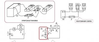
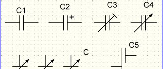
Designation of capacitors in the diagram
In the drawings, a capacitor with a constant capacitance is indicated by two parallel lines - plates. They are signed with the letter "C". Next to the letter they put the serial number of the element on the diagram and the capacitance value in pF or µF.
In variable capacitors, parallel lines are crossed out by a diagonal line with an arrow. Tuning models are indicated by two parallel lines crossed out by a diagonal line with a dash at the end. The designation of polar capacitors indicates a positively charged plate.
| Fixed capacitor |
| Polarized (polar) capacitor |
| Variable capacitor tuning capacitor |
| Varicap |
Features of connecting several capacitors in a circuit
The connection of several capacitors to each other can be series or parallel.
Sequential
A series connection allows you to apply more voltage to the plates than to a separate part. The voltage is distributed depending on the capacity of each drive. If the capacitances of the parts are equal, then the voltage is distributed equally.
The resulting capacitance in such a circuit is found by the formula:
Commun = 1/(1/С1+1/С2…+1/Сn)
If you carry out calculations, it will become clear that an increase in voltage in the circuit is achieved by a significant drop in capacitance. For example, if two 10 µF capacitors are connected in series in a circuit, the total capacitance will be only 5 µF.
Parallel
This is the most common method in practice to increase the total capacitance in the circuit. A parallel connection allows you to create one large capacitor with the total area of the conducting plates. The total capacity of the system is the sum of the capacities of the connected parts.
C total = C1+C2+…+Cn
The voltage on all elements will be the same.
Video
Coffee capsules Nescafe Dolce Gusto Cappuccino, 8 servings (16 capsules)
435 ₽ More details
Coffee capsule Nescafe Dolce Gusto Cafe O Le Coffee with milk, 3 packs of 16 capsules each
1305 ₽ More details
IP cameras
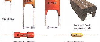
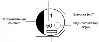
Capacitor markings
The marking of a capacitor, regardless of its type, contains two mandatory parameters - capacitance and rated voltage. The most common digital marking indicates the resistance value. It uses three or four digits.
Briefly, the essence of the three-digit marking: the first two digits on the left indicate the capacitance value in picofarads. The rightmost number shows how many zeros should be added to the numbers on the left. The result is obtained in picofarads. Example: 154 = 15x104 pF. On foreign-made capacitors, pF are designated as mmf.
In a four-digit code, the capacitance in picofarads is indicated by the first three digits, and the fourth indicates the number of zeros to be added. For example: 2353=235x103 pF.
To designate the capacity, alphanumeric markings containing the letter R can also be used, which indicates the location of the decimal point. For example, 0R8=0.8 pF.
On the case, the voltage value is indicated by a number followed by the letters: V, WV (which means “operating voltage”). If there is no indication of the permissible voltage, then the capacitor can only be used in low-voltage circuits.
In addition to capacitance and voltage, other characteristics of the part may be indicated on the case:
- Dielectric material. B – paper, C – mica, K – ceramics.
- Degree of protection from external influences. G – hermetically sealed design, O – pressed housing.
- Design. M – monolith, B – barrel, D – disk, C – sectional version.
- Current mode. I – pulsed, U – universal, CH – direct current only, P – alternating/direct.
Use of asynchronous motors
Three-phase and single-phase asynchronous motors are actively used in various sectors of the economy. There are several reasons for this:
- Simplicity of design.
- Reliability and durability during use.
- In order to start the engine, there is no need to use expensive and scarce devices.
- The motor does not require too frequent maintenance.
By appearance, you can easily distinguish three-phase motors from single-phase ones. The former always have 6 terminals, while the latter have two or four.
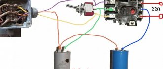
For three-phase motors, the windings are connected in two ways: star or delta. They assume the use of a voltage of 380 volts. However, it is rarely used in everyday life. To use such a motor, you need to know how to connect it correctly.
This is done using a phase-shifting capacitor. This will allow the use of three-phase motors when connected to a single-phase network. In this case, the motor power will be equal to 50% -60% of the nominal.
Checking the starting capacitor Source antemion.ru
Optimal operation of a three-phase motor is ensured by using a variable capacitance. To do this, at the first stage, working and starting capacitors are used, and at the second, only the first of them.
Asynchronous single-phase motors are often used in everyday life. Additional winding is usually required to start.
When choosing the capacitance of a capacitor, it is necessary to take into account how the magnitude of the starting torque depends on it. As this characteristic increases, the force increases. At a certain value it becomes maximum. After a further increase, the starting torque will begin to fall.
Calculation of capacitor parameters Source uk-energotekhservis.rf
How to check the performance of a capacitor
To check the capacitor for functionality, use a multimeter. Before checking the drive, it is necessary to determine which device is located in the circuit - polar (electrolytic) or non-polar.
Checking the polar capacitor
When checking a polar capacitor, it is necessary to observe the correct polarity of connecting the probes: the positive one must be pressed against the positive leg, the negative one against the minus leg. If you reverse the polarity, the capacitor will fail.
After desoldering the parts, it is placed in free space. The multimeter is switched on to the resistance measurement mode (“diagnosis”).
Use probes to touch the terminals of the device, observing polarity. The correct situation is when the first value appears on the display and begins to gradually increase. The maximum value that must be achieved for a working device is 1. If you just touched the leads with the probes and the number 1 immediately appears on the screen, it means the device is faulty. The appearance of “0” on the screen means that a short circuit has occurred inside the part.
Checking a non-polar capacitor
In this case, the check is extremely simple. The measurement range is set to 2 MOhm. The probes are connected to the capacitor terminals in any order. The resulting value must exceed two. If the display shows a value less than 2 MOhm, then the part is faulty.
How to charge and discharge a capacitor
To charge the drive, it is connected to a DC source. Charging stops when the power source voltage is equal to the voltage on the plates.
Discharging a capacitor may be necessary to safely disassemble household appliances and electronic devices. Electronic device storage devices are discharged using a conventional dielectric screwdriver. To discharge large storage devices that are installed in household appliances, it is necessary to assemble a special discharge device.
Literature
- Aksenovich L. A. Physics in secondary school: Theory. Tasks. Tests: Textbook. allowance for institutions providing general education. environment, education / L. A. Aksenovich, N. N. Rakina, K. S. Farino; Ed. K. S. Farino. - Mn.: Adukatsiya i vyakhavanne, 2004. - P. 236-237, 240-242, 245.
- Zhilko, V.V. Physics: textbook. allowance for 11th grade. general education institutions with Russian language training with a 12-year period of study (basic and advanced levels) /V. V. Zhilko, L. G. Markovich. — 2nd ed., revised. — Minsk: Nar. Asveta, 2008. - pp. 105-115.