The most unpleasant thing that can happen to the automatic protective circuit of an electrical circuit is that it will not work at the right time. To prevent this from happening, all devices are subject to repeated testing, and this is done not only during manufacture, but also during operation - this can also be done at home. At the same time, if everyone is already accustomed to protective circuit breakers and the principle of their operation, then how to check the RCD - how ready it is for an emergency situation to arise - often remains a mystery for a user inexperienced in electrical engineering.
The principle of checking the performance of an RCD
When a material is tested for strength, they try to break it. To test circuit breakers, it is necessary to create conditions under which they will work - all existing tests are carried out according to these rules.
The residual current device trips if it detects a current leak, i.e. when more current is supplied to an electrical circuit through the phase wire than comes out of it through the neutral wire. Connecting an RCD can be done in houses with or without grounding - to carry out checks, you need to understand the difference between these methods of protecting household appliances and people.
- In the first case, if the wiring insulation is broken, then part of the current goes to the body of the electrical appliance, from where it immediately goes to the ground wire, as a result of which a leak occurs, which the residual current device immediately registers and opens the circuit.
- If there is no grounding, then if the insulation is damaged, the current again enters the body of the electrical device, but since it has nowhere else to go, then in general the balance between the input and output is maintained and the RCD does not yet trip. A leak will be detected only if a person touches a faulty electrical appliance - current will flow through the body, the balance between the incoming and outgoing current in the main circuit will be disrupted and the RCD will immediately turn off the power.
Those. a correctly connected and working residual current device will work in any case, but if the network is without grounding, then the fault will be detected only after the person is slightly tickled with electric current (if the device is correctly selected, then even painful sensations should not occur).
Of course, if there is no grounding, then checking the functionality of the RCD by touching the phase wire is, to put it mildly, a very extreme method - if suddenly the device is faulty, then a noticeable electric shock is inevitable.
Despite the difference in connection methods, the operating principle of the residual current device remains unchanged and all methods for testing the device are suitable in both cases. In this case, the installed automatic circuit breaker is checked in exactly the same way, because it is the same RCD, only combined in one housing with a circuit breaker.
SECURITY MEASURES
RCD testing work is carried out as ordered. In premises, except those that are particularly dangerous in terms of electric shock, an employee who has group III electrical safety and the right to be a work performer can carry out RCD tests alone. The list of necessary technical measures to prepare the workplace is determined by the employee issuing the order.
Particular attention should be paid to pp. 1.4.5; 1.4.6; 1.4.7; 1.4.11 IPBEE.
When conducting tests, it is necessary to use at least one primary and one additional means of protection.
Test button – built-in leakage current simulator
On the front panel of each residual current device there is a button with the letter “T” or the inscription “Test”. This is the easiest way to quickly check an RCD - when you press this button, an additional capacitance or resistance appears in the electrical circuit, where part of the current goes. A leakage current occurs, which will trigger the residual current device.
Despite the obvious usefulness of this function, you need to understand that the “Test” button on the RCD itself is not a panacea and its operation or failure to operate does not provide complete information about the state of the device. The options here could be the following:
- If the RCD does not trip, but it is only connected, then in addition to a malfunction, this may indicate improper installation of the device itself. In this case, first of all you need to double-check the connection diagram.
- If the button worked before, but now it doesn’t, then a more thorough check of the RCD and its connection diagram is necessary.
- The “Test” button itself does not work, but the residual current device is generally working. This can only be checked using additional methods, but in any case, the device is defective and it is strongly recommended to replace it.
- Additional check methods confirm that the device itself is faulty - there is no option to replace the device.
The RCD check with the “Test” button should be carried out regularly - about once a month, and with more in-depth methods at least once a year.
Testing with a battery
Testing the RCD with a battery is one of the safest testing methods - here you do not have to wait until a leakage current appears, but conditions are created under which the RCD “thinks” that it has arisen. In addition, the current generated by the battery is not felt in any way by a person.
The point is to pass current only through one of the device’s coils - there will be no current on the second and the internal “calculator” of the device will give a command to open the circuit. By the way, in this way you can easily check the performance of the RCD when purchasing.
In practice it looks like this:
- If the residual current device is already connected to the network, then it is first disconnected from all wires.
- Short wires are connected to one of the poles of the device (left or right terminals at the top and bottom) (so that you can touch the battery with them).
- The ends of the wires (stripped of insulation) touch the plus and minus of the battery - current will flow through one of the coils of the device and if the RCD is working properly, the protection will work.
The following video demonstrates the use of this method:
When performing such a check, three main points must be taken into account:
- The current supplied by the battery must be at least equal to, or better yet exceed, the current setting of the device - if the latter is 100 mA, and the battery produces 50, then operation will not occur.
- It is likely that you will have to observe the polarity - if after touching the battery terminals the battery does not operate, then you need to swap the plus and minus positions. If operation does not occur again, then this is already a malfunction indicator or a purchased electronic residual current device.
More details about the difference in checking electronic and electromechanical RCDs in the video:
What are we checking?
In order to check the RCD at home, as we indicated above, you need a set of simple available materials. With their help, we will be able to explore 2 aspects of the operation of the RCD.
First, we will make sure that the purchased RCD is working properly and can be connected to the network. We will also evaluate the correctness and speed of operation of the RCD in the event of leaks.
Checking the operation of the RCD with a control lamp
In this case, current leakage is directly created from the circuit, which is protected by the RCD. To carry out the check correctly, you need to understand whether there is a ground in the circuit or whether the residual current device is connected without it.
To assemble the control you will need the light bulb itself, a socket for it and two wires. In essence, a carrying lamp is assembled, but instead of a plug there are exposed wires that can be used to touch the contacts being tested.
Nuances of assembling the control
When assembling the control, two important nuances must be taken into account:
- Firstly, the lamp must be powerful enough to create the required leakage current. If a standard RCD with a setting of 30 mA is tested, then there are no problems - even a 10 Watt light bulb will take a current of at least 45 mA from the network (calculated by the formula I=P/U => 10/220=0.045).
Attention should be paid to this point in the case when the setting of the residual current device is about 100 mA - then you need to take a light bulb with a power of at least 25 Watts.
- Secondly, if you take a light bulb that is too powerful. If the only question is how to check the RCD for operation, then you can ignore this point. If you additionally need to evaluate whether the setpoint value has been miscalibrated, then you will have to supplement the diagram. For example, if you assemble a control with a 100-watt light bulb, then the current on it will be about 450 mA. At the same time, it is unknown at what current the protective shutdown device was triggered - if it is nevertheless miscalibrated and triggers instead of 30 at a current of 100 mA, then a person can receive a fatal electric shock. To check the RCD for operation at the rated current, you need to add a resistance to the test, which will reduce the current in the circuit to the required level.
Important!!! In this case, the resistance of the light bulb itself must be calculated, and not measured with a multimeter, since the resistance of a cold tungsten filament is approximately 10-12 times less than that of a hot one.
Calculation of control resistance
Ohm's law will help you calculate the required resistance - R=U/I. If you take a 100 Watt light bulb to test a residual current device with a setting of 30 mA, then the calculation procedure is as follows:
- The voltage in the network is measured (for calculations a nominal value of 220 Volts is taken, but in practice plus or minus 10 volts can play a role).
- The total resistance of the circuit at a voltage of 220 Volts and a current of 30 mA will be 220/0.03≈7333 Ohm.
- With a power of 100 watts, the light bulb (on a 220 volt network) will have a current of 450 mA, which means its resistance is 220/0.45≈488 ohms.
- To obtain a leakage current of exactly 30 mA, a resistor with a resistance of 7333-488≈6845 Ohms must be connected in series to the light bulb.
If you take light bulbs of a different power, then you will need different resistors. It is also necessary to take into account the power for which the resistance is designed - if the light bulb is 100 watts, then the resistor must be corresponding - either 1 with a power of 100 watts, or 2 of 50 (but in the second option, the resistors are connected in parallel and their total resistance is calculated using the formula Rtotal = (R1*R2)/(R1+R2)).
To guarantee, after assembling the control, you can connect it to the network through an ammeter and make sure that the required current flows through the circuit with the light bulb and resistor.
Testing an RCD in a grounded network
If the wiring is laid according to all the rules - using grounding, then here you can check each outlet separately. To do this, the voltage indicator determines which terminal of the socket the phase is connected to, and one of the test probes is inserted into it. The second probe must touch the grounding contact and the protective shutdown device should operate, since the current from the phase went to grounding and did not return through zero.
If suddenly the RCD does not work, then we must remember that this is not necessarily the fault of the device - the grounding line may also be faulty.
In this case, additional checks are required and if grounding testing is a separate topic, then checking the RCD can be performed directly in the following way.
Testing an RCD in a single-phase network without grounding
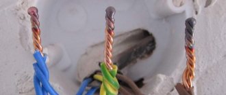
To a correctly connected residual current device, the wires from the distribution panel come to the upper terminals, and to the protected devices they leave from the lower ones.
In order for the device to decide that a leak has occurred, you need to touch the lower terminal with one control probe, from which the phase leaves the RCD, and with the other probe touch the upper zero terminal (to which zero comes from the distribution panel). In this case, by analogy with a battery test, the current will flow through only one winding and the RCD must decide that a leak is occurring and open the contacts. If this does not happen, then the device is faulty.
Characteristics of the protective device
You can find many different models of residual current switches on sale. They differ from each other in production standards, installation method and area of use.
The wrong choice of protection device can lead to the following troubles:
- The device will constantly operate in response to the slightest leaks that are present in the electrical network of each home.
- If a device with overrated characteristics was selected during purchase, it may not respond to an emergency situation. As a result, there is a high risk of electrical injury.
To avoid such incidents, it is imperative to study the characteristics of the RCD. You can read them by special markings on the body of the device.
Rated load current
This is one of the most important characteristics. The number indicates the maximum current value that can pass through the device for a long time without causing any harm to it. The magnitude is determined by the immunity of power contacts and conductors of a certain load. However, they remain in working order.
The rated current value is always indicated on the front panel of the protective device. It’s easy to find the optimal value for yourself by knowing the maximum power consumption. It must be divided by the phase voltage. It makes no sense to install an RCD with a current greater than the rated current of the machine in front of it.
Rated current values are typical for all models: 16 A, 25 A, 40 A, 63 A, 80 A, 100 A, 125 A.
What is trip current?
We can say that this is the most important parameter. It indicates the leakage current at which the protection is triggered and the device is turned off. On the body this value is indicated by the symbols IΔn. Standard residual current rating settings range from 6 mA to 500 mA.
Each of the values indicates exactly where the device can be used. For example, a device with IΔn equal to 500 mA will not be able to protect a person from electrical injury.
Non-breaking rated residual current
This is a parameter characterizing the response threshold of the device. It is designated as IΔn0. The value is always equal to half of the rated differential current (IΔn), that is, a device with a value of 10 mA will be switched off during a current leak of 5 mA.
If a leakage current less than this indicator flows through the protective device, the device will not operate.
RCD response time
This value shows the reaction speed of the protective device in an emergency situation. The nominal tripping time of the RCD is indicated by the symbols Tn. The norm is a maximum of 0.3 seconds. High-quality modern protection devices operate in 0.1 seconds, but such a high speed is not in demand.
Types of devices: AC - the device is triggered when an alternating current occurs instantly; A – with alternating or pulsating current; B – at constant, rectified and alternating; S – a certain time is maintained before triggering (0.15-0.5 sec); G – exposure time is less than the previous one (0.06-0.08 sec).
Checking the leakage current at which the RCD is triggered
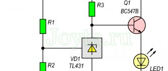
Here the same control lamp with a resistor is used, but in addition an ammeter and another variable resistance are connected to them in the circuit. The latter is often used as a dimmer - a light switch with brightness adjustment.
The verification procedure is as follows:
- The rheostat (dimmer) is set to maximum resistance and the entire circuit is connected as when checking a residual current device in a network without grounding - one probe to the phase output “from the RCD”, and the other to the zero input “to the RCD”.
- Next, slowly reducing the resistance of the rheostat, you need to observe the readings of the Ammeter - at what current strength the operation will occur, this is what the RCD is designed for.
If the RCD setting is about 30 mA, there is nothing to worry about if the operation occurs at a lower current strength - 10-25 mA - this is a kind of reserve in case of a sharp increase in the leakage current, so that the residual current device has time to be guaranteed to operate and a person, even in extreme cases, does not “get » more than 30 mA.
You can clearly see the methods of checking RCDs in the following video: