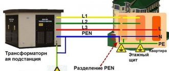
Electrical networks are complex systems. Connection diagrams for generators and transformers involve connecting a solidly grounded and insulated netal. Our power system mainly uses a system with a solidly grounded netral. However, there is equipment that must operate in conditions where a three-wire network with an isolated neutral is used.
These are mobile installations, equipment for peat mining, for the extraction of potash fertilizers and coal mines, that is, equipment operating at a voltage of 380-660 V and 3-35 kV. The power supply cable for mobile units is a four-wire cable. The difference between one type of grounding and another is that the common point of the secondary winding of the transformer is connected directly to the grounding electrode in the transformer substation.
Such a system with an isolated neutral is obtained by connecting the secondary windings of the transformer with a triangle. In this case, there is simply no middle point. This is used when safety conditions do not allow emergency de-energization due to a short circuit to ground. Such systems are designated IT.
IT grounding system or isolated neutral grounding system.
Typically this system is described something like this:
The classic system, the main feature of which is the isolated neutral of the source - “I”, as well as the presence of a protective grounding circuit on the consumer side - “T”. Voltage from the source to the consumer is transmitted through the minimum possible number of wires, and all conductive parts of the consumer equipment housings must be reliably connected to the grounding electrode. There is no zero functional conductor N in the source-consumer section in the IT system architecture.
This is where the entire description of the IT system is usually limited and it is not at all clear how to practically use it all? How to connect consumers, how to connect automation systems?
First of all, it is not clear - if the linear voltage is 380 V and the phase voltage is 220, then how will a single-phase load work? After all, there is no zero, that is, it is actually torn off. What happens when the zero breaks? That's right, everything will go to pieces - it will either burn out or simply not want to work. How do we get out of this dissonance in the IT system? Let's listen to Vasily further.
I will try to answer these questions.
First, where can one meet this system?
It is widely used on ships and anything that is considered a ship, on offshore oil and gas platforms, for example. It doesn’t matter that the platform is at the bottom of the sea, from the point of view of the maritime register it is a ship 
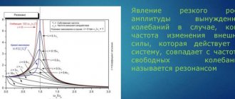
Flaws
This is considered an emergency mode and does not involve long-term operation of the equipment. This mode has the following disadvantages:
- Finding a faulty area is quite difficult;
- The insulation of electrical appliances must be designed to withstand breakdown from line voltage;
- With a prolonged short circuit, the likelihood of electric shock to service personnel increases;
- Due to the constant exposure to arc overvoltages and the constant accumulation of defects, the service life of the insulation is reduced;
- Due to the occurrence of arc overvoltages, insulation damage occurs in different places;
- A single-phase ground fault in networks with an isolated neutral makes the operation of relay protection difficult;
- Possible occurrence of a small current arc at the site of a single-phase ground fault.
A large number of disadvantages significantly reduces the use of such a scheme in networks up to 1,000 V. Such a system has become more widespread in high-voltage networks.
How to connect a single-phase load in a system with an isolated neutral?
There are two options here:
1) Oil ships often have two parallel three-phase lines, a 0.4 kV 3 phase line and a 230 V 3 phase line. To connect a device intended for use in a 230V network, you need to connect it to a 230V network BETWEEN TWO PHASES, i.e. to line voltage.
That is, use not a “star” circuit, as is usually done to obtain 220V, but a “triangle” circuit, connecting a 220 V load (which for some reason does not dare to be called “single-phase”) to one of the sides of the “triangle”.
2) Use a transformer, for example a step-down transformer 3Ph 400V / 3Ph 230V. There are also two options with a transformer, after it there can also be an IT system, or the transformer can provide an artificial neutral on the secondary winding.
Typically a 380/220 V transformer is used, the primary winding of which is connected to any two phases. If grounding is needed, then one of the terminals of the secondary winding is “solidly” grounded, and a TN-S (or, rather, TN-CS) system is obtained. With the right choice of circuit breaker and RCD, the system will provide excellent protection against short circuits and direct contact.
However, a system in which none of the transformer terminals is connected to the housing will be safer. The transformer can be anything, the main thing is that its output has a voltage of 220 V - it doesn’t matter whether it’s linear or phase.
There are usually no problems with connecting electric motors, valves and the like, but there may be problems with automation. They are due to the fact that not all devices operate correctly when their power is turned on to a linear voltage of 230 V (between phases). If you encounter this problem, you can get out of the situation either by replacing the device, or by using a low-power transformer with an artificial zero after the secondary winding.
Theoretically, yes, the device does not care where the 220V voltage comes from. But in practice, for example, instead of measuring a 4-20 mA signal, they begin to show some kind of heresy, despite the fact that the sensors are obviously working. You turn it on to ordinary phase voltage - everything works. Apparently, something is wrong with the architecture of specific devices. It doesn't happen often, but I've come across it a couple of times.
What it is
The definition of “isolated neutral” is given in Chapter 1.7. PUE, in paragraph 1.7.6. and GOST R 12.1.009-2009. Where it is said that the neutral of a transformer or generator is called isolated when it is not connected to a grounding device at all, or when it is connected through protection, measurement, and alarm devices.
The neutral is the point at which the windings of transformers or generators are connected when switched on in a star configuration.
There is a misconception among electricians that the abbreviated name for an insulated neutral is an IT system, according to the classification of clause 1.7.3. Which is not entirely true. The same paragraph states that the designations TN-C/CS/S, TT and IT are accepted for networks and electrical installations with voltages up to 1 kV.
In the same chapter 1.7 of the PUE there is paragraph 1.7.2. where it is said that with regard to electrical safety measures, electrical installations are divided into 4 types - isolated or solidly grounded up to 1 kV and above 1 kV.
Thus, there are some differences in the safety and application of such a network in different voltage classes, and calling a 10 kV line with an isolated neutral “IT system” is at least incorrect. Although schematically it’s almost the same.
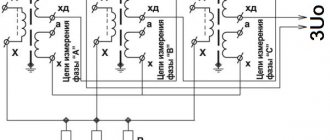
Example IT diagram
For an example of a practical circuit, see the fragment of the DC rectifier cabinet wiring diagram. Please note that the power is supplied from a 3-phase 230 V network, each of the three rectifiers is connected between phases, in line voltage.
An example of constructing a circuit with an IT grounding system
In fact, there is a protective grounding wire, it comes from the supply generator, but it only serves to ground the power supply housings.
In this case, the output voltage is constant 12 V, but can be anything! And the “minus” of all power supplies is grounded. The outputs of each power supply are supplied to the loads through circuit breakers (not shown).
I hope it has become clearer how connecting consumers to the IT system practically works. Thank you for your attention.
Voting for this and other articles will be open in about a month, follow the news in the VK SamElectric.ru group! If anyone hasn’t subscribed, I recommend it, there’s still a lot of interesting things waiting for us!
Vasily Vasilievich, author of an article about the IT grounding system
Description of the isolated device
Such a protection device is a system where the neutral wire of the generator or transformer is not connected to the ground electrode. Connection to solid grounding is allowed through signaling, protection and measuring equipment, which have high resistance.
In this case, the isolated neutral is a three-phase network connected from the electrical equipment to ground through resistors.
In this case, a system with capacitors is connected in parallel. This neutral connection diagram has two components:
- active;
- reactive.
The active circuit is designed to prevent leakage current using resistors, which, due to their high resistance, reduce its value to a minimum. The reactive system has capacitors in which one plate is connected to the line, and the second to ground.
Online electrical magazine
Electronic networks can operate with grounded or isolated neutral of transformers and generators. 6, 10 and 35 kV networks operate with an isolated transformer neutral. 660, 380 and 220 V networks can operate with either an isolated or grounded neutral. The most common are four-wire networks 380/220, which, in accordance with the requirements of the electrical installation rules (PUE), are required to have a grounded neutral.
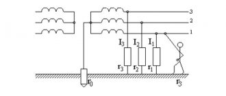
Let's look at networks with an isolated neutral. Figure 1, a shows a diagram of such a three-phase current network. The winding is shown connected in a star, but everything said below also applies to the case of connecting the secondary winding in a triangle.
Rice. 1. Diagram of a three-phase current network with an isolated neutral (a). Ground fault in a network with an isolated neutral (b).
It seems that no matter how good the insulation of current-carrying parts of the network from the ground is in general, the conductors of the network always have a connection to the ground. This connection is of a dual kind.
1. The insulation of live parts has a certain resistance (or conductivity) with respect to ground, usually expressed in megohms. This means that a current of some magnitude passes through the insulation of the conductors and the ground. With good insulation, this current is very small.
Let us assume, for example, that the voltage between the conductor of one phase of the network and the ground is 220 V, and the insulation resistance of this wire measured with a megger is 0.5 MOhm. This means that the current to ground 220 of this phase is 220 / (0.5 x 1000000) = 0.00044 A or 0.44 mA. This current is called leakage current.
Conventionally, for clarity, in the diagram, the insulation resistance of 3 phases r1, r2, r3 are depicted as resistances, each connected to one point of the wire. In fact, leakage currents in a working network are distributed moderately along the entire length of the wires, in each section of the network they are closed through the ground and their sum (geometric, i.e., taking into account the phase shift) is zero.
2. A connection of the second kind appears by the capacitance of the network conductors in relation to the ground. How to realize this?
Each network conductor and ground can be thought of as two plates of an extended capacitor. In overhead lines, the conductor and ground are like the plates of a capacitor, and the air between them is a dielectric. In cable lines, the capacitor plates are the cable core and the iron shell connected to the ground, and the dielectric is the insulation.
With alternating voltage, a change in the charges of the capacitors causes the appearance and passage of alternating currents through the capacitors. These so-called capacitive currents in a working network are moderately distributed along the length of the wires and in each individual section are also shorted through the ground. In Fig. 1, and the resistances of the capacitors of the 3 phases to the ground x1, x2, x3 are conventionally shown connected each to one point of the network. The longer the network, the larger the leakage currents and capacitive currents.
Let's see what will happen in the network shown in Figure 1a if a ground fault occurs in one of the phases (for example, A), i.e. the wire of this phase will be connected to the ground through a relatively small resistance. Such a case is shown in Figure 1, b. Since the resistance between the phase A wire and the ground is not sufficient, the leakage and capacitance resistances to the ground of this phase are shunted by the ground fault resistance. Now, under the influence of the linear voltage of the UB network, leakage currents and capacitive currents of 2 serviceable phases will pass through the fault and the ground. The current paths are shown by arrows in the figure.
The short circuit shown in Figure 1,b is called a single-phase earth fault, and the resulting emergency current is called a single-phase fault current.
Let us now imagine that a single-phase short circuit due to insulation damage has occurred not specifically to the ground, but to the housing of some electrical receiver - an electric motor, an electronic device, or to an iron structure along which electronic wires are laid (Fig. 2). Such a short circuit is called a short circuit to the body. If, in all this, the body of the electrical receiver or the structure is not connected to the ground, then they receive the network phase potential or close to it.
Rice. 2. Short circuit to the body in a network with an isolated neutral
Touching the body is equivalent to touching the phase. A closed circuit appears through the human body, its shoes, floor, ground, leakage resistances and capacitances of healthy phases (for simplicity, capacitances are not shown in Fig. 2).
The current in this circuit depends on its resistance and can seriously injure or be fatal to a person.
Rice. 3. Human contact with a conductor in a network with an isolated neutral in the presence of a ground fault in the network
From what has been said, it follows that for current to pass through the ground, a closed circuit must be present (from time to time they imagine that the current “goes into the ground” - this is a mistake). In networks with an isolated neutral voltage up to 1000 V, leakage currents and capacitive currents are usually small. They depend on the insulation condition and the length of the network. Even in an extensive network they are within the range of several amperes and below. Therefore, these currents are usually insufficient to melt fuse links or trip circuit breakers.
At voltages above 1000 V, capacitive currents are of primary importance; they can reach several 10 amperes (if their compensation is not provided). But in these networks, disconnecting damaged sections during single-phase faults is usually not used, so as not to create interruptions in the power supply.
Thus, in a network with an isolated neutral, in the presence of a single-phase fault (as indicated by insulation monitoring devices), electrical receivers continue to operate. This may be because during single-phase faults the linear (phase-to-phase) voltage does not change and all electrical receivers receive energy uninterruptedly. But with any single-phase fault in a network with an isolated neutral, the voltages of the undamaged phases in relation to the ground increase to linear, and this contributes to the appearance of a second fault to ground in another phase. The resulting double ground fault creates a severe danger for people. As follows, no matter what network with a single-phase fault present in it should be considered as being in an emergency state, because the general safety conditions in such a state of the network deteriorate sharply.
Thus, the presence of “ground” increases the risk of electric shock when touching live parts. This can be seen, for example, from Figure 3, which shows the passage of the damage current when accidentally touching the live wire of phase A and the unresolved “ground” in phase C. In this case, a person is under the influence of line voltage of the network. Therefore, single-phase faults to ground or to the body must be eliminated as soon as possible.