A cable line is a line for transmitting electricity, consisting of one or more parallel cables with connecting, locking and end couplings (terminals) and fasteners.
The main structural elements of power cables are current-carrying conductors, conductor insulation, a sheath to protect the insulation from moisture and other environmental influences, armor made of steel tapes or wires to protect the insulated sheath from mechanical damage, and an anti-corrosion coating or a special protective coating. Cable lines are laid in earthen trenches, in underground cable structures (tunnels, channels, cable shafts, collectors) directly on building surfaces or on special cable structures, on trays and cables, in pipes, openly on overpasses, etc.
Installation of cable lines, like other electricity sewerage devices, consists of two stages: preparing routes for laying cables and laying cables along prepared routes. Installation is regulated by a number of technological rules and requirements, the observance of which ensures the preservation of the level of electrical and mechanical strength of the cable that was achieved at the factory during its manufacture.
When storing and transporting cables, it is necessary to preserve the lining of wooden cable drums before laying the cable, sealing the ends of the cable; Protect cables with plastic insulation (during storage) from exposure to direct sunlight. Loading, unloading, transportation of drums and unrolling of cables is carried out using mechanisms: TKB conveyors, trucks equipped with a winch, pipe layers, forklifts and other lifting mechanisms and rigging equipment. Dropping cable drums from all types of vehicles is unacceptable. It is also not allowed to lay drums flat to avoid displacement of cable layers and turns. Under the weight of the cable, the lower turns can easily be crushed and damaged.
Laying power cable lines
This type of work involves laying a power cable with the subsequent delivery of electricity from the power source to the consumer. Several types of cable laying are regulated:
- in the ground;
- in the sewer;
- according to established structures.
Laying cable lines consists of several rather labor-intensive steps. First of all, this is the development of the project, followed by preparation of the route, installation or excavation work, installation of the structure, laying of pipes, installation of auxiliary equipment, testing by certified laboratories and connection to the cable.
Our company provides all types of work from the development of design estimates to the installation and connection of internal and external networks of various voltages. Our specialists have extensive experience in carrying out work on laying power cables with subsequent commissioning activities at facilities of any complexity, while guaranteeing high-quality performance of work within the time limits specified in the contract. We have all types of permits and SRO certificates with permits for work with a high degree of impact on the safety of capital construction projects.
Installation of cable terminations and couplings.
The most difficult job when ducting electricity with cables is installing cable terminations and connections. In recent years, new methods of terminating and connecting cables have been developed and implemented, which have significantly increased the reliability of cable networks. Instead of the previously used end seals in steel funnels and with the help of keeper tape, seals with polyvinyl chloride tape, complete rubber gloves and epoxy are now used. These cable terminations are small in size, have the necessary dielectric and mechanical strength, resistance to mineral oils, moisture and heat resistance, less labor intensity and a number of other advantages.
The general requirement for all types of terminations and connections is to ensure the tightness of the cable insulation at the point where the current-carrying conductors exit to prevent moisture from penetrating into the cable.
The reliability of couplings and seals depends on careful installation, compliance with the technology specified in the installation instructions, and sanitary hygiene standards. The entry of moisture or dirt into the coupling or seal sharply worsens the electrical strength and leads to failure of the cable when tested after installation or during operation. Therefore, work on the installation of couplings and seals must be carried out with clean hands and tools, without interruption in work until they are completely completed. Before starting work, the clutch housing must also be thoroughly cleaned on both sides and wiped with rags soaked in gasoline. The application and technology of installation of couplings and seals are discussed in the “Technical documentation for couplings for power cables with paper and plastic insulation up to 35 kV”, therefore only general information and individual elements of installation of couplings and seals are given below.
Installation of terminations and couplings begins with installation operations called cutting the end of the cable, which consists of sequentially removing protective covers, armor, sheath and insulation of the cable over a certain length. The result is a stepped cutting, the size of the steps depends on the voltage, type and dimensions of couplings and terminations.
First, before cutting, check the paper insulation for the absence of moisture: tear off the paper strips from the end of the cable and dip them into paraffin heated to 140-150 ° C. When the insulation is wet, cracking and foaming are observed. The moistened insulation in an area of 250-300 mm is removed and checked again until positive results are obtained.
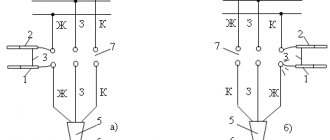
When cutting the end of the cable, a bandage (Fig. 2, a) made of two or three turns of galvanized steel wire is placed over the jute cover; unwind the cable yarn (Fig. 2, b) to the bandage and leave it to protect the armor from corrosion after installing the coupling (temporarily wrap it around the uncut part of the cable); apply a second bandage at a distance of 50-70 mm from the first (with connecting couplings of 100 mm); use the area between the two bands to connect the grounding conductor; cut the armor (Fig. 2, c) along the edge of the bandage and remove (Fig. 2, d) together with the pillow (Fig. 2, e); remove sulphate paper and bitumen composition (previously carefully heat it with a quick fire with a gas burner or blowtorch); wipe the lead or aluminum sheath with a rag soaked in gasoline or transformer oil heated to 40 °C in the area for soldering the grounding conductor and sealing the coupling neck; make two annular cuts in the lead or aluminum shell (Fig. 2, f) at a distance of 20 mm from each other and at a distance determined from the armor cut according to the technical documentation (with an aluminum shell, make a spiral cut, Fig. 101, j), make two longitudinal cuts shells (Fig. 2, g) at a distance of 10 mm from one another; remove a strip of the sheath (Fig. 2, h), and then the entire sheath (Fig. 2, i) from the end of the cable to the second cut (the sheath between both annular cuts is temporarily left to protect the belt insulation when bending the cores); bend the cores according to a template or manually with a bending radius of at least ten times the height of the sector or the diameter of the core along the insulation; bandage the core insulation at the cut point with two or three turns of cotton thread and remove the paper tapes, unwinding and removing them from the bandage; bend the lead sheath by flanging; After connecting or terminating the cores, the previously left annular shell belt is removed.
Rice. 2. Cutting a cable with paper insulation: a - applying a bandage over the jute cover on the cable, b - unwinding the outer jute cover, c - cutting the armor with an armor cutter, d - removing the armor, e - removing the cable yarn (cushion), f - making a ring cut sheath, g - making longitudinal cuts to the sheath, h - removing a strip of lead sheath, i - removing the entire sheath from the part of the cable to be cut, j - spiral cut of the aluminum sheath using an NKA knife with a cutting disk
Cable cutting with plastic insulation is carried out in the same sequence as with paper, stepwise removal of the hose, armor, cushions underneath, screens and insulation. Removed insulation is restored by insulating the joints and terminations with paper rolls and rollers, and more recently with self-adhesive tapes.
The connection of cables for voltages up to 1000 V is carried out, as a rule, in cast iron couplings, in which the main insulation is casting mastic, which is quite sufficient for low voltage while maintaining the insulating distances between the cores with porcelain spacers. The coupling housing SCh (SChm) consists of two halves connected by bolts. In the lower coupling half, there is a groove along the entire perimeter with a sealing gasket made of oil-resistant rubber or tarred hemp rope placed in it; in the upper coupling half, along the entire perimeter of the junction, there is a protrusion that fits into the groove of the lower coupling half. A resin tape is wound onto the cables at the points where they enter the coupling, which is crimped into the protrusions located in the neck of the coupling body.
Porcelain spacers are installed on the cores, one on each side of the connection point (closed PM - when connecting the cores by soldering and open P - when crimping or welding). In SChM couplings, instead of spacers, insulating windings are used on exposed areas of the cores. The spacers are fastened to the cores with cotton tape boiled in cable composition. The main insulation is a bitumen composition, poured in a heated form (up to 50-60 ° C) through holes in the upper half of the body in three or four stages to avoid the formation of shrinkage cavities and voids.
After the composition has cooled to ambient temperature, a gasket made of rubber or hemp rope is placed in the groove of the filling hole, the cover is secured with bolts and the joint seams, necks, couplings and bolts are covered with hot bitumen composition or varnish. The couplings are grounded with a copper stranded wire, which is connected at one end to the shells and armor tapes of each cable, and at the other (with a pressed or welded tip) to the contact pad (under the grounding bolt) in the lower half of the coupling. The connection of cables in a cast iron coupling is shown in Fig. 3, a, b. The connection of the cores in the coupling must ensure reliable contact, have low transition resistance and mechanical strength. The connection point must be free of sagging, burrs and other protruding parts, with a flat surface and smooth rounded transitions.
Rice. 3. Cast iron couplings: a - normal version MF, b - small-sized MF; 1,8 - upper and lower coupling halves, 2, 10 - windings made of resin and paper tapes, 3 - bandage, 4 - porcelain spacer, 5 - cover, 6 - tightening bolt, 7 - grounding conductor, 9 - connecting sleeve, 11 - plug, 12 — clamp
Connecting cables for voltages up to 1000 V is also carried out using epoxy couplings SE, PSSL, etc., which are produced in the form of ready-made kits having removable or non-removable rigid forms made of plastic or metal, filled in with an epoxy compound at the installation site.
The PSSL coupling made of self-adhesive tapes is designed for connecting cables with plastic insulation laid in the ground and cable structures. When cutting the ends, the plastic insulation of the cores is restored with self-adhesive tapes, and the plastic hose is restored with a heat-shrinkable tube using KO-916 varnish. The mounted coupling is placed in a protective plastic or metal casing.
To terminate cables for voltages up to 1000 V with paper insulation, it is recommended to terminate the internal installation with sealing of the cores with tubes of different designs: TV (heat-shrinkable), K (silicon-organic), N (made of nayrite rubber), T (three-layer plastic), as well as wearing rubber gloves and steel funnels. Recently, new seals have appeared based on self-adhesive KVsl tapes and in heat-shrinkable KVTp gloves.
End seal KVsl (Fig. 4) is intended for terminating paper-insulated cables for voltages of 1-6-10 kV with aluminum and copper conductors with a cross-section of up to 240 mm2 in dry rooms with a level difference of up to 10 m and is performed with self-adhesive tapes LETSAR (or LETSAR- LPt) and varnish KO-916, which have good adhesion to cable materials and high electrical characteristics. A variety of KVsl terminations are the end seals of the internal KVslt installation made of self-adhesive tapes and polyethylene heat-shrinkable tubes for paper-insulated cables for a voltage of 1000 V.
Rice. 4. Sealing of KVsl: 1 - layer of varnish KO-916, 2 - sealing winding with LETSAR tape, 3 - winding of cores with PVC tape, 4 - insulating winding of cores with LETSAR tape, 5 - bandage winding with LETSAR tape, 6, 7 - central and side sealing cone inserts
Termination in heat-shrinkable polyethylene gloves is used for terminating three-core (ZKVTp) and four-core (4KVTp) power cables with paper insulation up to 1000 V and consists of a heat-shrinkable polyethylene glove, to the fingers of which heat-shrinkable polyethylene tubes are glued to seal the cores. The tubes are sealed on the cylindrical part of the tip with heat-shrinkable polyethylene cuffs, and sealed in the lower part of the glove at the tips on the metal sheath of the cable with a special hot melt adhesive (GIPC-14-17), while the diameter of the tubes for cables with a cross-section of 16-240 mm2 is from 14/7 to 30/15 (the numerator indicates the internal diameter before shrinkage, the denominator indicates the internal diameter after shrinkage in a free state). The shrinkage of the tubes is carried out evenly by heating (gas burner flame) starting from the root of the embedment. After shrinking, the tubes should fit tightly around the cable cores (without wrinkles or folds).
The end seal in KVR rubber gloves has the same purpose as the KVTp seal, and consists of a rubber glove with nairite rubber tubes glued to the fingers to seal the conductors. The tubes capture the cylindrical part of the tips and are sealed on them with bands made of steel strips. The lower part of the glove is glued to the cable sheath and sealed with a clamp.
KVET seals with three-layer tubes consisting of a middle polyethylene, inner and outer polyvinyl chloride layers are installed in the same way as seals with nayrite tubes. At the lower end of the tube, only a polyethylene layer is left, which is processed with a file and coated with PED-B glue. Part of the outer polyvinyl chloride layer is also treated and lubricated with glue, which is then filled with epoxy compound. Seals with heat-shrinkable polyvinyl chloride tubes have the same purpose and application as seals with other tubes. The tubes, put on the tips, are seated with the flame of a gas burner, starting from their middle, first up and then down. After cooling, the tubes are sealed with LETSAR tape and coated with KO-916 varnish. The gap between the cut of the core insulation and the tubular part of the tip is filled by winding with LETSAR-L GTm tape (instead of the previously used winding of cotton tape with each layer coated with an epoxy compound). KVE epoxy terminations with Nairite rubber tubes on the cores are designed for terminating three-core power cables with impregnated paper insulation for voltages up to 10 kV. The plastic housing and coupling cover ensure guaranteed dimensions between the cable cores at the outlet, as well as between the cable cores and the housing. The new design increases the reliability of the couplings and their ease of installation.
When making end seals in KVB steel funnels (rarely used), the funnel is put on the cable below the point where the conductors are routed (the root of the termination), sealed with several layers of insulating tape and filled with heated cable mastic. For winding, sticky polyvinyl chloride or polyethylene varnished fabric tape LKhM-105 is used with gluing with tsapon-glyphthalic varnish. Seals are carried out in oval (KVBo), round (KVBk) and oval small-sized (KVBm) funnels.
Seals in steel funnels are labor-intensive and not reliable enough in operation. If there is a difference in cable laying levels, the cable impregnating composition may leak out from the bottom seal. At high temperatures and ambient humidity, the seals absorb moisture, and at low temperatures, cracks appear in the bitumen mastic, through which moisture from the environment can penetrate into the cable. Other couplings and seals are used, given in the technical documentation, most of which are produced by manufacturers complete with parts and installation materials.
Issues covered
- What methods exist for laying cables across enterprises and production premises?
- Why are end seals and couplings installed on cables and what types of coupling designs exist for 1 kV cables?
18936
Bookmarks
Comment 1
Comments 1
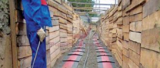
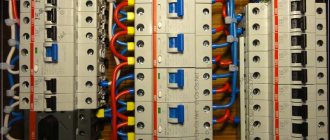
Cable laying in trays
Indoors, cables are laid along wall surfaces in boxes, cables, pipes and trays. From the point of view of installation and maintenance, the most convenient option is to lay the cable in electrical trays. This gives quick access to the cable for maintenance and repair work.
Electric trays produced today have an acceptable aesthetic appearance. To select the correct tray, take into account the cable cross-section and its weight. The tray is installed on special shelves on racks, secured with studs to the walls and ceiling. Our company’s specialists will select the best option for laying cables in trays, in accordance with the customer’s wishes and at the best prices.
Pipe transfers
The single-phase design of the cable with XLPE insulation imposes certain restrictions on the methods of their installation, in contrast to cables of traditional three-phase designs with impregnated paper insulation. For example, in [3, 4, 8] the permissible temperature conditions for cable operation are specified for various methods of laying it, and in [7] the features of laying cables with XLPE insulation are emphasized in places that require their mechanical protection using pipes: when crossing engineering structures , natural obstacles, etc. In a number of projects on certain sections of the cable route (often under roads and railway embankments), phase-by-phase laying of cables in metal pipes is assumed, which is prohibited in the instructions of all manufacturers. With this installation, an additional heat source is Foucault currents flowing through a metal pipe. Heating of the pipe itself causes additional heating of the cable enclosed in the pipe, thereby reducing its throughput.
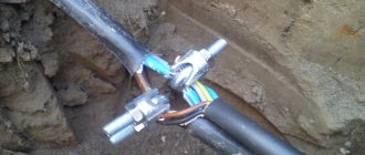
Pipe transfers must be made either with asbestos-cement pipes or HDPE pipes, the pipe joints must be connected hermetically. The joints of AC pipes must be concreted, and the joints of HDPE pipes must be welded. Pipe transfers made by AC pipes must be checked for transmission. Before pulling the cable, the pipes must be cleaned and, if necessary, washed with water under pressure. When tightening a traction cable into a pipe, it is necessary to stretch a piston-caliber through it, the diameter of which is 5 mm less than the inner diameter of the pipe. For pipe transfers up to 10 m long, the pipe diameter must be at least 1.5 cable diameters, for pipes longer than 10 m - at least 2 cable diameters.
To reduce friction of the cable in the pipe, it is necessary to use a lubricant. Technical Vaseline or soap solution can be used as a lubricant (Fig. 6). Pipe transfers should be made straight, turns should be smooth (no more than 3°), since at large angles the traction cable may jam. Turns with large angles must be made open with a length of at least 3 m, with the possibility of installing corner rollers. The use of corrugated pipes is unacceptable, since due to their low mechanical strength, when pulling the cable, the walls of the pipes are cut through and when a “stocking” gripper passes through the cut pipe, it is destroyed.
Laying cables in the ground
For external cable laying, a cable of the appropriate cross-section is selected based on the expected loads and power consumption of electricity. In a project for the power supply of a structure, a special section describes in detail the steps for laying the power cable.
Laying a power cable is a separate type of work with clearly defined regulations for each stage. The depth of the trench must be more than 70 cm. When laying several cables in one trench, a distance of 10 cm must be provided between them. If it is technologically necessary to lay the cable in a shallower trench, special protection is developed to prevent mechanical damage.
The route design is developed based on the shortest distance between connection objects, taking into account the best conditions for cable safety. When developing a route, designers take into account environmental conditions and the presence of other technical networks. It must be taken into account that in one trench there cannot be more than six cables with a voltage of up to 10 kW, and no more than two cables with a voltage of up to 35 kW.
Work on laying the power cable must be carried out by organizations that have the appropriate approvals and permits. Our company's employees have all the necessary permits.
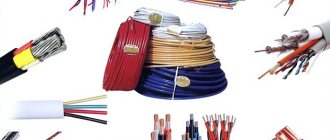
Technical characteristics of power cables
In accordance with GOST, cables are produced for power and control purposes. Cable power lines are designed to transmit and distribute electricity in electrical installations. Control - used to organize control circuits, signal transmission, remote control and automation. Electric transmission lines (power lines) from 6 to 10 kV and more are carried out with power cables.
Inside the SC there may be 1, 2, 3 or 4 insulated conductors, hermetically sealed with a protective film (Fig. 1).
Fig. 1 three-core SC “AAB”: 1 – segment cores; 2,3,4 – insulating material; 5-hermetic shell; 6,7,8 – final protective cover.
Current-carrying conductors are of aluminum and copper origin; in the construction of SCs, aluminum material is usually used. The cores can be stranded or single-wire (when marking, the value “cold” is added).
Insulation. When making a cable, the cores are insulated; it can be made of special rubber, paper or plastic material. For power structures, insulation made of plastic material and paper impregnated with a special composition is most often used.
For cables with voltages up to 10 kV, each core is insulated separately (paper insulation). Then belt insulation is carried out - all the cores are insulated together from the sheath. The gaps between the cores are filled with paper strands.
The mentioned insulation technique makes the cable smaller in diameter and gives it the required electrical strength.
Protective shell. Used as a sealing material, preventing damage to the cable structure in the event of exposure to external factors.
The shell can be done:
- often made of aluminum;
- lead (for cable power lines in water);
- rubber (polychloroprene rubber);
- plastic (polyvinyl chloride material).
Protective layer. Performs its functions relative to the cable sheath. Serves as a barrier from external influences, protects the internal structure from mechanical damage and corrosion. Depending on the purpose of the cable, its protective cover may consist of a cushion, armor and outer cover.
Armored structures are used in the creation of cable power lines used for laying in water and land. Their protective layer, on the outside, is provided with an additional layer that protects against chemical influences.
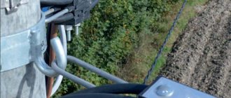
Laying power cables in tunnels
In the presence of unfavorable geodetic or natural conditions, power cables are laid in pipes and tunnels. The same work is carried out when laying the cable if it is expected to intersect with other communications or in aggressive soils.
Modern technologies make it possible to carry out horizontal directional drilling, which makes it possible to lay cables without opening the ground.
Testing the sheath of cables with XLPE insulation
The cable sheath after laying in the ground must be tested with a constant voltage of 10 kV applied between the metal screen and the ground electrode for 5 minutes. In order to timely detect possible damage, it is recommended to test the shells immediately after laying the construction lengths in the areas between the wells (couplings) before backfilling the trench. After laying the construction length of the cable, it is necessary to remove tools and equipment from the trench and sprinkle the cable with a sand-gravel mixture no less than 100 mm thick.
During the test, care should be taken to ensure that no one present at the test or bystanders can touch the cable sheath along the entire length of the test section.
If the cable sheath does not pass the tests, it is necessary to identify and open for inspection the place of damage (MP) and repair the sheath. MF can be determined using induction and acoustic methods or the overhead frame method.
Repairs to the cable sheath must be carried out by trained personnel. To repair the shell, it is recommended to use heat-shrinkable cuffs wrapped with sealing materials (Fig. 7).
After repairs, it is necessary to fill the cable with a sand-gravel mixture with a thickness of at least 100 mm and retest the cable sheath.
If, during testing of sheaths, the ends of the cables, closed with caps, were opened, then after testing, new caps must be immediately installed at these ends.
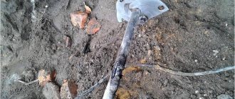
To avoid damage to the main insulation of the cable cores, burning the damaged area of the cable sheath is strictly prohibited (Fig. 8).
After complete installation of the cable, terminations and couplings, it is necessary to retest the cable sheath.
Cable line design
When designing cable lines, it is necessary to take into account the features of the network, the characteristics of the relief, the results of geodetic studies, the conditions for their further use and much more. Designers must receive a clear technical specification containing the wishes of the customer and the requirements for the project of land owners. As a result, the Customer receives a package of documents, which includes: a single-line diagram of the electrical network, diagrams of the intersection of the line with engineering systems, a route plan on the required scale, an explanatory note from the designers, and a situational plan.
We prepare design and estimate documentation and the entire range of works, allowing the customer to significantly reduce the cost of providing electricity to their facility. The costs of laying power cables are based on project cost calculations. The calculation also includes the collection and generation of permits for all types of work, excavation work, the cost of the cable, the cost of geodetic work and construction of the cable line. Next, all work related to laying, protecting and covering cable networks from possible accidental damage is taken into account. It is important to carefully consider the calculations for landscaping the surrounding area and restoring the removed coatings during the work.
By contacting our specialists, you can not only competently carry out all stages of work on laying cable lines in Moscow, but also save a lot of money on obtaining permits, conducting laboratory tests, etc.
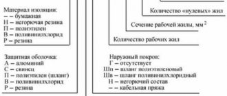
Labeling rules
The marking of power cables consists of symbols indicating the material used for manufacturing: cores, insulation, sheath and protective layer. The name is very important when choosing cables for laying overhead and cable power lines.
The use of copper conductors has no symbolism, aluminum – at the beginning of the name, o.
Paper insulation also does not have designations; all other insulating materials:
- P – polyethylene;
- B – polyvinyl chloride;
- R – rubber insulation.
The following symbol corresponds to the material from which the protective sheath is made:
- A – aluminum;
- B – polyvinyl chloride;
- C – lead;
- P – polyethylene;
- R – rubber.
The marking ends with letters indicating the type of protective layer:
- G – there is no armor or external barrier coating;
- (D) – corrugated aluminum layer;
- T – reinforced lead layer;
- Seam - a smooth aluminum layer in a polyvinyl chloride hose.
The letter “B” at the end of the marking is a cable with depleted impregnation. Cable power lines with depleted impregnated insulation and lead sheath are laid on routes with a height difference of up to 100 m. Restrictions are eliminated when using an aluminum sheath in the design.
The letter “C” indicates the use of paper insulation impregnated with a non-draining mass made on the basis of ceresin. This type of cable is used for organizing cable power lines on steeply inclined routes. No restrictions on elevation changes. After the letter marking there are numbers indicating the cross-section of the conductive wires.
Cold shrink couplings.
These couplings have all the advantages of heat-shrinkable couplings. In addition, the installation of a cold shrink sleeve does not require a heating operation, which makes it possible to reduce the installation time of such a sleeve by approximately half compared to the installation time of a heat-shrinkable sleeve.
The cold shrink sleeve consists of EPDM rubber, pre-tensioned onto a spiral that is removed during installation. When removing the spiral cord using the free ends of the cord specially left on both sides of the coupling, the coupling easily shrinks, ensuring complete sealing of the cable.
The thick walls of the coupling provide additional protection from mechanical stress. In addition, EPDM rubber is resistant to moisture, acids, alkalis and ultraviolet radiation.
A cold shrink coupling for a single-core cable is shown in Fig. 12.
Rice. 12. Cold shrink coupling : 1 - extruded two-layer silicone body; 2 - semiconducting plate; 3 — general protective casing made of EPDM rubber; 4 — mastic for leveling the electric field; 5 — sealing mastic; 6 - copper mesh and screen connector; 7 - connecting sleeve
The basic installation operations of such a coupling are shown in Fig. 13.
Rice. 13. Installation of a cold shrinkage coupling : a - preparation of screens for connected cables; b - connection of cores by crimping; c - placing a plate with a semiconducting layer at the point of contact connection of the cores to level the electric field; d - closing the junction of the cable cores with a coupling; d - pulling out the spiral cord from both sides of the coupling; e - coupling ready to apply voltage to the cable
Heat-shrinkable sleeves and cold shrink sleeves retain the flexibility of the cable and do not collapse under cyclic temperature loads and soil displacements when the seasons change. The longitudinal breaking force of the coupling is 60% of the cable breaking force.
The locking properties of such couplings make it possible to increase the permissible difference in cable route levels for cables with impregnated paper insulation.
Trench requirements
According to PUE-7, the trench lies at different depths (the distance between the cable and the surface). Key points:
- depth of at least 70-80 cm (taking into account the sand cushion);
- from 1 m under the square, street (1 m 10 cm with a pillow);
- up to 0.5 m (with a cushion of 60 cm) when water enters a building with a maximum section length of 5 m.
Depth parameters must be strictly observed. Proper installation will protect the cable line from overheating in summer. Stable ground temperature ensures a high current load on the core. At the desired depth, the pressure is distributed evenly, which prevents squeezing of the conductor. The deep location of communications protects people from electric shock during excavations.
Heat-shrinkable sleeves.
These couplings are used for any method of laying cables, are reliable in operation (service life of at least 30 years), and are characterized by ease of installation (approximately 1 hour for termination and approximately 2 hours for connecting cables with voltage of 6-10 kV).
Voltage can be supplied to the cable line immediately after installation of the coupling.
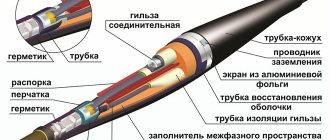
Rice. 7. General view of the cut single-core XLPE cable : 1- current-carrying core; 2 — screen made of semi-conductive plastic; 3 — XLPE insulation; 4 — screen made of semiconducting plastic; 5 - water-swelling layer; 6 - screen made of copper wires; 7 — outer protective plastic shell; 8-wire bandage
A wide range of heat shrinkage allows you to use one coupling size for different types of cables and core sections, which significantly reduces the stock of couplings. For example, only two standard sizes cover the entire range of cable cross-sections used in distribution networks with a voltage of 6-10 kV (one standard size is used for cross-sections of 70-120 mm, the second for cross-sections of 150-240 mm). The reinforcement of heat-shrinkable couplings is practically not subject to aging and can be stored indefinitely.
The principle of heat shrinkage is based on the technology of manufacturing cross-linked polymers with plastic shape memory. The heat-shrinkable sleeve kit includes elements (tubes, cuffs, gloves, hoses, etc.) supplied in an extended state, which makes it easy to put them on the elements of the cut cable. When heated with a propane-butane torch or a hair dryer, these parts shrink and tightly envelop the cable elements, thereby creating a sealed and mechanically strong structure. The shrinkage temperature is 120-150°C and is not dangerous for cable insulation.
Reliable sealing is ensured by special adhesive and mastic sealants applied to the internal surfaces of the coupling elements. Simultaneously with the heating of the heat-shrinkable elements, the sealing materials melt and spread, filling all the voids.
Due to special additives (ZnO), sealing materials have semiconducting properties and, therefore, equalize the electric field. Due to this, the cause of discharges in areas of increased electric field strength (in the contact connections of the conductors, at the cut of the screen) is completely eliminated.
The basic installation operations of a heat-shrinkable end sleeve for a single-core cable are shown in Fig. 8.
The installation of a heat-shrinkable end sleeve of a three-core cable is not fundamentally different from the installation of a single-phase cable sleeve. Three-core cable couplings use heat-shrinkable gloves that are placed over the three phase cores of the stripped cable.
Rice. 8. Installation of a heat-shrinkable end sleeve : a - stripped cable with a tip; b - shrinking the regulator tube, leveling the electric field; c - shrinkage of the vein cuff; g - installation of the grounding conductor and seating of the hose; d - shrinkage of the end cuff; e — seating of the waist cuff.
The heat-shrinkable end sleeve of a three-core cable is shown in Fig. 9; heat-shrinkable sleeve for connecting three-core cables - in fig. 10.
Rice. 9. End heat-shrinkable sleeve : 1 - tip; 2- end cuff; 3 — vein tube and finger cuff; 4 - glove; 5 — tape regulator for leveling the electric field; 6 — waist cuff; 7 - grounding conductor
The basic installation operations of a heat-shrinkable sleeve for connecting three-core cables are shown in Fig. eleven.
Rice. 10. Heat-shrinkable coupling : 1 - protective housing; 2 - bolted contact connection of cores; 3 - cuff insulating the contact connection; 4 - glove; 5 - phase tube; 6 — cuff for sealing the coupling body; 7 - conductor ensuring continuity of the grounding circuit.
Rice. 11. Installation of a heat-shrinkable coupling : a - shrinkage of the vein tubes; b - winding the tape-regulator; c - shrinkage of gloves; d - connecting the cores with bolted connectors and wrapping them with regulator plates; d - shrinkage of lining cuffs; e - shrinkage of insulating cuffs; g - hose shrinkage; h - securing the grounding conductor and winding with screen tape; and - winding sealant tape; j - shrinkage of the protective casing
The grounding conductor of the end couplings and the conductor ensuring the continuity of the grounding circuit in the couplings are mounted using a solderless grounding system supplied with the coupling kit. The contact connection of the grounding conductor with the metal sheath (screen) of the cable is covered with sealing tape, which protects this connection from corrosion.
The grounding conductors of the couplings are made of flexible copper wire. The cross-sections of these conductors must be no less than:
16 mm - for cable cross-sections up to 120 mm;
25 mm - for cable cross-sections up to 240 mm.
When installing heat-shrinkable couplings, it is possible to avoid such environmentally harmful operations as soldering during the installation of lead couplings and bitumen filling of couplings. There are no environmentally hazardous gas emissions during heat shrinking.