Electric cable marking.
The main principle of organizing electrical wiring and laying lines is the competent choice of cables and wires used. At this stage, the operating conditions of the product are taken into account, based on which a decision is made on the required cross-section, number of cores, type of sheath, insulation and other important parameters. Key data about the cable is encoded in its markings - a unique set of letters and numbers that is printed on the outside of the product or indicated on a special tag. The correct selection of products depends on how accurately the abbreviations and other designations are deciphered. Errors made at this stage can cause the cable to overheat during direct operation, and will also lead to a short circuit and even a fire.
Designation of wires in electrics by letter
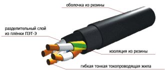
Electrical communications in the domestic and industrial spheres are organized through insulated cables, inside of which there are conductive cores. They differ from each other in insulation color and markings. The designation l and n in electrical engineering makes it possible to speed up the implementation of installation and repair activities by an order of magnitude.
The application of this marking is regulated by a special GOST R 50462 : this applies to those electrical installations that use voltages up to 1000 V.
As a rule, they are equipped with a solidly grounded neutral. Often residential, administrative and business facilities have electrical equipment of this type. When installing electrical networks in buildings of this type, it is necessary to have a good understanding of color and letter instructions.
Power cable marking.
The choice of suitable wires and cables is largely determined by the specific installation conditions. For example, for those products that will be installed outdoors, it is better to give preference to a rubber shell, and for indoor work, a PVC shell and insulation is suitable. To simplify the selection of the optimal product, Russian GOST 18690-2012 obliges manufacturers to apply a symbol to their products. Cable marking allows you to quickly determine the following significant parameters:
- number of cores;
- section;
- the material from which the structural elements are made.
The electrical cable can be single or multi-core. Copper is most often used as a conductor, but in some cases aluminum is also used. It is cheaper, but is inferior in conductive capacity by no more than 20%, which is easily compensated by an increase in cross-sectional area. The last parameter allows you to determine the level of internal resistance.
If you plan to lay a power cable in a group or it will be used in public buildings, you should pay special attention to insulation and sheath materials, which should have low levels of gas and smoke emission. Equally important is the presence of an aluminum screen. Information about all these parameters can be obtained from the labeling, the decoding of which should be entrusted to a specialist if you do not have your own experience working with similar products.
Requirements for wiring colors during installation
A copper wire with one or two cores is pulled from the distribution box to the switch. The number of cores depends on the number of keys on the device. The phase should be broken, not the zero. During operation, it is allowed to use a white conductor for power supply, making a mark on the diagram.
The socket is connected taking into account the polarity. The working zero will be on the left, the phase will be on the right side. Grounding is located in the middle of the device and is clamped with a terminal.
If you have two cables of the same color, you can find the phase and neutral using a tester, an indicator screwdriver, or a multimeter.
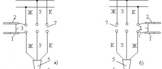
On the electrical diagram it is worth indicating what L and N mean, but there are several of them used in electrical engineering. The single-line display shows the power part - type of power supply, number of phases per consumer. Here it is advisable to draw one notch on a single-phase network, three on a three-phase network and indicate the wires in color. Switching and protective equipment is marked with special symbols.
Correct marking and color marking of wires ensures the quality of installation and maintenance of the line. Labeling in accordance with international requirements allows electricians and home craftsmen to navigate the circuit.
Power cable marking system.
The letters and numbers indicated on the product will help you quickly understand what type of product is in front of you. To decipher, it is necessary to take into account not only the symbolic designations of certain characteristics, but also their position. According to accepted standards, power cable marking is based on the principle indicated in the table below.
| Location | Encoding | Characteristic |
| 1st position | Letter | Core material |
| 2nd position | Letter | Insulation material |
| 3rd position | Letter | Type of containment (if available) |
| 4th position | Letter | Armor type (if available) |
| 5th position | Letter | Characteristics of outer cover, cable structure |
| 6th position | Digital | Number of conductors |
| 7th position | Digital | Core cross-sectional area |
| 8th position | Alphanumeric | Climatic conditions for operation |
| 9th position | Alphanumeric | Indication of GOST or TU |
In order to quickly find the right brand when viewing a cable catalog, it is important to remember not only the decoding of the alphanumeric designations, but also the type of characteristics reflected on each individual position.
SPECIFICATIONS
- Type of climatic modification – B, placement categories 2-5 according to GOST 15150.
- Temperature range during operation: from -50 °C to 70 °C,
- The cables are resistant to high relative air humidity up to 98% at ambient temperatures up to 35 °C.
- Installation of cables without preheating at a temperature not lower than -15 °C.
- Permissible bending radius, mm, not less than:
- for unarmored cables: 6 outer diameters;
- for armored cables: 14 outer diameters.
- Construction length: - selected from the range of 50, 100, 200 meters depending on the nomenclature.
- Fire resistance of cables with the index “FR”………………………………………………………..not less than 180 minutes.
- Smoke formation during combustion and smoldering of cables does not lead to a decrease in light transmittance for cables: - with the indices “ng(A)-LS”, “ng(A)-FRLS”………………………………………… ..more than 50%; — with the indices “ng(A)-HF”, “ng(A)-FRHF” …………………………………………………….more than 40%.
Cable catalog.
Depending on the design features of the conductive product, its symbol may not contain all parameters. So for an aluminum electrical cable, the marking begins with the letter A. If it is not in the first position, this means that this is a product with conductive copper cores. The following letters indicate what the insulation is made of. This term refers to the protective covering of conductors, which is necessary to prevent them from shorting with each other. The insulation material is designated by the abbreviations V, P, Pv, Ps, R, NR, F, C, K, KG. The following letters will tell you the type of inner containment used. It is laid on insulated cores and provides higher cable resistance to water, mechanical damage, and extreme temperatures. The internal protective shell is designated by the letters A, C, P, Pu, B or P, but is not present in all products. Therefore, if there is a blank in the 3rd position, this means that this structural element is not included in the product. An equally optional element is armor, the type of which is indicated on the 4th position of the marking with the abbreviations BS, BbG, Bb, Bl, Bn, K, D, P. The armor is made of steel tapes or wire braiding and is needed to increase the mechanical strength of those wires and cables that bear increased load. Most often, protection is provided by a simple outer shell. It is made of dielectrics: fluoroplastic, polyethylene, PVC or rubber. The specific material is indicated by the letters V, Shv, Shp, Shps, N on the 5th position of the power cable marking. The letters O, E, G may also appear here, which indicate the design features of the product.
If we consider the digital markings that occupy the 6th and 7th positions, then they are always present. In some cases, numbers may be included to indicate the level of permissible operating voltage. If this is not the case, it means that the cable is designed for a 220 V network. Climatic zones of operation may not be indicated (they are used only on special-purpose products) and the number of GOSTs and TUs used.
Phase designation (L)
The AC network includes live wires. Their correct name is “phase”. This word has English roots, and is translated as “line” or “active wire”. Phase conductors pose a particular danger to human health and property. For safe operation they are covered with reliable insulation.
The use of exposed live wires is fraught with the following consequences:
- 1. Electric shock to people. This can result in burns, injuries and even death.
- 2. The occurrence of fires.
- 3. Damage to equipment.
When designating wires in electrics, phase conductors are marked with the letter “L”. This is an abbreviation of the English term “Line”, or “line” (another name for phase wires).
There are other versions of the origin of this marking. Some experts believe that the prototype was the words “Lead” (lead wire) and Live (indication of voltage). Similar markings are also used to indicate the clamps and terminals to which the linear wires must be connected. For example, in three-phase networks, each line is also marked with a corresponding number (L1, L2 and L3).
Current domestic standards governing the designation of phase and zero in electrical engineering (GOST R 50462-2009) require linear conductors to be placed in brown or black insulation. Although in practice, phase wires can be white, pink, gray, etc. In this case, it all depends on the manufacturer and the insulating material.
Alphanumeric marking of power cables.
Having figured out the sequence in which cable characteristics are marked, you can begin to directly decipher them. Currently, there are more than 300 product brands that have their own coded designation. The table below will help you understand the most common lettering instructions that are used to describe product properties.
| Abbreviation | Possible position in marking | Decoding |
| A | 1, 3 | Aluminum |
| AA | 1 | Aluminum core and aluminum sheath |
| AC | 1 | Aluminum conductors and lead sheath |
| IN | 2, 3, 5 | Vinyl (PVC) |
| P | 2 | Polyethylene |
| Ps | 2 | Self-extinguishing polyethylene |
| Pv | 2 | Vulcanized (cross-linked) polyethylene |
| R | 2, 3 | Rubber |
| HP | 2 | Non-flammable rubber |
| F | 2 | Fluoroplastic |
| C | 2 | Film insulation |
| TO | 2 | Cable purpose: control |
| Kg | 2 | Flexible cable |
| WITH | 3 | Lead |
| P | 3 | Polyethylene hose |
| Pu | 3 | Reinforced polyethylene hose |
| B | 4 | Armor made of galvanized steel strips |
| BS | 4 | Lead armor |
| BbG | 4 | Armor made of steel profiled tape |
| BB | 4 | Two steel bands |
| Bl | 4 | Two steel belts with a plastic belt cushion |
| Bn | 4 | Steel tapes with non-flammable winding |
| TO | 4 | Steel wire armor with steel tape protection |
| D | 4 | Braided from two steel wires |
| P | 4 | Flat steel wire armor |
| G | 5 | The design provides protection against corrosion |
| E | 5 | Aluminum foil screen |
| ABOUT | 5 | Insulated conductors are connected by a winding |
| IN | 5 (if the last letter in the marking) | Paper outer insulation |
| Shv | 5 | Vinyl hose |
| Shp | 5 | Polyethylene hose |
| Shps | 5 | Self-extinguishing polyethylene hose |
| N or NG | 5 | Non-flammable composition |
| G | 5 | No protective layer |
| HF | 5 | Low gas emission |
| L.S. | 5 | Low smoke emission |
| ng-LS | 5 | Does not support combustion, low smoke emission |
| FR | 5 | The cable has increased fire resistance |
| FRLS | 5 | Cable with increased fire resistance and low smoke emission |
The first number after the letters indicates the number of conductive wires. After the “X” sign, their cross-sectional area is indicated. If neutral conductors are provided in the cable design, then after the number and cross-section of the main conductors a “+” sign is placed with a further indication of the number of conductors of smaller cross-section and their exact area.
PE conductor - what is it and what is it for?
The TN-C grounding system, despite the fact that it is still used in most apartment buildings, is outdated and is being actively replaced by TN-S or TN-CS, which are more advanced in terms of protection. As a result, in electrical circuit diagrams N is used as the working zero, and the PE conductor is the protective zero that appears in the circuit after the PEN wire is separated, or taken directly from the ground loop.
Electrical wire marking.
The power wire is most often single-core, but even if there are 2-3 phases, they do not have insulation in their design, like a cable. Conductors have only an internal protective sheath. The special letter P (wire) or the abbreviation PP (flat wire), PN (heating wire) after the first A (aluminum conductors) will indicate that you are looking at just such a product. However, the marking of the first P may also apply to polyethylene insulation of cable conductors. However, in this case, the symbol will have a noticeably large number of letters and numbers.
Electrical wire markings are based on the same principle as cables. The only difference is that the last position may indicate the purpose: G - flexible, C - connecting, T - for installation in pipes.
Home electrical wire marking
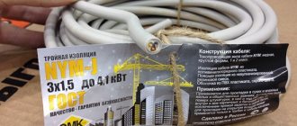
The Electrician's Bible PUE (Electrical Installation Rules) states: electrical wiring along its entire length should make it possible to easily recognize the insulation by its color.
In a home electrical network, as a rule, a three-wire conductor is laid, each wire has a unique color.
- Working zero (N) is blue, sometimes red.
- The neutral protective conductor (PE) is yellow-green.
- Phase (L) – can be white, black, brown.
In some European countries there are constant standards for the colors of wires by phase. Power for sockets - brown, for lighting - red.
An example of decoding cable markings.
To make it easier to understand the accepted conventions, consider several standard options.
- ANRBG 3X16 + 1X10. Cable with 3 aluminum cores (A), the cross-section of which without insulation is 16 square meters. mm (3X16). The design provides a neutral conductor with a cross-section of 10 square meters. mm (1X10). The insulation is made of non-flammable rubber (NR). The letter B in the abbreviation indicates the presence of armor made of steel tape, and the letter G indicates the absence of an external protective cover.
- AVVGng 3X2.5. The numbers in the cable marking indicate that it contains 3 cores with a cross-sectional area of 2.5 square meters. mm excluding insulation. Their base is aluminum (A). The second and third letters indicate that PVC (vinyl) was used for both conductor insulation and internal protective sheathing. Bare cable (G) does not support combustion (ng).
- VVGEng-LS 10X0.5. The basis of this cable is 10 copper cores (no A at the beginning) with a cross-sectional area of 0.5 square meters. mm (10X0.5). The conductors are insulated with PVC, which also formed the basis of the internal protective sheath (two V at the beginning of the marking). The presence of the letters G and E indicates that the cable is shielded, but does not have an external protective sheath. The addition of ng-LS indicates that combustion is not maintained and little smoke is emitted.
Why separate the PEN conductor if a jumper is placed between the PE and N buses - the “physics” of the process
A direct answer to this question is not given in the PUE and GOSTs - there are only recommendations “how to do it”, and “why” is not considered, most likely based on the assumption that it should be clear anyway. Therefore, all subsequent explanations should be taken as the opinion of the author, supported by the principles of connecting electrical wiring and the requirements of the PUE.
The main points here are:
- In any diagram that illustrates the division of a PEN conductor into PE and N, grounding is always placed first and a jumper goes from it to the working zero. This is the main requirement that must be taken into account when dividing a PEN conductor - on the contrary, this is never done under any circumstances.
- Even separately made grounding is most effective when connected through an RCD. Otherwise, even if the voltage from the body of the electrical device goes into the ground, there is still a risk of electric shock to a person, although much less.
- Any wire has some electrical resistance; accordingly, the longer the wire, the higher its resistance to electric current.
To understand the “physics of the process” itself, it is necessary to consider how various connection schemes behave when an emergency situation occurs.
If there is no jumper and RCD circuit breaker, zero and ground are not connected
The phase enters the body of the device, from it goes to the grounding bus, from it goes into the ground along which it goes to the transformer substation.
If we take the average value of the resistance of the grounding device to be 20 Ohms, the short circuit current will not be large enough to turn off the input circuit breaker. Accordingly, the electrical circuit will work until the damaged area burns out (in any case, there will be an increased temperature in this place and the wire will sooner or later deteriorate), or the damage develops into a full short circuit between phase and zero.
In the best case scenario, a person may be noticeably “tickled” by an electric shock or the device may be damaged. At worst, the device may ignite and cause a fire.
If there is a jumper between zero and ground, there is no RCD
In this case, the circuit works approximately the same as if you simply put a PEN conductor into the house, with the only difference that the person will be more protected due to grounding. This will happen precisely because of the length of the wire - since in any case the ASU is located at some distance from the apartment or house, the resistance of the wire must be taken into account.
When a phase is shorted to the body of the device, the leakage current will go to the grounding bus, where it will have only two outputs: part of it will go into the ground, and the other will return along the neutral wire, causing the incoming apartment circuit breaker to turn off.
That is, in this case, the jumper is needed in order for the protective circuit breaker to operate.
If there are jumpers between PE and N, an RCD is installed
Since the neutral and ground wires have a certain resistance to electric current, it is clear that in this case the RCD will operate normally. If a short circuit occurs to the device body, the leakage current, first of all, goes through the wire to the RCD itself, and then goes to the ASU of the residential building. Here, again, it partially goes into the ground and partially comes back through the jumper, provoking the switching off of the input circuit breaker, but most likely it won’t come to this, since the RCD will trip earlier.
It is clear that in this case the jumper does not play a special role and is more of an extra reinsurance in that almost incredible case if the RCD circuit breaker does not work.
If there is no jumper between PE and N, an RCD is installed
Such a circuit will work in exactly the same way as if there was a jumper between the ground and the working zero. The only exception to this is the lack of insurance in case the RCD suddenly fails. Then the circuit will work according to the first option - the input circuit breaker may not work until the short circuit to the device body turns into a short circuit between phase and zero.
In fact, this scenario is practically impossible, because in fact such a connection is already a TN-S or even TT grounding circuit, which provides two-factor protection - without it, such a connection will not be accepted by energy supervision.
Table for decoding letter markings of power cables.
In some cases, marking power cables (deciphering which for an untrained person seems like a real nightmare) can become a significant difficulty in tasks related to cable and wire products. In fact, deciphering the cable markings is not that difficult. The detailed meaning of each letter symbol of the cable brands is given in the cable catalog tab and the table below:
| Ordinal location - position of parts of the marking | Scope of product (cable) characteristics described by this part | Explanation of possible meanings of this part of the marking |
| 1st capital Latin letter (foreign markings only) | Compliance with standard | N - the cable is manufactured according to the German VDE standard; Li - stranded copper conductors made in accordance with VDE (for control cables it is placed at the end of the marking); H - harmonized wire (HAR approval); The absence of a letter means that the cable does not comply with foreign standards, or the standard is not indicated in the marking. |
| 1st group of numbers (foreign markings only) | Rated voltage | 05 - Rated voltage 300/500 V; 07 - Rated voltage 450/750 V; Often missing from labeling . |
| 1st capital letter | Conductor material | A - current-carrying conductor made of aluminum; AC - current-carrying conductor made of aluminum with a lead sheath; AA - the same, aluminum shell; No letter or space (underscore) - conductive conductor made of copper . |
| 2nd capital Latin letter (foreign markings only) | Insulation type | Y - Polyvinyl chloride (PVC) insulation; YH - Halogen-free polyvinyl chloride insulation; Y(ST) - insulation and sheath made of PVC plastic; This part of the marking is almost always present . |
| 2nd capital letter | Scope of application of the cable (wire, cord) | B - aviation (on-board aircraft) wires; K - control cable (not used for power cables); KP/KE - submersible cable; KN - oil submersible heating cable; G - cables for the mining industry (“mining” cable); M - installation wires and cables; P - wire; O - optical (not used for power cables); U - installation cable; Ш - cord; ШБ - household cord; E - for special mine conditions; KPS - twisted pair cable for alarm systems; Foreign markings: J - Cable for alarm systems; M - installation wires and cables; SL - Control cable; KG - flexible cable (in fact, it is not an independent designation and is a combination of the designation “K - cable” indicating the degree of flexibility (G - flexible); The absence of a letter means that this cable or wire is power . |
| 3rd capital letter | Degree of flexibility | K - flexible core for stationary installation (foreign markings only); G - “flexible”, as a rule, means that the structure is based on a stranded core; The letter G is missing - the cable is not intended for installation in moving structures or routes with complex geometry. In most cases, the conductor in such cables is a single-wire core. |
| 4th capital letter | Core insulation material | B - polyvinyl chloride (PVC); P - polyethylene; C - glass insulation; A - asbestos insulation; R - rubber; NR - non-flammable rubber; F - fluoroplastic; C - film insulation (for installation wires); For winding wires: EV - high-strength enamel; EL - varnish-resistant enamel; ET - heat-resistant enamel; B - cotton yarn; K - nylon; Ш - natural silk; ShK - artificial silk nylon; O - one layer of insulation (maybe the 4th letter); Absence of a letter - uninsulated conductors . |
| 5th capital letter | Availability of screen | E - general screen; C - presence of a copper screen (foreign markings only); Y - presence of a screen made of aluminum foil (foreign markings only); Absence of a letter means unshielded cable . |
| 6th capital letter | Sheath material for cable products, armored cover | RG - presence of armor (foreign markings only); B - armored cover (armor) made of steel tapes; BBG - armored cover made of steel profiled tape; Bn - armor made of steel strips, with a protective cover that does not support combustion; B - PVC; D - double wire; K - armor made of round galvanized steel wires, enclosed in a protective cover; SB - lead armor; Absence of a letter - cable without armor or without armor and outer sheath . |
| 7th capital letter | Type of protective cover. Purpose of the outer layer, designation of the core structure | V - PVC insulation (foreign markings only); B - PVC; -B - paper insulation (at the end of the designation); G - anti-corrosion protective layer; Absence of the letter G - protection from mechanical damage; O - insulated conductors are combined into a common sheath, braid (for wires); Png - shell made of a polymer composition; Shv - protective layer (or shell) - pressed PVC hose; Shp - the same, but made of cross-linked polyethylene; Absence of a letter - cable without additional outer layers . |
| Lower case | Additional performance characteristics. Lowercase letters are placed next to uppercase letters, without spaces. In some cases they may appear after the 7th capital letter. | c - vulcanized (polyethylene); d - water blocking tapes (used to seal a metal screen); h - filling between the cores; ng() - a shell made of non-combustible material. The flame retardation class (capital letter) is indicated in parentheses. If there is no value in brackets, then the cable has flame retardation class A; b - without a pillow; l - the pillow contains lavsan tape; 2l - the pillow contains a double lavsan ribbon; c - self-extinguishing; E - shielded; T - the wire is intended for installation in pipes; Absence of a letter - no additional design characteristics . |
| 8th capital letter | Operational characteristics: design features, climatic design, etc. | U - paper insulation with increased heat resistance; -P - flat design (as practice shows, this designation can be located anywhere on the marking, and is also often indicated by the lowercase letter “p”. For example: “VVGPng-LS”, “VVGpng-LS”, “VVGngp-LS”, and "VVGng-LS-P."); FR - fire-resistant cable; HF - halogen-free cable; LS - cable with reduced smoke and gas emissions; LTx - reduced level of toxicity of combustion products; Climatic version: -HL - cold resistance; T - increased resistance to thermal effects; Absence of a letter means no special performance characteristics . |
| Lowercase letters in brackets (can be indicated without brackets at the end of the marking, after the numbers) | Core type | cooler - single-core design; mn - multi-core design (for more details, see the article “Abbreviations for designating the type of conductor of cable and wire products when marking cables: ozh, mn, ok, os, ms”); Absence of a letter - the type of execution is not specified . |
| 1st digit (in some cases 3rd) | Rated voltage | 1 - rated cable voltage (example), kV; No number - low voltage cable up to 660 V. |
| 2nd digit (usually the 1st, always comes before the multiplication symbol - “X” or “*”) | Number of cores | 1- 4 - power cables; 2-14 - installation cables; 4-37 - control cables |
| 3rd digit (usually the 2nd, always follows the multiplication symbol - “X” or “*”) | Core cross-section, mm² | 0.75-10 — control cables 0.35 — 0.75 — installation cables |
| A group of digits separated by a multiplication symbol immediately following the "+" sign | The presence of neutral conductors with a cross-section different from the cross-section of the current-carrying conductors. | For example: +1X120. The cross-section of the neutral conductor according to the PUE is 50% of the cross-section of the main current-carrying conductor, provided that the cross-section of the supply conductor is more than 25 mm2; Absence of designation - the neutral conductor is missing, or the cross-section coincides with the current-carrying ones . |
| Capital or lowercase Latin letters at the end of the marking | The presence of a neutral conductor and a grounding conductor with the same cross-section as the current-carrying conductors. | N – the cable contains a neutral core; N, PE - the cable contains a neutral conductor and a grounding conductor; (for more details, see the article “Abbreviations for designating the type of conductor of cable and wire products when marking cables: ozh, mn, ok, os, ms”); Lack of designation - the neutral conductor and the grounding conductor are either absent in the cable design, or not indicated in the marking, or the neutral conductor has a different cross-section from the current-carrying conductors . |
Grounding symbol (PE)
In addition to the designation of phase and zero, electricians also use a special letter indication PE (Protective Earthing) for the ground wire. As a rule, they are always included in the cable, along with the neutral and phase conductors. Contacts and clamps intended for switching with the grounding neutral wire are also marked in a similar way.
For ease of installation, the grounding conductors are placed in yellow-green insulation. The DIYer should understand that these colors always indicate the ground wires only. Yellow and green are never used to indicate phase and zero in electrical engineering.
As practice shows, when organizing electrical networks in residential buildings, violations of generally accepted standards for the use of insulation color and corresponding alphanumeric markings are sometimes allowed. In this case, it is not always enough to have the ability to decipher the designations L, N or PE.
In order for the connection of electrical equipment to be truly safe, it is necessary to check whether the markings correspond to the actual state of things. To do this, use special devices (testers) or improvised devices. If you have no experience in such work, for your own safety it is better to invite an experienced electrician with the appropriate permit.
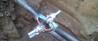
Designation l and n in electrics
The designation of phase and zero in electrics was introduced to ensure that electrical networks are safe and easy to use. For this purpose, special letter markings (l and n) and insulation of the corresponding color are used. There may also be conductors marked PE in yellow-green color: this is how grounding wires are designated.
In addition, the same letter designations are used on connecting contacts and terminals. All that needs to be done when installing an electrical appliance is to connect each of the wires to the terminal. To be on the safe side, it is advisable to check each of the wires with a tester.
The photo below is a good example of how L and N are designated in electrical equipment. In particular, the photo shows the UZM (multifunctional protection device) terminals for correct connection of the wires.
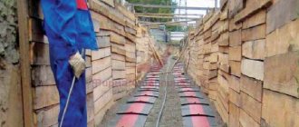
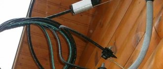
Marking of cable lines.
Wires and cables laid in boxes and on trays must be marked at the beginning and end of the trays and boxes, as well as at the points where they are connected to electrical equipment, and the cables, in addition, also at route turns and branches. Each cable line must be marked and have its own number or name. Labels must be installed on exposed cables and cable joints. Tags must be secured to the cables with nylon thread or galvanized steel wire with a diameter of 1 - 2 mm, or plastic tape with a button. The place where the tag is attached to the cable with wire and the wire itself in damp rooms, outside buildings and in the ground must be covered with bitumen to protect it from moisture. On hidden cables in trenches, tags are installed at the end points and at each coupling. Tags should be used: in dry rooms - made of plastic, steel or aluminum; in damp rooms, outside buildings and in the ground - made of plastic. Designations on tags for underground cables and cables laid in rooms with a chemically active environment should be made by stamping, punching or burning. For cables laid in other conditions, markings may be applied with indelible paint. On cables laid in cable structures, tags must be installed at least every 50 - 70 m, as well as in places where the direction of the route changes, on both sides of passages through interfloor ceilings, walls and partitions, in places where cables enter (exit) into trenches and cable structures. On hidden cables in pipes or blocks, tags should be installed at the end points at the end couplings, in the wells and chambers of the block sewer system, as well as at each connecting coupling.
DESIGNATION
- In cables with bare copper conductors, the index “M” is added after the sheath designation (Ш) (for example, МКЭШМ 2х0.75).
- In cables with a common screen made of tinned copper wires, after the designation of the screen (E) of the cable, the index “l” is added (for example, MKElShVng(A)-ls 4x2x1.0).
- In cables with a common screen made of aluminum foil film, the index “f” is added to the designation of the screen (E) of the cable (for example, MKEfKShVng(A)-ls 4x2x1.0).
- Cables sheathed in PVC plastic with reduced flammability can be manufactured in a cold-resistant design, and the index “ХЛ” is added to the designation of the cable brand.
- Cables sheathed from a halogen-free polymer composition can be made from materials resistant to sunlight, with the “UV” index added to the cable brand designation.
TRANSPORTATION AND STORAGE
- Transportation and storage of cables must comply with the requirements of GOST 18690-2012 and GOST 31996-2012.
- The conditions for transportation and storage of cables in terms of exposure to environmental climatic factors must comply with coolant group 3 according to GOST 15150-69.
- It is allowed to store cables on drums in sheathed form in open areas.
- The shelf life of cables in open areas is no more than two years, under a canopy - no more than five years, in enclosed spaces - no more than 10 years.