Wiring type and its parameters
At home, you most often have to deal with alternating current, much less often with direct current.
Typically, direct current is measured in batteries and batteries; house wiring always runs on alternating current. Even if the electrical network is powered by batteries (a backup power source, the main one in the absence of a centralized power supply), it must contain an “adapter” - a device that converts direct current into alternating current. When figuring out how to measure current with a multimeter, you need to clearly understand: to work with direct current, use the DCA (A-) segment of the multimeter, for measuring alternating current, use the ACA (A~) sector. The designations are associated with abbreviations of English terms: direct current amperage (DCA) and alternating current amperage (ACA) is the designation of alternating current on a multimeter.
Typically, multimeters allow you to measure microcurrents - up to 200 mA - and stronger ones (up to 10A). Devices that allow measurements in more powerful electrical networks have an additional socket for a plug (probe) marked 20A. Typically, in models with four connectors, two are designed to measure current in different ranges, one is for other measurements (voltage, resistance).
The COM (COMMON) connector, common (universal) for all types of measurements, is intended for the negative (black) probe of the multimeter.
Thus, to measure current with a multimeter, you need to connect the black probe to the COM connector, and the red probe to the socket for checking microcurrents or ordinary currents. For sockets and switches, the device regulator is set to the alternating voltage sector, for batteries and batteries - constant. If the level is unknown in advance, the highest value allowed by the device is selected.
Important: if no energy-consuming device is connected to the outlet (on the switch), the electrical circuit is open and there is no current in it!!! Measuring the current directly in the socket or on the contacts of the switch is useless and dangerous! This causes a short circuit.
How to measure voltage in an electrical outlet with a multimeter
A multimeter is a universal device that can be used to accurately determine voltage and current. The device is widely used by electricians and is also often used at home. Every novice user should know how to measure the voltage in an outlet with a multimeter.
What parameters can be measured with a multimeter
This hand-held measuring device is designed for various electrical tests.
A multimeter is a multifunctional device that can be used to determine the following technical parameters:
- voltage – constant and variable;
- resistance range;
- capacity;
- frequency;
- inductance;
- direct and alternating current strength;
- temperature regime;
- transistor gain;
- checking diodes and transistors;
- calculation of electrical resistance with transmission of a signal of reduced circuit resistance.
Many models have a knob on the front panel that helps you change values.
Some multimeters have additional equipment and can measure mass, footage or time in seconds
The measurement results are visible on the built-in monitor. On the side of the device there are two sockets for probes - red (positive potential) and black (with negative potential).
Functional elements of a multimeter
Modern manufacturers produce various models of multimeters. Digital instruments with various additional functions, which are considered more accurate, are widely popular. An error of up to those percentages is considered normal. The lower the deviation indicator, the more reliable the test check.
Even the simplest electrical measuring device is capable of determining the most standard values - current, voltage and resistance. More expensive multimeters are equipped with special sensors for measuring temperature. Also, using such a hand tool, capacitance, intervals between pulses, frequency and inductance are determined.
Among the functional capabilities of the multimeter are:
- Recognition of disturbances in the operation of an electrical circuit. The device is capable of detecting the resistance value, which has fallen below the required scale, using a sound signal - “diagnosis”.
- Checking semiconductor elements. Using a multimeter, you can check diodes, transistors or thyristors, namely their serviceability.
- Many advanced models are equipped with displays that receive a signal and can carry out the necessary calculations.
The most popular additional features are:
- recording of the detected value by the device - push-button or automatic;
- illumination of indicators on the screen;
- power failure counter;
- reboot indicator;
- automatic detection of measurement boundaries.
In professional models, the minimum accuracy error is established. Sometimes digital processing ability is used. The necessary maximum parameters are fixed in the working memory, with the help of which the device calculates the average value.
Also on the front side of the multimeter there is a “continuity” icon and a knob for switching ranges
Almost all multimeters have catchy symbols that display the functional elements of the device:
- “DCA” – direct current measurement;
- “Ω” – resistance icon;
- “ACV” – constant voltage indicator;
- “DCV” is a designation for alternating voltage.
Some electrical measuring devices have two indicators at once - digital and dial. To make it easier to work with the device, two measuring scales are used, which allow you to measure in different values.
How to measure the voltage in an outlet with a multimeter - instructions
Even a beginner can check an outlet using a multimeter. You can use either an analog device or a digital device. Measuring voltage is not difficult, based on a detailed description of step-by-step actions:
- Turn on the power supply to the 220 V outlet. To do this, you need to find a circuit breaker.
- Connect the probes to the tester. The black one goes into the socket marked “COM” or a small “-” symbol, and the red one goes into the socket marked “VΩ” or the “+” symbol.
- Press the button that turns on the multimeter. Typically, such a switch is designated “ON/OFF”.
- Turn the knob on the front panel of the device in the direction of the AC scale and fix the voltage of 220V, corresponding to the indicator in the socket. Typically, multimeters have a designation of 200V and a final 600V or 750V. Since there is more than 200V in the socket, it is recommended to set it to the maximum value of 600 or 750V.
- When turned on, the device should display a zero indicator. Fixed probes are inserted into the socket openings, and it does not matter which hole the red or black test lead is placed into.
- After the probes are set, the operating voltage value is displayed on the screen, which should not exceed the limit of 220 - 240V.
- The AC neutral line is checked further. This slot is characterized by an L-shape for all hotspot directions. The end of the red test lead is placed in the hot slot, then the black test lead is inserted into the neutral socket. A value of at least 100V and no more than 120V should appear on the multimeter. After this, the red probe is moved to another hot slot and the same readings are obtained as for the first one - 110-120V.
- The probes must be removed from the sockets and the multimeter must be turned off. Now you can connect electrical appliances to the outlet.
Why do you need to measure current?
The voltage and resistance of the electrical circuit, which are measured in units such as volts (V) and ohms, respectively, have a significant impact on the amount of current. In this case, an increase in voltage with a constant resistance of the electrical circuit causes an increase in current strength, and an increase in the resistance of the circuit with a constant voltage value leads to its decrease. Current (I), voltage (U) and resistance (R) depend on each other and are related by empirical formulas:
- I = U/R
- U = I*R
- R = U/I
In this case, it is simplified to assume that a current of 1 A appears in a conductor with a resistance of 1 Ohm if a voltage of 1 V is applied to it.
Current measurement
By measuring the CT with a multimeter, you can:
- clarify the actual power consumption of a particular electrical appliance;
- find defects in an electrical appliance if its actual power does not correspond to the value stated in the documentation;
- find out the electrical capacity of autonomous power sources (batteries, etc.);
- identify the existence of current leakage in electrical circuits and, if necessary, localize the defective area;
- check the battery charger to ensure that the charging current corresponds to the specified value, etc.
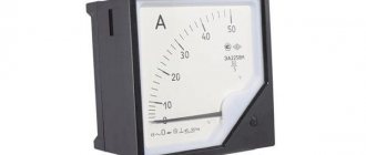
Such measurements are carried out using special instruments - ammeters. There are enough varieties of them on the domestic market to satisfy the needs of all buyers.
The most popular, especially at the household level, are small multifunctional (ammeter + ohmmeter + voltmeter) multimeters, with which you can measure almost all the necessary parameters of an electrical circuit.
Features of measurements
If you imagine that electric current is water flowing through a pipe, and voltage is the operating pressure, then many concepts and formulas become clear. When the pipe is blocked, there is pressure, but no water. Until a consumer appears, that is, a load, it will not flow. And resistance is pitfalls in the riverbed that interfere with the free passage of the stream, but force it to work.
Current strength in physical terms is the number of charged particles flowing per unit time through a certain point in the system. It is measured in amperes A or milliamps mA.
Measurements are carried out using ammeters, as well as household or professional multimeters. Digital meters are simple and easy to use. They allow you to set not only current and voltage, but also other characteristics - resistance, capacitance of capacitors, frequency of alternating current, etc. A current strength exceeding 15 mA is considered dangerous for humans, at which muscle spasm occurs. And a shock of 100 mA is almost always fatal. Therefore, all work related to live networks must be carried out strictly in compliance with safety regulations.
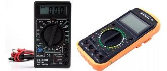
Digital multimeter
The most convenient is a multimeter, in which it is enough to simply set a specific measuring mode. There is no need to additionally specify the tolerance range, since the device itself adapts to the circuit parameters, takes measurements and produces the required result.
The image below shows the first position of the handle, which has several positions demonstrating AC and DC voltage. The first is indicated by V AC (~ symbol), the last DC (—), in the range of volts and millivolts. The current strength A is similar, not being divided into current types, but having a gradation in amperes and milliamps.
In addition, the function of measuring resistance and chain ringing is mandatory.
At the bottom there are several sockets used to activate the measurement wires. The socket marked with the second position COM is used for the main black wire. The third position shows the socket for making basic measurements using the red cord. The permissible limits for voltage and current measurements are shown below. The fourth socket, indicated by position 4 in the image, is used to measure current in amperes, with a maximum limit of no more than 10 A. All readings appear on the display with digital graphics, which is indicated by position 5.
A multitester with an indication of the measurement range is more common, primarily because it costs much less.
When using a multimeter, it is necessary to indicate both the operating mode and the alternating and constant currents. In the same sector, a switch is installed in the required measuring range, expressed in mA, µA and A. The example shown shows 4 socket connections. Two of them are for red wires, measuring up to 200 mA and up to 10 A. Voltage, resistance, capacitance and other indicators are measured using a separate socket.
Types of Multimeters
All devices, according to their design and principle of measuring current indicators, can be divided into two types:
- Analog testers.
- Digital multimeters.
Briefly about each type of measuring device.
Analog multimeters
The main difference between analog and digital devices is the presence of a digitized scale with an arrow. They are very easy to use and quite cheap. But their disadvantage is considered to be the presence of errors in the readings. Although this can be corrected using a tuning resistor. But, all the same, it is unlikely that it will be possible to achieve accuracy comparable to digital instruments. And in some cases, this is really necessary.
Digital multimeters
Since the presence of a scale with an arrow is mentioned as one of the main differences between analog devices, it is logical to assume that they are absent in digital devices. And indeed it is. The measurement results are displayed on the display, which can be LED or liquid crystal, in the form of specific numbers.
As already mentioned, the main advantage of digital testers is the accuracy of current measurement. In addition, they are not much more difficult to use than analog ones. Even a beginner can cope with measurements after a short instruction. The downside is the higher cost of a digital device.
Measurement order
A multimeter for measuring current is connected to an open circuit. This is the main difference from the voltage measurement procedure, in which the tester is connected to the circuit in parallel. The indicator of the amount of current that passes through the device is displayed by an arrow on the scale (if we are talking about an analog device) or is displayed on the liquid crystal (LED) display.
There are different ways to break the circuit under test to connect the device to it. For example, by disconnecting one of the terminals of the radio element using a soldering iron. Sometimes you have to cut the wire with wire cutters or pliers. When determining the current value of a battery or accumulator, such a problem does not exist, since a circuit is simply assembled, one of the elements of which is a multimeter.
Types of multimeters
There are two types of testers on the modern electrical appliance market:
- Analog.
- Digital.
The main elements of analog instruments are a scale with divisions marked on it, which is used to determine the indicators of electrical quantities, and an arrow-pointer. Such multimeters are in high demand among beginners due to their low cost and ease of use.
But, along with these positive aspects, analog testers also have a number of disadvantages, the main one of which is the high measurement error. It can be somewhat reduced due to the tuning resistor, which is structurally included in the device. However, if you need to measure electrical parameters with high accuracy, it is better to use a digital device.
Basic principles of current measurement
The main condition that must be met when measuring current in an electrical circuit is to connect the tester to a wire break in this circuit, that is, to become its component during the measurement. Before measuring the current strength with a multimeter, it is equally important to correctly set the following on the device:
- measurement mode (DC or AC);
- upper measurement limit.
Incorrectly set parameters will certainly lead to breakdown of the measuring device.
When the user does not know the magnitude of the current in the circuit, it is necessary to set the maximum measurement limit. If the set range turns out to be too high, it is gradually reduced using the tester operating mode switch.
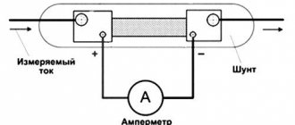
A device for measuring current is connected in an electrical circuit in series with the load. When measuring large currents, the multimeter is connected to the circuit through a current transformer, shunt or magnetic amplifier. If measurements need to be carried out in electrical circuits with a voltage of more than 1 kV, use a current transformer (alternating current) or a magnetic amplifier (direct current).
Instructions for the multimeter
On the front part we see a switch with which we can select the functions we need. Let's look at the symbols that are on the multimeter. I marked each function with a number for ease of perception.
1) Resistance Ω. This icon tells us that we are going to measure the resistance of some conductor or resistor.
2) Constant voltage =V. By setting the switch to this icon, we can measure DC voltage.
3) AC voltage ~V. With this function we can measure the value of AC voltage.
4) Measurement of the gain of hFe transistors. I don’t use it, because I have a transistormeter special for this purpose. You can read more about the gain in this article.
5) Capacitor capacity F. Everything is obvious. Capacitance can be measured.
6) DC voltage current measurement =A. We can measure the current strength of direct voltage.
7) Measurement of AC voltage current ~A. With this function we can measure the current of AC voltage. For example, this function is useful when we need to find out how much current flows in the circuit when we connect an incandescent lamp or some other load to a 220 Volt network.
8) Diode continuity test and continuity test of conductors. Shows resistance if you measure the integrity of conductors. When checking diodes, it shows the voltage drop across the PN junction. The beauty of this function is that if a resistance of less than 100 Ohms is displayed (it is different for different models), a screaming signal is heard from the multimeter. A very convenient function for checking diodes, as well as the integrity of wires and fuses. If you buy a multimeter, be sure to buy one with a diode tester, otherwise such a multimeter will suddenly lose its functionality.
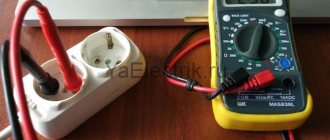
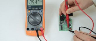
How to correctly check the current in a socket with a multimeter
You cannot insert probes into the socket to the phase and zero contacts; to perform the test, you must connect a “load,” that is, any electrical appliance.
Below is a diagram for measuring the current of a transformer; a regular incandescent lamp is connected to its contacts as a load. As can be seen from the display readings, the current is 1.14 A. It is important to understand that in the home electrical network the indicators are higher, so you should not take risks by directly “shorting” phase and zero with multimeter probes.
In fact, the following sequence of actions is performed to check:
- the current in the socket selected for measurements is turned off (automatically on the panel). You can check whether the outlet is connected or not by measuring the voltage with a multimeter. This procedure is safe even under load;
- The front (protective part) is removed from the socket so that there is direct access to the contacts. After this, a contact is connected to one of them, for example, a phase one, through a terminal block from the plug (wire) of any low-power electrical appliance - a table lamp, for example;
- further, as shown in the illustration, also through the terminal blocks, the free pin of the plug (lamp wire) to one of the probes, the free contact of the socket to the other. In most modern multimeters, the polarity of the connection (where to connect the positive probe, where the negative probe) is not important, the readings on the display will be the same. If the polarity is reversed, a “-” sign will appear next to the numbers;
- After the connections have been made, the socket will be automatically plugged back into the general house circuit. After turning the lamp switch to the “ON” position, measurements can be taken. The current will vary for different consumer devices. So, when connecting a regular incandescent lamp, the current will be about half an ampere.
Alternating current
Most networks—domestic or industrial—carry alternating current. It is much easier to transform and loses less when transmitting over long distances than a permanent one.
When measuring voltage or resistance, the multimeter is connected in parallel with the load, but to determine the strength, the tester must be built into an open circuit. Therein lies a certain difficulty. But you don't have to cut the wires. You can use detachable connectors. For example, a special pair of conductors with pins at one end and crocodile clips at the other. The pins are inserted into the socket, and the “crocodiles” close the circuit at the terminals or plug.
Homemade devices are also convenient. If you have to take a lot of measurements, you can’t do without them. In the picture you see a device that will help you work without any danger of getting an electric shock.
It is important to distribute all the conductors correctly: the phase is connected to the contact of one socket, the zero to the other, and a jumper is installed between the others. To measure current, connect the load to the first outlet and the multimeter to the second. When power is applied in a closed circuit, it is easy to determine the current strength.
Without breaking the conductor, you can take measurements using current clamps. They are designed to work with both alternating and direct current. The device looks like a multimeter with two round clamps. The wire to be tested is placed between them. The principle of setting modes and range is similar to the multitester.
How to measure current with a multimeter on a battery
Any machine has its own minimum amount of current leakage, which varies, in amperes, from 0.01 to 0.08. First, it’s worth understanding the causes of current leakage in the car. One of them may be that the owner simply forgot to turn off the lights, for example.
There are cars that have a bad factory design built into them. This can be considered a glass heating system, which conducts its power chain bypassing the ignition switch. Let’s not forget about children who love to sit in the driver’s seat, turning various instrument levers.
The second global reason may be an incorrect connection. Thus, during the period of global interest among car enthusiasts in music and radios, the battery charge was melting before our eyes. This happened because the installers did not know how to connect the devices correctly. One ignition wire passed through the ignition switch did the job. If you have an anti-theft system installed, and the next morning you find an empty battery, then there is no need to guess.
We also advise you not to leave recorders, radars and other devices in cigarette lighters and sockets. Not all cars provide them when the ignition is not working.
In order to determine current leakage, you need to perform some steps. So, with the hood open, unscrew the negative terminal from the battery. Next, after removing it, set the multimeter to amperage mode. Place a probe into the gap between the terminal and the battery contact. Numbers appear on the display that reflect the amount of leakage. If you see the readings in mA, then you can rest assured. If the measurements are presented in amperes, then hurry to take certain measures.
Leak detection
Sometimes, even after a short period of inactivity, a car battery refuses to provide the necessary charge to start the engine. In this regard, car owners are interested in how to measure the battery current with a multimeter and where the leak came from.
A battery is a source of direct current with a fairly large capacity. Electricity is produced in it as a result of chemical reactions, and after discharge, the battery can again make up for the lack of current from the charger.
There is a current leakage rate in the car system that does not exceed 30-50 mA. But even in winter this should not cause the battery to drain. During parking, electricity is spent on the operation of car gadgets - alarms, clocks, audio systems, navigation, etc. Their energy consumption is low - no more than a few tens of milliamps.
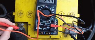
Critical leaks that lead to battery discharge occur due to additional consumers or a short circuit in the circuit. You can determine them using a multimeter:
- Turn off all devices that consume energy. Turn off the ignition and remove the key from the lock.
- Set the constant current measurement mode to 10 A.
- Create a break in the circuit - connect the negative of the battery to the COM connector of the multimeter, connect the red probe with the help of an alligator clip to the on-board network of the car.
In this state, there should be no leaks above the permissible 30-50 mA. But if they are present, you will have to look for the reason. Non-standard consumers may be among self-installed devices - radio, fog lights, heated seats, alarms, etc.
To accurately determine which of these is the “culprit” for energy losses, each type of equipment must be disconnected from the circuit and the tests repeated.
Wires located near moving parts of the car often become chafed, which can cause a short circuit. Therefore, all electrical communications are examined for damage and isolated.
If even after these measures it was not possible to eliminate the leak, the test is carried out with the fuses and relays disconnected. The reasons may also lie in a faulty generator or starter.
How to measure DC voltage with a multimeter
Let's take a battery like this. As we can see, it says a current of 550 mAh, which it can supply to the load for an hour, that is, milliamps per hour, as well as the voltage that our battery has - 1.2 Volts. Voltage is understandable, but what is “current for an hour”? Let's say our load, a light bulb, consumes a current of 550 mA. This means the light bulb will shine for one hour. Or let's take a light bulb that shines weaker, and let it consume 55 mA, which means it can work for 10 hours.
We divide the 550 mA value that is written on the battery by the value that is written on the load and get the time during which all this will work until the battery runs out. In short, anyone who is good at mathematics will not have any difficulty understanding this miracle.