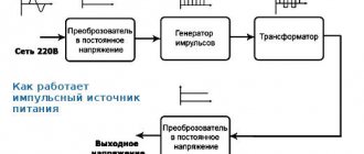
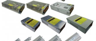
Many amateur radio designs use switching power supplies (PS). They are small in size with significant power. This reduction was made possible due to the high frequency. At such frequencies, you can get a high output voltage with a small number of turns. For example, to obtain a voltage of 12 V at a current of 1 A, you need to wind only five turns. In addition, switching power supplies have a high efficiency, since the losses on the transformer are very small.
These power supplies also have disadvantages: they create high-frequency interference and impose high load requirements. The latter should not be more or less than that for which the power supply is designed.
Network filter circuits for pulsed and high-frequency interference: 4 types of designs
Rule No. 2: high-quality UPSs must have a reliable filter for high-frequency signals in the design of the unit .
It is important to understand that high frequency pulses play a dual role:
- V/h interference can come from the household network to the power supply;
- high-frequency current pulses are generated by the built-in converter and exit it into the home wiring.
Reasons for interference in a household network:
- aperiodic components of transient processes arising from switching powerful loads;
- operation of nearby devices with strong electromagnetic fields, for example, welding machines, powerful traction motors, power transformers;
- consequences of suppressed atmospheric discharge pulses and other factors, including the superposition of high-frequency harmonics.
Interference impairs the performance of electronic equipment, mobile devices and digital gadgets. They must be suppressed and blocked within the switching power supply design.
The filter is based on a choke made of two windings on one core.
Chokes can be made in different sizes, wound with thick or thin wire on large or small cores.
It is enough for a novice master to remember a simple rule: a filter with a large magnetic circuit inductor, an increased number of turns and a wire cross-section works better. (Principle: the more, the better.)
The inductor has inductive reactance, which sharply limits the high-frequency signal flowing through the phase or zero wire. At the same time, it does not have much effect on the current in the household network.
The operation of the inductor is effectively complemented by capacitive reactances.
The capacitors are selected in such a way that they short-circuit the interference signals weakened by the RF choke, directing them to ground potential.
The principle of operation of the filter for high-frequency noise from penetration of input signals into the power supply is shown in the picture below.
Y capacitors are installed between the ground potentials with zero and phase. Their design feature is that in the event of a breakdown they are not capable of creating an internal short circuit and supplying 220 volts to the device body.
Between the phase and zero circuits, capacitors are placed that can withstand 400 volts, or better yet, 630. They are usually shaped like a parallelepiped.
However, you should be well aware that the UPSs in the voltage converter themselves correct the signal and interference practically does not interfere with them. Therefore, such a system is relevant for conventional analog blocks with output signal stabilization.
For a switching power supply, it is important to prevent RF interference from entering the household network. Another solution implements this feature.
As you can see, the principle is the same. It’s just that capacitive reactances are always located along the path of the interference behind the inductor.
The third circuit of the high-frequency filter is considered universal. She combined elements of the first two. The Y capacitors in it simply work on both sides of each inductor.
The most expensive and reliable devices use a complex filter with additionally connected chokes and capacitors.
I immediately show the arrangement of filters on all circuits of the power supply: input and output.
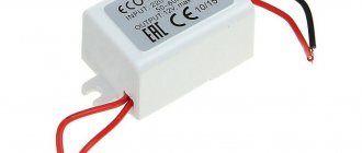
Please note that a ferrite filter, consisting of two detachable half-cylinders or made of a one-piece structure, can be additionally installed on the cable coming out of the UPS and connected to the electronic device.
An example of its use is a switching power supply for a laptop. This is already the fourth use of the filter.
Video about the operation of a switching power supply
Antenna power supply
Coffee capsules Nescafe Dolce Gusto Cappuccino, 8 servings (16 capsules)
435 ₽ More details
Coffee capsule Nescafe Dolce Gusto Cafe O Le Coffee with milk, 3 packs of 16 capsules each
1305 ₽ More details
Continuous scanners
Mains voltage rectifier: the most popular design
Rule No. 3: after the output from the filter, the voltage is supplied to the rectifier circuit , which in the basic version consists of a diode bridge and an electrolytic capacitor.
During the electrical conversion, the shape of a sine wave, consisting of half-waves of opposite signs, first changes to a signal in a positive direction after the diode assembly, and then these pulsations are smoothed out to an almost constant amplitude value of 311 volts.
Such a network voltage rectifier is included in the operation of all power supplies.
Power supply circuit
The circuit of the most common configuration of a pulse converter includes:
- network noise suppression filter;
- rectifier;
- smoothing filter;
- pulse width converter;
- key transistors;
- high frequency output transformer;
- output rectifiers;
- output individual and group filters.
The purpose of the noise suppression filter is to delay interference from the operation of the device into the power supply network. Switching of powerful semiconductor elements can be accompanied by the creation of short-term pulses in a wide range of frequencies. Therefore, here it is necessary to use elements designed specifically for this purpose as pass-through capacitors of the filter units.
The rectifier is used to convert the input alternating voltage into direct voltage, and the smoothing filter installed next eliminates the ripple of the rectified voltage.
In the case when a DC-DC converter is used, the rectifier and filter become unnecessary, and the input signal, after passing through the noise suppression filter circuits, is fed directly to the pulse-width converter (modulator), abbreviated PWM.
PWM is the most complex part of the switching power supply circuit. His tasks include:
- generation of high-frequency pulses;
- control of the block's output parameters and correction of the pulse sequence in accordance with the feedback signal;
- control and protection against overloads.
Pulse voltage converter: explanation in simple words with explanatory pictures
Rule No. 4: the rectified signal is subjected to pulse-width modulation on a power switch under the control of a PWM controller .
The power switch is made by the primary winding of a high-frequency transformer. For effective transformation of high-frequency pulses up to 100 kilohertz, the magnetic core structure is made of alsifer or ferrites.
The transformer winding receives signal pulses of several tens of kilohertz from the control circuits through an RF transistor.
Rectangular current pulses are supplied in time, alternating with pauses, and are designated by one (1) and zero (0).
The duration of the pulse or its width at each moment of low-frequency sinusoidal voltage corresponds to its amplitude: the larger it is, the wider the PWM. And vice versa.
The PWM controller monitors the value of the connected load at the output of the switching power supply. According to its value, it generates pulses that briefly open the power transistor.
If the power connected to the UPS begins to increase, then the control circuit increases the duration of the control pulses, and when it decreases, it decreases.
Due to the operation of this design, the voltage at the output of the unit is stabilized in a strictly defined range.
Types of power supplies
Several types of inverters, which differ in their construction scheme, have found application:
- transformerless;
- transformer
The first ones differ in that the pulse sequence goes directly to the output rectifier and smoothing filter of the device. This scheme has a minimum of components. A simple inverter includes a specialized integrated circuit - a pulse width generator.
The main disadvantage of transformerless devices is that they do not have galvanic isolation from the supply network and can pose a risk of electric shock. They also usually have low power and only produce 1 output voltage.
Pulse transformer: operating principle of one pulse in 2 cycles
Rule #5: The pulse transformer for the power supply transmits each PWM pulse due to two conversions of electromagnetic energy .
During the conversion of electrical energy to magnetic energy and back to electrical energy with reduced voltage, galvanic separation of the primary input circuits from the secondary output circuit is ensured.
Each PWM current pulse arriving when the power transistor is briefly opened flows through the closed circuit of the primary winding of the transformer.
Its energy is spent:
- first to magnetize the magnetic core;
- then to demagnetize it with current flowing through the secondary winding and additional charging of the capacitor.
According to this principle, each PWM pulse from the primary network recharges the storage capacitor.
UPS generators can operate using simple single-cycle or more complex push-pull construction technology.
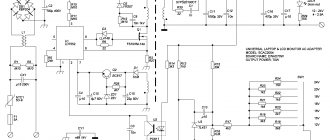
Single-cycle switching power supply circuit: composition and principle of operation
On side 220 there are: a fuse, a rectifying diode bridge, a smoothing capacitor, a bipolar transistor, chains of an oscillating circuit and collector current, as well as windings of a pulse transformer.
A single-cycle switching power supply circuit is created to transmit power of 10÷50 watts, no more. It is used to make chargers for mobile phones, tablets and other digital gadgets.
The rectifier diode D7 is used in the output circuit of the transformer. It can be turned on in the forward direction, as shown in the picture, or reverse, which is important to consider.
When connected directly, the pulse transformer accumulates inductive energy and transfers it to the output circuit to the connected load with a time delay.
If the diode is turned back on, then the transformation of energy from the primary circuit to the secondary circuit occurs during the off state of the transistor.
The single-cycle UPS circuit is characterized by its simplicity of design, but large voltage amplitudes applied to the turns of the primary winding of the pulse transformer.
Their protection is carried out by additional chains of resistors R2÷R4 and capacitors C2, C3.
Push-pull switching power supply circuit: 3 design options
Higher efficiency and reduced power losses are the undeniable advantages of these UPSs compared to single-cycle models.
The simplest version of the full-wave technique is shown in the picture.
If you additionally connect two diodes and one smoothing capacitor to it, then a bipolar circuit is obtained using the same transformer.
It is common in power amplifiers and operates on the flyback principle. In it, smaller currents flow through each capacitor, providing an increased service life of the capacitors during operation.
You can extend the service life of electrolytic capacitors in a UPS by replacing one high-power capacitor with several components. The current will be distributed throughout, which will cause less heating. And heat removal from each individual is better.
The forward-flow power supply circuit has a choke in its design, which performs the function of energy storage. To do this, two diodes direct incoming PWM pulses to its input in the same polarity.
The choke of these devices is made in large dimensions and is installed separately inside the UPS board. It complements the operation of the storage capacitor.
This is clearly visible in the upper form of the signal shown by the rectification oscillogram of the same block without and with a choke.
The forward circuit is used in high-power power supplies, for example, inside a computer.
It uses Schottky diodes to rectify the current. They are used due to:
- reduced voltage drop on direct connection;
- and increased speed when processing high-frequency pulses.
3 diagrams of power stages of push-pull UPSs
In order of complexity of their implementation, generators perform the following:
- half-bridge;
- pavement;
- or the push-pull principle of constructing the output stage.
Half-bridge switching power supply circuit: overview
Capacitors C1, C2 are assembled in series with a capacitive divider. A constant supply voltage is supplied to it and the collector-emitter transitions of transistors T1, T2.
The primary winding of transformer Tr2 is connected to the midpoint of the capacitive divider and transistors. The output voltage of the generator is removed from its secondary winding, which is proportional to the input signal TP1, transformed to the bases T1 and T2.
The half-bridge UPS circuit works for loads ranging from a few watts to kilowatts. Its disadvantage is the possibility of damage to elements during overloads, which requires the use of complex protections.
Bridge Switching Power Supply Circuit: Brief Explanation
Instead of the capacitive divider of the previous technology, transistors T3 and T4 work here. They open in pairs together with T1 and T2: (pair T1-T4), (pair T2-T3).
The voltage of the emitter-collector transitions for closed transistors is not higher than the value of the supply voltage, and on the winding w1 TP3 it increases to the value U supply. Due to this, the efficiency value increases.
The bridge circuit is difficult to set up due to difficulties in setting up the control circuits of transistors T1÷T4.
Push-pull circuit: important features
The primary winding of the output TP2 has a middle terminal, to which the positive potential of the power source is supplied, and its minus is applied to the middle point of the secondary winding T1.
During the passage of one half-cycle of oscillation, one of the transistors T1 or T2 and the corresponding part of the transformer half-winding operate.
Here the highest efficiency, low ripple and low interference are created. The amplitude value of the pulse voltage on any half of the winding w1 TP2 reaches the value U power.
The self-inductive emf is added to the collector-emitter junction voltage of each transistor, and it increases to 2U power supply. Therefore, T1 and T2 must be selected at 600÷700 volts.
The push-pull circuit of the key cascade is more popular. It is used in the most powerful converters.
The advantage of switching power supplies over linear ones
DIY laboratory power supply
Switching-based power supplies offer a number of advantages that distinguish them qualitatively from linear ones. Here are the main ones:
- Significant reduction in dimensions and weight of devices;
- Reducing the amount of expensive non-ferrous metals, such as copper, used in their manufacture;
- No problems when a short circuit occurs, this mostly applies to flyback devices;
- Excellent smooth regulation of the output voltage, as well as its stabilization by introducing feedback into PWM controllers;
- High efficiency indicators.
However, like everything in this world, pulse blocks have their drawbacks:
- Emission of interference that can appear due to faulty noise suppression circuits, most often due to the drying out of electrolytic capacitors;
- Undesirable operation without load;
- A more complex circuit using a larger number of parts, to find analogues of which a reference book is needed.
The use of power supplies based on high-frequency modulation (pulse) in modern electronics, both in everyday life and in production, has significantly influenced the development of all electronic equipment. They have long displaced outdated sources built on a traditional linear circuit from the market, and will only improve in the future. PWM controllers are the heart of this device and the development of their functionality and technical characteristics is constantly improving.
Output Rectifier: The Most Popular Device
Rule #6: The signal coming from the UPS output is rectified and smoothed.
The simplest rectifier circuit, consisting of a diode and a storage capacitor, is shown in the picture below.
It can be modified by connecting additional capacitors, chokes, and filter elements.
Advantages and disadvantages of UPS
Of course, like any other electronic device, such a power supply has both its advantages and disadvantages. Of course, because this power supply is a more high-tech device, there are many more positive qualities in it than negative ones, but there is still a need for an objective consideration, and therefore there is no need to remain silent about the disadvantages. But still, first we will list the advantages, and then we will analyze them in more detail.
The main and undoubted advantages of a switching power supply are:
- lighter weight;
- high efficiency;
- low price;
- wide range of currents;
- the presence of protection from various factors.
We recommend reading: How to make a radio-controlled airplane at home
Well, now let’s look at each point in more detail.
Advantages
- Low weight and dimensions are achieved due to pulse technology, increasing the frequency of the current, and therefore reducing transformer installations. SMPS does not require large radiators and windings. The capacitance of the capacitors has also been reduced. In addition, the rectification circuit is simplified to an elementary one - half-wave.
- Naturally, with transformer power supplies, most of the energy is spent on heating, as a result of which the efficiency decreases. In switching power supplies, a small part of this energy is lost in cascades of power switches. Afterwards, all transistors are stable, and therefore the efficiency of such power supplies can reach 97%.
- The cost of these devices is reduced by expanding the production of elements for assembling such a circuit. Even after they appeared on the market, they were not worth much, but now, when all areas of sales are saturated with them, their cost is falling ever lower. It can be added that it is also possible to use semiconductors that are less powerful thanks to controlled switches.
- A wide range is achieved precisely thanks to pulse technologies. Power supply of different frequencies and amplitudes is allowed, which cannot but affect the expansion of their areas of application.
- Based on the fact that the semiconductor modules are quite small, it becomes possible to integrate additional protection units (against short circuit, overheating, overload, etc.).
Flaws
If the conversation turns to the pros, then you should not ignore the cons, although they are negligible. The main drawback in the operation of switching power supplies can be called high-frequency interference. They are natural, because... the device itself works specifically for them. It is for this reason that various noise reduction is used, which, however, does not completely solve the problem.
Therefore, such UPSs are not used on some high-precision measuring instruments.
Another disadvantage is incorrect operation at ultra-low and ultra-high frequencies - such “stressful” currents can either damage the device, or at the output it will produce a distorted voltage that does not correspond to the declared technical characteristics.
Recommendations for calculating filter capacitors
The input high-voltage capacitor of the low-pass filter is calculated using the formula:
where: P - power consumed from the AC network; UminDC - minimum input rectified voltage; Uzener - limiting voltage of the protective zener diode; Uref—reverse voltage; K is the voltage ripple coefficient on the capacitor.
The output high-frequency filter is designed based on the maximum permissible output voltage ripple and maximum peak current.
For more detailed information regarding filter calculations, see the Datasheet for the specific chip.
Design verification
Before turning on the power supply for the first time, you need to check it. First of all, the installation is checked; for example, traces of soldering or unwashed flux could remain. Any component installed on the board may be faulty.
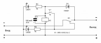
If everything is in order with the installation, you can proceed to the second stage of testing using a light bulb. Any incandescent lamp can be used as a light bulb. To do this, we connect the power supply we made in series with the light bulb, as shown in the figure below.
If the light does not light, it means there is an open circuit in the power supply circuit. You need to check the board tracks, inductor, diode bridge.
The light is constantly on. There is a short circuit in the power supply. The reason may be a breakdown of capacitors or transistors. It is also necessary to check the tracks of the printed circuit board and the output circuits of the transformer.
If the light flashes and goes out, it means the power supply is working and the capacitors are charged.