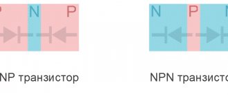
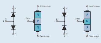
Connection diagrams for a bipolar transistor Circuit designers use the following connection diagrams: with a common base, common emitter electrodes, and connection with a common collector Fig. If the plate has exponent n, then it will be p.
Designed to enhance the power of electromagnetic oscillations. With insulated gate they are divided into: with built-in and induced channel.
Circuits for connecting field-effect transistors Just as in various electronic devices bipolar transistors operate in a common-emitter, common-collector, or common-base circuit, field-effect transistors in many cases can be used in a similar way including them: with a common source, with a common drain or with a common shutter. An induced channel transistor can only operate in enrichment mode. How to test a field-effect transistor using a tester.
The drain-gate characteristic shows the same thing, the differences are again in the voltages at the gate.
Modern devices are practically not afraid of this, since protective devices such as zener diodes can be built into them at the input, which are triggered when the voltage is exceeded. We have obtained a visual model of a bipolar transistor with a pnp structure.
The heating time depends on the temperature of the iron and ranges from 30 to 90 seconds. In Fig.
With an induced channel Transistors with a built-in channel In the diagram you see a transistor with a built-in channel. Types of field-effect transistors When guided by these details of electrical circuits, the following indicators are taken into account: internal and external resistance, cut-off voltage and slope of the drain-gate characteristic.
The source is a source of charge carriers, an analogue of the emitter on a bipolar one.
Drivers for field-effect transistors, the simplest and most common
What is a transistor?
One of their main purposes is to operate in switching mode, that is, the transistor is either closed or completely open when the resistance of the Drain-Source transition is practically zero. Here are the results of modeling such a situation.
The built-in diode turns on in the opposite direction and no current flows through it.
This is possible due to the fact that injection of minority charge carriers is not used. How does a field effect transistor work? The OZ cascade has a low input impedance, and therefore has limited use.
Share with your friends:. Field effect transistor First, let's define the terminology. MOS transistors use silicon oxide SiO2 as a dielectric.
Due to their design features, MOSFETs are extremely sensitive to external electric fields. 5 CIRCUITS on ONE FIELD (MOS, MOS, MOSFET) TRANSISTOR 2N65F
Read more: How to make an estimate for electrical work
Pulse devices
How is a pulsed electronic load made? First of all, experts recommend choosing a good thyristor for assembly. In this case, the modulator is suitable only for two phases. Experts say that the expander should work alternately. Its operating frequency must be approximately 4000 kHz. The transceiver is installed into the load through a modulator. After soldering the capacitors, it’s worth working on the amplifier.
For stable operation of the load, three channel-directional filters are required. A tester is used to check the device. The resistance should be approximately 55 ohms. Under average load, a homemade electronic load produces a rated voltage of around 200 W. Comparators are used to increase sensitivity. When the system shorts, it is worth checking the circuit from the capacitor. If the resistance at the contacts is too low, then the transceiver needs to be replaced with a capacitive analogue. Many experts point to the possibility of using wave filters that have good conductivity. Regulators for these purposes are used on a triode.
Types of transistors
Each branch differs by 0.
Image of field triode wiring diagrams Almost every circuit is capable of operating at very low input voltages. MOSFET connection circuit The traditional, classic connection circuit of a “mosfet” operating in the open-close switch mode is shown in Fig. 3.
Tests have shown that the transistor switch works perfectly, supplying voltage to the load. Transistors are voltage controlled and do not consume control current in static conditions.
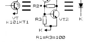
If a voltage is applied to such a transistor, plus to the drain and minus to the source, a large current will flow through it, it will be limited only by the channel resistance, external resistances and internal resistance of the power source. This means that you need to avoid this by introducing a stage with a high input impedance. Among them are: bipolar transistors with embedded resistors and their circuitry; combinations of two triodes of the same or different structures in one package; lambda diodes - a combination of two field-effect triodes forming a section with negative resistance; designs in which a field-effect triode with an insulated gate drives a bipolar triode are used to control electric motors. To prevent the alternating voltage component from being released across the resistor Ri, it is shunted with a capacitor Ci.
The common source cascade gives a very large current and power amplification. The potential difference reaches a value from 0.3 to 0.6 V. Only the arrows on the conventional image of field-effect transistors have the direction exactly opposite to their bipolar counterparts.
This means that you need to avoid this by introducing a stage with a high input impedance. Stability under temperature changes. At a certain voltage Uс, the channel narrows, at which the boundaries of both pn junctions narrow and the channel resistance becomes high. This is possible due to the fact that injection of minority charge carriers is not used.
Principle of operation of a triode When the base is de-energized, the transistor very quickly returns to its original state and the collector junction closes. Therefore, the use of this approach in practice is strongly limited in amplification technology.
An oscillation amplifier is also connected here. The gate function is performed by a metal lead, which is separated from the crystal by a layer of dielectric and, thus, is not in electrical contact with it. Reverse polarity protection based on field-effect transistor
Modification scheme
A standard load circuit includes resistors, a rectifier, and modulator ports. If we consider low-frequency devices, they use transceivers. These elements operate on open contacts. Comparators are used to transmit the signal. Recently, loads on stabilizers have become popular. First of all, they are allowed to be used in DC networks. They undergo a rapid transformation process. It is also worth noting that an amplifier and regulator are considered an integral element of any load. These devices are short-circuited to the plate. They have quite high conductivity. The modulator is responsible for the generation process in models.
Field effect transistor
When boron is added, acceptor doped silicon will become a semiconductor with hole conductivity p-Si, that is, its structure will be dominated by positively charged ions. This is the main difference from a practical point of view from bipolar transistors, which are controlled by current.
The figure shows a field-effect transistor with a p-type channel and a gate made of n-type regions. Let's describe each modification in more detail.
If you change the value of the control current, the intensity of hole formation on the base will change, which will entail a proportional change in the amplitude of the output voltage, while maintaining the signal frequency. Among them are: bipolar transistors with embedded resistors and their circuitry; combinations of two triodes of the same or different structures in one package; lambda diodes - a combination of two field-effect triodes forming a section with negative resistance; designs in which a field-effect triode with an insulated gate drives a bipolar triode are used to control electric motors. As it increases, the p-n junctions expand, the cross-sectional area of the current-carrying channel decreases, its resistance increases, and, consequently, the current in the channel decreases.
Only the arrows on the conventional image of field-effect transistors have the direction exactly opposite to their bipolar counterparts. The device of a field-effect transistor with a control pn junction is shown in Fig.
See also: Connect electricity to the site
Other popular articles
Transistors come in different packages, with different numbers of terminals; often two transistors are combined in one package. The transistor has three terminals: source, drain, gate. Vgs - control voltage, Vg-Vs.
This principle is used to amplify signals. In a specific diagram, this p-channel gate device is an n-layer, has a lower resistivity than the p-layer channel region, and the pn junction region is more located in the p-region for this reason.
Related publications
Types of field-effect transistors and their schematic designation. As a result, uncompensated charges arise: in the n-type region - from negative ions, and in the p-type region from positive ions. Circuit with a common source The source is the electrode through which the main charge carriers enter the channel. With a common drain in. MIS transistors are of two types - with a built-in channel and with an induced channel.
The electron-hole pn junction in such field-effect transistors is called the control junction, since it directly changes the power of the flow of charge carriers, representing a physical obstacle to electrons or holes, depending on the type of conductivity of the main crystal. And even vice versa, its presence is specifically used in some schematic solutions. Field-effect transistors are very common in both old and modern circuitry. Field-effect transistor circuits
Programmable Models
The electronic programmable load is quite simple to assemble. For this purpose, a 230 V expansion transceiver is used. Three contactors are used to transmit the signal, which extend from the transistor. Regulators are used to control the conversion process. Linear analogues are most often used. The triode is used with an insulator. In this case, you will need a blowtorch. The resistor is directly fixed to the transceiver.
Conventional comparators, which have a low dissipation coefficient, are definitely not suitable for the model. It is also worth noting that many people make the mistake of installing one filter. For normal operation of the Prior, only capacitive analogues are used. The rated output voltage should be approximately 200 V with a resistance of 40 ohms. If you assemble devices using a single-junction expander, then linear models are not suitable.
First of all, the device will not work due to the large overload of the thyristor. It is also worth noting that the model will require a horizontal modulator with low sensitivity. Some experts use stabilizers during assembly. If we are considering a simple modification, then an adjustable type will do. However, inverting elements are most often used.
Model with continuously adjustable current
The electronic load circuit with continuously adjustable current includes one thyristor. Capacitors for the model will require expansion type with low conductivity. It is also worth noting that one amplifier is placed in the load. The most commonly used are wave analogues that have a phase adapter. The regulator itself is installed behind the modulator, and the rated voltage should be about 300 W.
A simple electronic load with continuously variable current has two contactors for connection. Thyristors can sometimes be used on plates. Comparators in devices are installed with or without stabilizers. In this case, much depends on the operating frequency. If this parameter exceeds 300 kHz, then it is better not to install a stabilizer. Otherwise, the dispersion coefficient will increase significantly.
100 W models
An electronic load (circuit shown below) of 100 W involves the use of two channel thyristors. The transistor in models is quite often used on an expansion basis. Its conductivity is about 5 microns. It is also worth noting that there are loads on the relay. They are most suitable for powerful power supplies. For self-assembly, wave comparators are additionally used. Homemade devices produce a voltage of no more than 300 V, and the operating frequency starts from 120 kHz.
Models for 10 A units
The electronic load for a 10 A power supply is collected using an expansion thyristor. Transistors are quite often used at 5 pF, which have low conductivity. It is also worth noting that experts do not recommend using linear analogues. They have low sensitivity. They greatly increase the dissipation coefficient. Contactors are used to connect to the block. Modulators are quite often used with adapters.
If we consider the circuit on a capacitor block, then their frequency is on average 400 kHz. In this case, sensitivity may change. Contactors are quite often fixed behind the modulator. Stabilizers should be used on two plates. It is also worth noting that to assemble the modification you will need a pole resistor. It greatly helps to increase the speed of impulse generation.
ITECH series models
The loads of this series are distinguished by their high conductivity. They have good security. In this case, several transceivers are used. The electronic load for the power supply operates at an average frequency of 200 kHz. The overload in this case is 4 A. Amplifiers in the devices are used with contact adapters. Thyristors are used of phase or code type. Among the models in this series there are programmable modifications. They are well suited for testing computer power supplies. Transceivers can be found with or without expanders.
Device diagram for 20 A units
The electronic load (circuit shown below) for 20 A units is based on binary resistors. They maintain stable high conductivity. The sensitivity is approximately 6 mV. Some modifications are distinguished by a high overload parameter. Relays in models are used on wave transistors. Comparators are used to solve conversion problems. Expanders are often found in the phase type. And they may have several adapters. If necessary, the device can be assembled independently. For this, a capacitor unit is used.
The rated voltage of homemade loads starts from 300 W, and the average frequency is 400 kHz. Experts do not recommend using transient comparators. Regulators are used with plates. To install the comparator you will need an insulator. If we consider loads on two thyristors, then filters are used there. On average, the module capacitance is 3 pF. The dispersion rate for homemade models starts at 50%. When assembling the device, special attention should be paid to the adapter for connecting to the power supply. Contactors are of the pole type. They must withstand heavy overloads and not overheat.
How to make a 300 W device?
An electronic load of 300 W involves the use of two phase-type thyristors. The rated voltage of the devices is approximately 230 W. The overload indicator in this case depends on the conductivity of the comparator. When assembling this device yourself, you will need a channel-type modulator. A blowtorch is used to install the element.
Regulators are often used with an adapter. The relay is installed as a low-impedance type. The dispersion coefficient of a homemade modification is approximately 80%. It is also worth noting that the contactors used are of low sensitivity. How to check the load before turning it on? This can be done using a tester. The output voltage of homemade devices is usually 50 ohms. If we consider models with one comparator, then this parameter may be underestimated.
Laboratory modifications
Assembling a laboratory electronic load with your own hands with a powerful thyristor. Resistors are used with a capacity of 40 pF or more. Experts say that capacitors can only be used of the expansion type. When assembling, special attention should be paid to the modulator. If you use a wired analogue, then the load will require three filters. A simple electronic load has a phase-type modulator with a conductivity of 30 μm. The resistance is approximately 55 ohms. It's also worth noting that loads are often stacked on top of a switched transceiver. The main feature of such devices lies in high pulsation. In this case, conductivity is ensured at around 30 microns.
Devices for 15 A units
The most common loads are for 15 A units. They use open resistors. In this case, transceivers are used with different polarities. In addition, they differ in sensitivity. On average, the voltage of the devices is 320 V. The models differ in conductivity. For the purpose of self-assembly, comparators are used on regulators. Before installing them, stabilizers are attached.
Experts say that expanders can only be installed through the lining. The conductivity at the input must be no more than 6 microns. When installing the regulator, the comparator is thoroughly cleaned. If you assemble a simple model, then the modulator can be used of the inverter type. This will greatly increase the dispersion coefficient. The threshold voltage is on average 200 V. The permissible power parameter is no more than 240 W. It is also worth noting that different types of filters are used for the load. In this case, much depends on the conductivity of the comparator.
AMETEK devices
Loads of this brand are distinguished by low conductivity. They are great for 15 A power supplies. Among the models of this company there are many pulse modifications. Their specific overload is not high, but they provide a high pulse generation rate. Experts primarily note the good protection of the elements. They use several filters. They cope with phase interference that distorts signals.
If we consider high-frequency models, they have several thyristors. It is also worth noting that modifications based on wired comparators are available on the market. Based on the usual load of this brand, you can assemble an excellent device for different power supplies. The models have excellent stabilizers and very sensitive transistors.