This whole thing sometimes needs repairs (a broken wire inside the cable or a bend near the plug), and it’s not always possible to buy a new one. And when you disconnect all the wires from the computer during routine cleaning, doubt may arise “what was stuck where.”
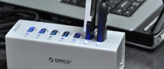
In order to once and for all put together all the necessary and comprehensive information on pinouts, pinouts and the purpose of all sockets/plugs - edition 2 of Schema.ru has prepared this reference material. The tables below show the pinout and pinout of internal and external connectors of a personal computer and laptop.
Computer power supply
AT format PSU connector pinout
Pinout of ATX power supply connector
Pinout of additional power connectors: ATX connectors, SerialATA (or simply SATA, for connecting drives and hard drives), Connectors for additional processor power, Connector for floppy drive, MOLEX (for connecting hard drives and drives):
Another variant:
Another option for PSU video cards:
- Read more about the pinout of computer power connectors here
Types of connectors for powering PC components
The shape and position of the connectors of the internal power supply of personal computers is regulated by the ATX standard, which replaced the outdated AT. To connect devices to a source of electrical energy, the following are mainly used:
- ATX 20 (20+4, 24) – for power supply to the motherboard;
- 4 or 8 pin connector – for powering the processor;
- Molex – for powering many peripheral devices;
- SATA power – for powering hard or solid-state drives;
- PCI Expess – for powering video cards.
You can also find other connectors inside the PC. Some are obsolete and rare (for example, to power floppy drives), others are just gaining popularity.
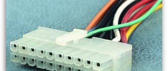
For motherboard (ATX 20, 24 pin)
The largest connector coming from the power supply is connected to the motherboard. It contains 24 sockets (there are 24 pins on the board, respectively). You can also find power connectors for older computers with 20 pins. The pinout and color marking of the 24-pin connector is shown in the figure.
Pin assignment of the ATX 24 connector.
Some channels are signal and are used to control the power supply:
- pin 8 - Power OK (PWR_OK, PWR_good) - signal to the motherboard “power is on”;
- pin 16 -Power ON – signal from the motherboard, permission to supply voltage, in standby mode it is +5 volts (pulled up by a resistor), in enable mode – 0 volts (on the motherboard it is connected to the common wire);
- pin 13 additional brown wire - Sense - feedback for automatic voltage regulation.
You should also separately note the Stand by voltage on the purple wire (pin 9). It is designed to power the internal power supply circuit and at the same time serves as a standby voltage to start the computer.
The 20-pin connector lacks a section of the 4 outer pins - pairs 11-12 and 23-24. In the new 24-pin connector, this section can be made removable.
Motherboard connector 20+4.
Fan connector pinout
- Read more about connecting coolers from processors, video cards and power supplies at the link
Installing an additional video card connector in the computer's power supply
Sometimes there are seemingly hopeless situations. For example, you bought a modern video card and decided to install it in your computer. There is the necessary slot on the motherboard for installing a video card, but there is no suitable connector on the wires for additional power supply to the video card coming from the power supply. You can buy an adapter, replace the entire power supply, or you can independently install an additional connector on the power supply to power the video card. This is a simple task, the main thing is to have a suitable connector, it can be taken from a faulty power supply.
First you need to prepare the wires coming from the connectors for the offset connection, as shown in the photo. An additional connector for powering the video card can be connected to the wires going, for example, from the power supply to drive A. You can also connect to any other wires of the desired color, but in such a way that there is enough length to connect the video card, and preferably nothing to them was no longer connected. The black wires (common) of the additional connector for powering the video card are connected to the black wire, and the yellow wires (+12 V), respectively, to the yellow wire.
The wires coming from the additional connector for powering the video card are tightly wrapped with at least three turns around the wire to which they are connected. If possible, it is better to solder the connections with a soldering iron. But even without soldering, in this case the contact will be quite reliable.
The work of installing an additional connector for powering the video card is completed by isolating the connection point, several turns, and you can connect the video card to the power supply. Due to the fact that the twisting points are located at a distance from each other, there is no need to isolate each twist separately. It is enough to cover only the area where the wires are exposed with insulation.
Audio connectors
The number of these connectors may vary. In addition, they can be duplicated on the computer and located both at the back of the case and on the front panel. These connectors are usually made in different colors.
- Light green – used to connect one pair of stereo speakers.
- Pink – microphone connection.
- Blue – line input for connecting other audio devices and recording sound from them to a computer.
At the same time, if you have two or three green connectors on your computer, you can simultaneously connect speakers and headphones to them and in the computer settings choose which device to output sound to. Sound card software may provide the ability to override the audio jack assignments. Sound connectors of other colors are used to connect additional speakers.
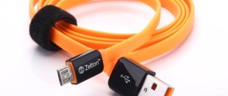
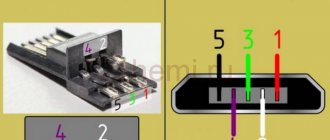
Useful: Micro USB connector pinout
What adapters may be needed
When upgrading a computer or during initial assembly, it may turn out that the power supply does not have the necessary connectors for connecting peripheral devices, and it is not possible to select a power supply with all the necessary connectors. In this case, adapters from one type of connecting terminal to another will help out. So, if instead of an outdated hard drive with power via a Molex connector, a new device made according to the SATA standard is installed, you will need a harness with two connectors: Molex on one side, SATA-Power on the other.
Molex to SATA adapter.
If the power supply has unused SATA connectors, they can be used to power high-performance video cards. To do this you will need an appropriate adapter.
Adapter from 2xSATA to 8-pin.
If the motherboard has a connector for powering the VRM (processor) with 8 pins, and the power supply has a connector designed for 4 (and vice versa), you can also purchase a special adapter harness. But you don’t have to buy it - these connectors are fully compatible and fit perfectly together without adapter cables.
If the connector for the motherboard on the power supply contains 20 pins, and on the power supply - 24 (and vice versa), then a harness with two connectors will also help here.
Adapter for motherboard 20-24.
These are the main adapter cables. During the computer assembly process, you may need other adapters. All of them are available for sale.
Data connectors (Southbridge)
IDE (Integrated Drive Electronics)
It is correctly called – ATA/ATAPI – Advanced Technology Attachment Packet Interface, used to connect hard drives and drives.
SATA and eSATA connectors
The same thing, the only difference is in the shape of the connector, this is a data connector for connecting hard drives and drives.
DVD slim sata
DVD slim sata (mini sata standard pinout).
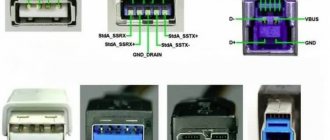
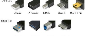
Pinout of USB connectors in a PC
Pinout of USB connectors 1.0-2.0 (Universal Serial Bus).
USB 2.0 Series A, B and Mini
USB 2.0 Micro USB
USB 2.0 on motherboard
Motherboard connector pinout for USB 2.0 front panel
USB 3.0 connector diagram
Pinout of USB 3.0 connectors (Universal Serial Bus).
USB 3.0 Series A, B, Micro-B and Powered-B. The Powered-B series differs from the B series in that it has 2 additional pins available that serve to transmit additional power, thus the device can receive up to 1000 mA of current. This eliminates the need for an additional power source for low-power devices.
USB 3.0 on motherboard
Motherboard connector pinout for USB 3.0 front panel
- Read more about micro USB here
Reference table of color markings, voltage values and ripple range on power supply connectors
Wires of the same color coming out of the computer's power supply are soldered internally to one track of the printed circuit board, that is, connected in parallel. Therefore, the voltage on all wires of the same color is the same value.
| Table of color marking of wires, output voltages and ripple range of ATX power supply | |||||||
| Output voltage, V | +3,3 | +5,0 | +12,0 | -12,0 | +5.0 SB | +5.0 PG | GND |
| Wire color coding | orange | red | yellow | blue | violet | grey | black |
| Permissible deviation, % | ±5 | ±5 | ±5 | ±10 | ±5 | – | – |
| Permissible minimum voltage | +3,14 | +4,75 | +11,40 | -10,80 | +4,75 | +3,00 | – |
| Permissible maximum voltage | +3,46 | +5,25 | +12,60 | -13,20 | +5,25 | +6,00 | – |
| Ripple range no more than, mV | 50 | 50 | 120 | 120 | 120 | 120 | – |
Voltage +5 V SB (Stand-by) – (purple wire) is generated by an independent low-power power supply built into the power supply unit, based on one field-effect transistor and a transformer. This voltage ensures the computer operates in standby mode and serves only to start the power supply. When the computer is running, the presence or absence of +5 V SB voltage does not matter. Thanks to +5 V SB, the computer can be started by pressing the “Start” button on the system unit or remotely, for example, from an uninterruptible power supply unit in the event of a prolonged absence of 220 V supply voltage.
Voltage +5 V PG (Power Good) - appears on the gray wire of the power supply unit after 0.1-0.5 seconds if it is in good condition after self-testing and serves as an enabling signal for the operation of the motherboard.
When measuring voltages, the “negative” end of the probe is connected to the black wire (common), and the “positive” end is connected to the contacts in the connector. You can measure output voltages directly while the computer is running.
A voltage of minus 12 V (blue wire) is only needed to power the RS-232 interface, which is not installed in modern computers. Therefore, in power supplies of the latest models this voltage may not be present.
The deviation of the supply voltages from the nominal values should not exceed the values given in the table.
When measuring the voltage on the wires of the power supply, it must be connected to a load, for example, to a motherboard or a homemade load block.
AT keyboard pinout
Colors among PC manufacturers are not unified. For example, some may have a purple keyboard connector, while others may have a red or gray one. Therefore, pay attention to the special symbols that mark the connectors. These connectors are used to connect a mouse (light green connector) and a keyboard (lilac connector). There are cases when there is only one connector, half painted light green, the other half lilac - then you can connect both a mouse and a keyboard to it.
Basic pinout diagrams
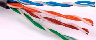
To complete the operation successfully, it is necessary to correctly position the existing wires in the RJ-45 connector. There are several wiring diagrams: direct (pinout of an Internet cable with 8 wires) and cross.
Direct pinout diagram for 8 wires
The first is marked 568B, the second - 568A. Using the direct method, you can connect the router to a personal computer or other device. It is advisable to use the second scheme to connect several computers (or laptop-PC) directly.
Important! Usually the direct method of connecting the cable to the connector is used.
Pinout COM, LPT, GAME, RJ45, PS/2
Pinout of COM, LPT, GAME, RJ45, PS/2 ports and plug circuit (COM, LPT).
Plug diagram for testing a COM port.
IEE 1394 layout on the motherboard
IEEE 1394 is a high-speed serial data bus. Various companies use the brands Firewire for Apple, i.LINK for SONY, etc. for its name. Apple had a hand in the development. At its core, the connector is similar to USB. This port, apparently, will not be widely used due to licensing payments for each chip for this port in favor of Apple.
For CPU
Processor performance has been steadily increasing in recent decades. Their energy consumption is also growing. The processors are powered by voltage converters (VRMs) installed on the motherboard. About two decades ago, there was a massive transition in VRM power supply from +5 volts to +12 volts. This is due to the fact that less current is required to transmit the same power at a higher voltage. VRMs receive power via a separate cable with a 4-pin connector. Two contacts are for +12 volts (yellow wire) and two are for ground (black insulated wire).
Connector for VRM 4 pins.
The sockets on the connector and the pins on the board are arranged in two rows according to their intended purpose. Two pins serve as a key - their shape is different from the others, so an erroneous connection is impossible.
Pinout of 4-pin connector for VRM.
As productivity increased, the number of VRMs began to grow (first on servers, then on personal computers), so the question arose about rational power distribution. The issue was resolved by using 8-pin connectors. In them, the supplied power is distributed over 4 pairs of conductors.
Connector for VRM 8 pins.
Otherwise, there are no fundamental differences from the previous version. The connector contains two rows of sockets - +12 volts and 0 volts, only 4 in a row.
Pinout of 8-pin connector for VRM.
Progress cannot be stopped; energy consumption by processors will only increase. It looks like 4-pin connectors have outlived their usefulness and are becoming a thing of the past.
For video card (PCI Express)
Video cards of previous generations, which have low performance, and modern budget-class models are powered by the PCIe x 16 connector to which they are connected. The voltage to this terminal comes from the motherboard, which, in turn, is powered from the power supply through a 24(20)-pin connector. This is enough to transmit 75 watts.
PCI Express additional power connector.
This is not enough for modern high-performance cards, so they are provided with an additional PCI Express power input. Initially, it was a 6-pin connector and allowed for additional power supply of 75 watts. Very soon this bandwidth was not enough, and subsequent ATX standards were supplemented by an 8-pin connector and 120 watts.
Pinout of 6-pin and 8-pin connector.
This connector is also available in a universal 6+2 format, allowing it to be used for both 6-pin and 8-pin video card connectors.
Universal connector 6+2.
For the most modern video cards, manufacturers use connectors with twelve pins , but they are not yet widely used.
For hard drives and other devices (SATA, MOLEX)
To connect hard drives and some other peripherals, the Molex connector (named after the manufacturer) has been used for a long time. Its advantage is that it has plugs and sockets with large, powerful contacts that operate reliably at high currents.
The plug-in elements are arranged in one row. The connector also has a key to prevent incorrect connections. The two inner pins are for ground wires (black). Conductors with a voltage of +5 volts and +12 volts are connected to the extreme ones. Each contact is designed for a current of 11 amperes, which allows you to transmit 55 watts through a five-volt channel, and 132 watts through a twelve-volt channel. The pinout of the Molex connector is shown in the figure.
Molex connector pinout.
The power transmitted along the power line is limited not only by the load capacity of the connector, but also by the cross-section of the wires of the connected cable, the width of the printed circuit board tracks, etc. To determine the highest power of the line, it is necessary to select the capabilities of the least powerful component.
Due to the increased popularity of the SATA standard, Molex connectors are being replaced by SATA power connectors, which have 15 outputs. 3 pins are used for each voltage, which allows you to transmit more power without increasing the cross-section of the conductors and maintaining the flexibility of the cable. The voltage groups are separated by groups of neutral wires (3 conductors each). The connector pinout is in the table.
| Contact number | Wire color | Voltage level, V |
| 1 | Orange | +3,3 |
| 2 | Orange | +3,3 |
| 3 | Orange | +3,3 |
| 4 | Black | 0 V |
| 5 | Black | 0 V |
| 6 | Black | 0 V |
| 7 | Red | +5 |
| 8 | Red | +5 |
| 9 | Red | +5 |
| 10 | Black | 0 V |
| 11 | Black | 0 V |
| 12 | Black | 0 V |
| 13 | Yellow | +12 |
| 14 | Yellow | +12 |
| 15 | Yellow | +12 |
The SATA standard involves connecting devices with two connectors - for power and for data transfer. They should not be confused.
SATA power connector.
Data connectors (Northbridge)
For more information about PCI connectors, please follow the link, it also includes the pinout.
PCI Express: x1, x4, x8, x16
If you seal the extra contacts, the PCI Express video card will operate in only x1 PCI Express mode. Bandwidth is 256 MB/s in both directions.