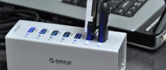
In every computer and other similar devices, the most popular is the USB connector. Using a USB cable, it became possible to connect more than 100 units of series-connected devices. These buses allow you to connect and disconnect any devices even while the personal computer is running. Almost all devices can be charged through this connector, so there is no need to use additional power supplies. USB pinout colors help you determine exactly what type of device a particular bus belongs to.
What is pinout
The pinout of a USB connector is the order in which the necessary elements are placed in the plug using a special serial bus in its various variants.
These days, USB is the most famous interface, which was created in 1996. This model was created with the aim of connecting various devices to a computer and so that it could replace outdated models.
Every year, information about the creation of such a wire spread around the world more and more. Now it’s difficult for us to imagine any other version of the charger.
Of course, some companies still do not use the USB circuit for their models, but most companies still prefer this option.
Nowadays everyone uses USB to transfer data from electronic media and as a charger. To carry out high-quality pinouts, you will need a lot of knowledge, which consists of understanding various types of circuits, orientation in connections, knowledge of wire typology, etc.
What to do if the contacts are poorly soldered
If problems arise while soldering the contact terminals (for example, the solder is not removed or continuous “snot” appears), then you can help with a hairdryer. That is, we heat the board from above by 100 - 150 °C so that the board warms up and the solder is easier to remove. And the temperature of the soldering iron should not be higher than 350 °C, otherwise the contact pins may overheat.
Restoring contacts
If the contact pads were torn off or overheated during the replacement procedure, they can be restored using thin wires. To do this, you need to find control points on the board or tracks and solder wire to them. As a wire, you can use the braid from the coaxial cable of a mobile device or a coil from a broken speaker. It is important to solder the wire not too thick, but not too thin and that it in no case be like a guitar string.
After restoring the contacts, it is best to strengthen the soldering area. This can be done using so-called red glue or, more simply, compound.
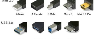
Types of USB connectors, main differences and features
The Universal Serial Bus comes in 3 versions - USB 1.1, USB 2.0 and USB 3.0. The first two specifications are completely compatible with each other; bus 3.0 is partially compatible.
USB 1.1 is the first version of the device used for data transfer. The specification is used only for compatibility, since 2 operating modes for data transfer (Low-speed and Full-speed) have a low speed of information exchange. Low-speed mode with a data transfer rate of 10-1500 Kbps is used for joysticks, mice, and keyboards. Full-speed is used in audio and video devices.
A third operating mode has been added to USB 2.0 - High-speed for connecting information storage devices and video devices of a higher organization. The connector is marked with HI-SPEED on the logo. The information exchange speed in this mode is 480 Mbit/s, which is equal to the copy speed of 48 MB/s.
In practice, due to the design and implementation features of the protocol, the throughput of the second version turned out to be less than declared and amounts to 30-35 MB/s. The 1.1 and 2nd generation Universal Bus specification cables and connectors are identical in configuration.
The third generation universal bus supports a speed of 5 Gbps, equal to a copy speed of 500 MB/s. It is available in blue, which makes it easier to determine whether the plugs and sockets belong to the advanced model. Bus 3.0 current increased from 500 mA to 900 mA. This feature allows you not to use separate power supplies for peripheral devices, but to use the 3.0 bus to power them.
Compatibility of specifications 2.0 and 3.0 is partially achieved.
Classification and pinout
When describing and designating tables of USB connectors, it is accepted by default that the view is shown from the outside, working side. If the view is from the installation side, this is specified in the description. In the diagram, the insulating elements of the connector are marked in light gray, the metal parts are marked in dark gray, and the cavities are marked in white.
Despite the fact that the serial bus is called universal, it is represented by 2 types. They perform different functions and provide compatibility with devices with improved characteristics.
Type A includes active, power supply devices (computer, host), type B includes passive, connected equipment (printer, scanner). All sockets and plugs of the second generation and version 3.0 type A buses are designed to work together. The Gen3 Type B jack connector is larger than what is needed for the 2.0 Type B plug, so a device with a Gen 2.0 Type B connector is connected using only a USB 2.0 cable. Connection of external equipment with modification 3.0 type B connectors is carried out using cables of both types.
Classic Type B connectors are not suitable for connecting small electronic equipment. Connecting tablets, digital equipment, and mobile phones is done using miniature Mini-USB connectors and their improved Micro-USB modification. These connectors have reduced plug and socket sizes.
The latest modification of USB connectors is type C. This design has identical connectors at both ends of the cable and is characterized by faster data transfer and greater power.
Necessary parts, tools and consumables
To achieve high-quality work and improve your skills, you need to try all available methods and tools. Therefore, first, decide which method will be easier for you, and only then proceed to selecting tools and consumables.
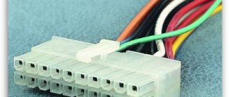
USB connectors
Manufacturers produce different types of connectors in terms of mounting and number of contacts. You can find out exactly what is faulty in your device only after opening it. New connectors are sold in radio stores and stores selling spare parts for telephones individually. It is best to buy a whole set of connectors from an online store, for example, AliExpress. Sellers sell the most popular types in whole packs, so it’s better to buy in bulk, especially if you plan to continue doing such repairs.
Tools
Actually, to replace USB, we need a soldering iron or soldering station itself. Lukey 702 and similar analogues are perfect. You can get by with just one soldering iron, but more on that below. You may also need pliers and wire cutters if you do not have the connector required for the body contacts. You also need the simplest tweezers to remove parts.
Consumables
Thermal tape (or aluminum), desoldering braid, flux (simple RMA223 will do), PIC solder, and also Rose alloy. And a cleaning agent (for example, galosh gasoline, isopropyl alcohol or FLUX OFF).
What are the advantages of Universal Serial Bus?
The introduction of this connection method made it possible:
- Quickly connect various peripheral devices to your PC, from the keyboard to external disk drives.
- Make full use of Plug&Play technology, which simplifies the connection and configuration of peripherals.
- Refusal of a number of outdated interfaces, which had a positive impact on the functionality of computing systems.
- The bus allows not only to transfer data, but also to supply power to connected devices, with a load current limit of 0.5 and 0.9 A for the old and new generations. This made it possible to use USB to charge phones, as well as connect various gadgets (mini fans, lights, etc.).
- It has become possible to manufacture mobile controllers, for example, a USB RJ-45 network card, electronic keys for entering and exiting the system
It will be interesting➡ The gimlet rule
Mini USB pinout
This connection option is used only in early versions of the interface; in the third generation this type is not used.
Mini USB connector pinout
As you can see, the wiring of the plug and socket is almost identical to the micro USB, respectively, the color scheme of the wires and the contact numbers are also the same. Actually, the differences are only in shape and size.
In this article we have presented only standard types of connections; many manufacturers of digital equipment practice introducing their own standards; there you can find connectors for 7 pin, 8 pin, etc. This introduces certain difficulties, especially when the question arises of finding a charger for a mobile phone. It should also be noted that products are in no hurry to tell how the USB pinout is done in such contactors. But, as a rule, this information is easy to find on thematic forums.
Bottom line
We examined in detail several methods for replacing the USB connector on mobile devices yourself. It may seem difficult at first glance, but everything comes with experience. The main rules are that you don’t need to rush, tear out the connector from the board prematurely, and don’t fry the board.
The methods described above are also suitable for replacing micro USB on a tablet yourself; there are no fundamental differences.
Cost of work
In various service centers, the price for this work on average starts from 500 rubles. The price may be higher due to complex disassembly (for example, unsticking the display module, the service takes responsibility), guarantees after the replacement procedure, as well as the complexity of the work performed (torn off tracks and pieces of the board).
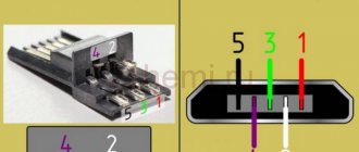
Micro USB connector pinout
To begin with, we present the wiring for this specification.
Micro USB v 2.0 connector wiring
As can be seen from the figure, this is a 5 pin connection; both the plug (A) and socket (B) have four contacts. Their purpose and digital and color designation correspond to the accepted standard, which was given above.
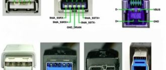
Description of the micro USB connector for version 3.0.
For this connection, a characteristically shaped 10 pin connector is used. In fact, it consists of two parts of 5 pin each, and one of them fully corresponds to the previous version of the interface. This implementation is somewhat confusing, especially considering the incompatibility of these types. Probably, the developers planned to make it possible to work with connectors of earlier modifications, but subsequently abandoned this idea or have not yet implemented it.
It will be interesting➡ What is the difference between an RCD and a difavtomat
MicroUSB connector layout for version 3.0
The figure shows the pinout of the plug (A) and the appearance of the micro USB socket (B).
Contacts 1 to 5 fully correspond to the second generation micro connector, the purpose of the other contacts is as follows:
- 6 and 7 – data transmission via high-speed protocol (SS_TX- and SS_TX+, respectively).
- 8 – mass for high-speed information channels.
- 9 and 10 – data reception via high-speed protocol (SS_RX- and SS_RX+, respectively).
Replacing the plug on the charger
If the charger is working properly, then for repair you just need to find or buy a micro USB plug for soldering.
The repair will consist of the following:
- cut the wire of the charger and donor cord so that the first one has a tail of 10 cm, and the second one of 15 cm;
- remove the outer insulation 3 cm from the edge. Take care not to damage the coating of the internal cores. To do this, first make a circular (across) and then a longitudinal (lengthwise) cut. Remove the rubber with your fingers and release two veins;
- do the same with the tail of the new plug. You will see 4 wires, an aluminum shield and a copper braid. You only need the red and black vein, everything else can be cut off;
- To prevent a short circuit, shorten the red wire on one part and the black on the other. This will also avoid the bump;
- connect the exposed parts and insulate.
You can use electrical tape, heat shrink or tape. The wires can be simply twisted or soldered; soldering, of course, is more reliable.
If heat shrink tubing is used, bend the connections along the wire and close them. A hairdryer is brought to the material and gently heated. The use of a lighter is allowed, but it must be brought gradually. After this, a wide tube is placed on the main cable. At this point the repair can be considered complete.
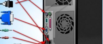
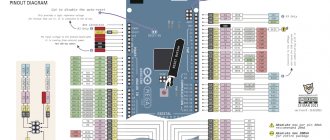
USB pinout on motherboard
USB on the motherboard allows external sources to connect and exchange data with each other.
The problem here is that there is no specific connector layout, since each motherboard is different in this regard.
The motherboard can use both USB 2.0 and 3.0 specifications. The latter is more advanced and is found in newer motherboards.
USB 2.0 is considered more accessible, so it will always be on the motherboard.
A little further we will look at the pinouts of USB 2.0 and 3.0 separately.
USB 2.0 can be converted to 3.0. The diagram shows that in order to implement this idea, you need to connect the contacts correctly. We connect the red contacts (+5V) 2.0 in this order:
- 1 (USB 2.0) -> 17 (USB 3.0);
- 2 (USB 2.0) -> 20 (USB 3.0).
White pin connection (D-):
- 3 (USB 2.0) -> 6 (USB 3.0);
- 4 (USB 2.0) -> 4 (USB 3.0).
Connecting the green contact (D+):
- 5 (USB 2.0) -> 1 (USB 3.0);
- 6 (USB 2.0) -> 3 (USB 3.0).
Last black pin (GND):
- 7 (USB 2.0) -> 5 (USB 3.0);
- 8 (USB 2.0) -> 8 (USB 3.0).
You also need to connect pins 10 and 12 to USB 3.0 and make a jumper 3, 6 and 8 to USB 2.0.
Pinout diagrams for charging tablets
Almost any tablet computer requires a large current to charge - 2 times more than a smartphone, and charging through the mini/micro-USB socket in many tablets is simply not provided by the manufacturer. After all, even USB 3.0 will not provide more than 0.9 amperes. Therefore, a separate nest (often round type) is placed. But it can also be adapted to a powerful USB power source if you solder an adapter like this.
Functions of the “legs” of the micro USB connector
Finally, it’s worth considering the cord for charging your phone. This will help when repairing or diagnosing breakdowns.
It’s worth starting with the positive “red” contact. Electricity “flows” through it when charging a phone or connecting to a computer. In the first case, they can transmit up to 0.5 amperes per hour in the second generation. When connected to a computer, their throughput is limited to 0.25 amperes per hour. Therefore, charging is much slower.
There is no negative contact here, as such. Ground-GND is used instead. It breaks quite rarely, and even if it breaks, this function is taken over by the housing, since it is also grounded.
Near the ground pin there is an inactive pin intended for OTG. However, if it is damaged, the cable will not work, since it performs a shielding function. Moreover, the phone screen may display the charging process, which is not happening! But most often the wire simply does not charge the device.
The remaining two contacts are reserved for data transfer. USB sends data through them. They are designated Data+ and Data-. If one breaks down, the second one does not work, because they also obey the law of potential difference.
On the board, the tracks from them go directly to the memory chip, and “information electrons” fill the necessary cells. They work in both directions: they can transmit data to or receive data from a computer.
In the third generation, the data transfer algorithm was revised, so the contacts were separated. This division contributed to:
- Increasing speed. Theoretically, the third generation can work 10 times faster than the second! USB 2.0 is limited to 480 Mbps, while 3.0 is limited to 4.7 Gbps.
- Duplex connection. At the same time, you can both receive data and transmit it.
The GND Drain leg often does not perform any function. The “signal ground” is often connected directly to the common contact and is not wired. In other cases, it serves as a ground contact for data transmission.
Likewise, the throughput was increased by 0.9 amperes, which is almost 2 times higher. However, the maximum cable length, compared to the second version, is limited to only 3 meters.
Difference between Micro-USB A and B
Please note: The micro connector contains 5 pins. Type B connectors do not use the fourth pin. In type “A” connectors, the fourth contact is connected to GND (minus). And for GND - the fifth contact.
- +5 volts
- -Data
- +Data
- Not used / Shared
- General
Diagrams and colors of wiring for USB, micro-USB and USB-B contacts are provided. The information is very relevant, since almost all mobile and desktop devices and gadgets have this interface both for data transfer and for charging the built-in battery.
Wire colors for repairing USB CABLES
USB 2.0 connector diagrams
Connector type:
- A - active, power supply device (computer, host)
- B - passive, connected device (printer, scanner)
It will be interesting➡ Description of the electrical circuit diagram with an example
"Gender" of the connector:
- M (male) - plug, “male”
- F (female) - nest, “mother”
Connector size:
For example: USB micro-BM—plug (M) for connecting to a passive device (B); micro size
USB connector pinout - sockets and plugs
The purpose of the wires in the USB cable is as follows:
- Red VBUS (+5V, Vcc - Voltage Collector Collector) +5 Volts DC voltage relative to GND. Maximum current - 500 mA
- White D-(-Data)
- Green D+ (+Data)
- Black GND - common wire, ground, minus, 0 Volt
Mini and micro connectors contain 5 contacts:
- Red VBUS
- White D-
- Green D+
- ID - not used in connectors “B”; in connectors “A” is closed to GND to support the “OTG” function
- Black GND
Among other things, the cable contains (though not always) a bare Shield wire - housing, screen, braid. This wire is not assigned a number.
In all tables, the type of connector is given from its external, working side, and not from the soldering side! The insulating parts of the connector are marked in light gray, the metal parts are marked in dark gray, and the connector cavities are marked in white.
How to unsolder USB? We take a mirror image of the front part of the connector and solder it.
Wiring of USB mini and USB micro plugs
Mini and micro connectors contain 5 contacts. Type B connectors do not use the fourth pin. In type “A” connectors, the fourth pin is connected to GND. And for GND – the fifth contact.
Charging the battery via Micro USB
In addition, it supplies a 5-volt power supply to charge the battery of wearable gadgets. Since almost all modern lithium batteries have an operating voltage of 3.7 V, the 5 V supplied via Micro-USB is excellent for replenishing energy. True, not directly to the battery, but through the charger converter.
I’m glad that the connector pinout is the same for all smartphone manufacturers - Samsung, LG, Huaway and others. Thus, a 220 V charger-adapter from one phone is most often suitable for charging another without changing the pinout.
- The main advantage of the Micro-USB connector over other types is the ability to connect Plug&Play devices without the need to restart the computer or manually install drivers. Devices can be connected while the computer is running and disconnected without having to press any buttons.
Educational program on temperatures and soldering locations
Many beginners set temperatures on soldering stations above 400 °C. This is the most critical and dangerous mistake. At such temperatures, not a single connector will be intact. The plastic base melts, and the contacts can be closed after such frying.
Soldering location and environment
The soldering location is a very important point. If you solder on a metal plate or stand, the board will transfer the incoming heat from the hair dryer, i.e. the metal will essentially act as a heat sink. This is critical because Because of this, many people increase the temperature to 360 °C or higher, and for this reason overheating occurs. When the board is already warming up from this temperature, a critical temperature reaches the connector itself and the top layer of the board. That is, in fact, solder melts from 180 to 230 °C (lead-containing solders) or from 180 to 250 °C (lead-free solders). And when the board is heated to the conventional melting temperature of the solder, the part itself or the connector, or the top layer of the board is affected by a much higher temperature.
Therefore, it is best to place the board on a wooden board with several layers of napkins on it. There should also be few of them (the surface will no longer be smooth, which in turn will lead to poor surface tension of the solder).
Wood and paper heat up much earlier and release less heat into the environment. Also, soldering of the micro USB connector can be done using the so-called third hand. This is a tabletop stand that has alligators attached to it for mounting the board. The board will be suspended and the surrounding air will warm up much faster.
Pinout USB 2.0 and 3.0 A and B
USB pinouts are needed to repair old cables, extend them, or cut them. Knowing the purpose of the contacts, you can make an adapter yourself.
USB connector wiring
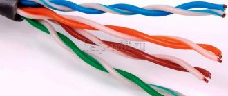
The signal from USB to the device is transmitted using twisted pairs. The core (wire) is color-coded, which simplifies the repair process.
Colored wires in the USB connector
Making the pinout is very simple: you need to mirror the desired connector and solder the wires in accordance with the color.
The main players are positive and negative contacts. Take any adapter with 5V, cut off the USB connector with a utility knife. Then you need to strip and tin the wires. For the connector, the same manipulations. Then soldering occurs according to the scheme. Each connection is wrapped with electrical tape, then they are connected to each other with hot-melt adhesive.
In USB 2.0 wiring there are only 4 shielded wires arranged linearly: two for power (first and last) and two for data transfer (second and third). They are marked as follows:
- +5V (power) is responsible for power supply.
- -D: data transfer.
- +D: Same as -D.
- GND (ground) – for grounding. Denoted by an inverted T.
USB Type A pinout
Despite the same circuits, USB types A and B have differences: In A, the arrangement of connectors is linear (from the first to the fourth), while in B, it is top and bottom:
| Top | Bottom |
| First | Third |
| Second | Fourth |
USB type B pinout
USB 3.0 has 5 additional connectors to match USB 2.0.
USB 3.0 pinout
Characteristics of 5 additional wires:
- the fifth works to receive information with a minus sign;
- the sixth is also for Data, only for +;
- seventh – grounding;
- the eighth and ninth are for data transmission (+ and -, respectively).
The USB 3.0 specification stands out among its predecessors not only in its high speed, but also in energy savings. This happens due to the function of the interrogation interface of the connected device, as well as a reduction in power in standby mode.
How to solder USB to mouse
If the mouse (keyboard) cord has come loose from the board or the plug needs to be replaced, use the tips and reference information in this article...
If the mouse (keyboard) cord has become disconnected from the board or the plug needs to be replaced, use the tips and help information in this article.
The cord is torn from the board
To solder a cord torn from a mouse or keyboard, you need to determine the purpose of the soldering points on the board and know the color coding of the wires. Often the purpose of the cord wires is written directly on the board, in the place where the wires were soldered. And the wires usually have standard markings, which will be discussed below. When encountering non-standard colors, follow the information from the relevant articles:
USB devices
In the case of USB devices, the letter designations will be: V, D-, D+, G (not necessarily in that order). There may be a point for soldering the cable braid - SG. The classic colors in a USB cord are:
V - Red D- - White D+ - Green G - Black SG - Black thick (not insulated in the cable)
In some models of USB devices you can find markings characteristic of PS/2:
V - Red D - White C - Green G - Black
In USB device cords, wire colors may differ from standard ones. Then the article “Custom USB colors in mouse and keyboard cords” can help you.
If there is no information on your device in the article, you will have to call the cord yourself. The pin assignments of the USB plug are clearly defined (see figure↓), all that remains is to find out what color each pin rings with. The figure shows an example of defining the “G” wire. With only one of the four wires, the multimeter in ohmmeter mode will show about zero ohms. This is the desired wire. This study should be repeated with other contacts.
PS/2 devices
Classic wiring of PS/2 keyboards and mice:
V - Blue D - Orange C - White G - Green
However, PS/2 keyboard cords often come in the same color scheme as USB devices:
V - Red D - White C - Green G - Black
The colors in the PS/2 device cord may not match the standard. In this case, refer to the article “Custom PS/2 Colors”.
Actions in the absence of markings
If there are no inscriptions on the board, we examine the tracks on the printed circuit board coming from the places where the cord is soldered. This study should be guided by the following features:
• The longest and widest path is usually “G”. All electrolytic capacitors are soldered to this track with their negative contact. The negative contact is marked on the capacitor body with a longitudinal strip.
• Marking the polarity of electrolytic capacitors and LEDs will tell us the positive track - “V”. It is usually shorter and thinner than "G". If there are “electrolytes” on it, then they are soldered to it with positive contacts.
• Keyboard LEDs are soldered with positive contacts to the positive track.
• The two shortest and virtually identical traces on the board are D- and D+ (D and C in the case of PS/2 devices). Without further ado, they go to the controller chip. Which of them is which is determined experimentally. With regard to these contacts, experiments are safe.
The plug is torn from the cord
If the colors in the cord are standard, then from the pictures below you will understand which wire to solder to which pin of the connector.
In the case of non-standard colors, please refer to the articles:
Or determine the purpose of each wire yourself by the markings on the board or by the tracks, as shown above.
Thank you very much for the article. I am writing to you using a mouse and keyboard that I fixed thanks to you. The information on determining V and G is very useful.
People often ask the question: “The wire has come off the keyboard, where should I solder it?” or: “The dog chewed the mouse connector. How to solder a new one?
If the wire is torn off from the device board, then look at the letter marking on the board.
For USB devices, the contacts are marked as follows: V, D-, D+, G. There may also be SG - braid.
True, there may not be any letter designations on the board. I will tell you below how to deal with this problem.
So, what color should I solder where?
SG - Black thick
This marking is typical for PS/2 devices, but oddly enough, it is also found on boards of USB devices.
If you don’t see the classic colors (Red, White, Green, Black) in the USB cable, these tables can help you:
If your device is not listed in the tables, take a multimeter in ohmmeter mode and ring the cord yourself: which contact is ringing with which wiring. The purpose of the contacts is in the picture below:
1. The longest, thickest path usually comes from contact “G”. But the V road can compete with it. It is necessary to check the electrolytic capacitors - they are soldered to the “G” track with a minus. The minus on the capacitor body is marked with a longitudinal stripe.
2. From contact “V” there is a more modest path. Electrolytes and LEDs are soldered to it with a plus.
3. Two identical tracks going straight to the controller chip are “D-” and “D+”. It is not so easy to distinguish them. We solder at random. If the device does not work, simply swap the wires on contacts D- and D+. Nothing bad will happen.
If a dog or younger sister chews off a plug from a mouse or keyboard, buy a new connector and solder it onto the cord according to the classical scheme.
If the colors in the cord stub turn out to be on the left, then either look for the pinout in the table of non-standard colors (see above) or look at the board to see which color is soldered to which contact. Above, I have already described how to calculate the purpose of a contact using a board.
If relevant, I can post similar material on PS/2 mice and keyboards.
Good luck with the renovation everyone!
Possible duplicates found
Questions? Screw your website.
@moderator, don't say thank you)
Hmm, why is it so rude? competitor, or what?