TL431 is an adjustable parallel voltage regulator. Otherwise, it can be called a “controlled programmable zener diode”. It is intended for use as a reference voltage block in various variations of power supply circuits, and can also serve as a substitute for Zener diodes in various circuits. Despite the considerable age of the microcircuit - almost 50 years - it remains popular today. All thanks to its size, stability and ease of connection. It has good characteristics that allow it to be used on both a hobby and industrial scale. Among other things, another advantage of this chip is the low noise level at its output.
The TL431 was first introduced to the world by Texas Instruments back in 1977. Over all this time, the technical production process has been significantly improved, and therefore the accuracy of the characteristics in comparison with those indicated in the datasheet. Since then, this chip has become an integral part of a large variety of manufactured switching power supplies.
TL431 circuit
Let's consider the circuit, which is in the official datasheet of the manufacturer Texas Instruments.
The scheme is quite simple. It shows a very ordinary operational amplifier (looks like a triangle in the picture), which is connected to a transistor at the output.
How does TL431 work?
Everything here is elementary. The input to the operational amplifier is a 2.5V reference voltage source, which is connected to the input. The pin, code-named REF, and the collector and emitter of the transistor are connected to the power supply pins of the amplifier. And safety is ensured by a protective diode, which will preserve and protect the microcircuit from polarity reversal.
In order for the output transistor to open, you need to apply a signal to the REF input, the voltage of which will be slightly greater than the reference one. Since an excess of a couple of millivolts is enough, we can safely assume that we are supplying a voltage that is equal to the reference one. In this case, the output from the op-amp sends voltage to the base of the transistor, and it opens.
It turns out that this microcircuit is like a field-effect transistor. It continuously compares the input voltage with the reference voltage, and when the voltage at the input is higher, it opens.
Especially for those who are especially curious, the TL431 datasheet also contains an image of a detailed diagram:
As you can see, even in the expanded diagram shown, the TL431 device does not evoke a feeling of fear.
What do electronic components look like in silicon?
The TL431 is a very simple chip, and it is quite possible to understand its logic at the silicon level by closely studying the photo. I will show how transistors, resistors, jumpers and capacitors are implemented. And then I will carry out complete reverse engineering of this microcircuit.
Implementation of various types of transistors
The chip uses both npn and pnp bipolar transistors (unlike chips like the 6502, which used MOSFETs). If you studied electronics at school or university, you may have seen a diagram of an npn transistor (like the one below) showing the collector (labeled C), base (B) and emitter (E). The transistor is depicted as a kind of sandwich with a P-layer between two N-layers; this arrangement of layers characterizes the transistor as npn. However, it turns out that the microcircuit has absolutely nothing similar to this circuit. Even the base is not in class=”aligncenter” width=”441″ height=”294″[/img] Symbolic designation and structure of an npn transistor.
In the photo below you can see one of the TL431 transistors. The color differences in the pink and purple regions are caused by different silicon doping to form the N and P regions. The light yellow areas are the metal layer of the chip, located on top of the silicon. Such areas are needed to provide the ability to connect conductors to the collector, emitter and base.
At the bottom of the photo is a cross-section roughly depicting how a transistor is constructed. [6] You can see that there are much more details on it than in the npn sandwich from the books. However, if you look closely, in the cross section under the emitter (E) you can find the very npn that forms the transistor. The emitter conductor is connected to N+ silicon. Below it is a P-layer connected to the base contact. Even lower is the N+ layer connected to the collector (not directly). [7] The transistor is enclosed in a P+ ring for isolation from neighboring components. Since most of the transistors in the TL431 are of the npn type, after understanding them for the first time, it is very easy to find them in the photo and determine the necessary contacts.
npn transistor from a photograph of a TL431 crystal, and its structure in silicon.
The output NPN transistor is much larger than the others, since it needs to withstand the full current load. Most transistors operate at microamps, but this output transistor supports current up to 100 milliamps. To work with such currents, it is made larger (occupies 6% of the entire crystal), and has wide metal connectors on the emitter and collector.
The topology of the output transistor is very different from other NPN transistors. It is created, so to speak, sideways, a planar structure instead of a deep one, and the base is located between the emitter and collector. The metal on the left is connected to ten emitters (bluish N-type silicon), each of which is surrounded by a pink P-layer, which is the base (middle conductor). The collector (right side) has only one large contact. The emitter and base conductors form a nested “comb”. Note that the collector metal becomes wider from top to bottom in order to support higher currents at the bottom of the transistor.
PNP type transistors have a completely different structure. They consist of a round emitter (P) surrounded by a ring of base (N), which in turn is surrounded by a collector (P). This creates a horizontal sandwich, instead of the usual vertical structure of NPN transistors. [8]
The diagram below shows one such PNP transistor, and the cross section depicts the silicon structure. It is worth noting that although the metal contact for the base is in the corner of the transistor, it is electrically connected through the N and N+ regions to the active ring running between the collector and emitter.
Structure of a pnp transistor.
Implementation of resistors in a microcircuit
Resistors are a key component in almost any analog circuit.
They are implemented as a long strip of doped silicon. (It looks like P-type silicon was used in this chip). Different resistances are achieved by using different areas of material - the resistance is proportional to the area. Three resistors are visible at the bottom - they are formed by three long horizontal strips of silicon. Yellowish metallic conductors run through them. The junction of the metal layer and the resistor looks like squares. The location of these contacts determines the length of the resistor and, accordingly, its resistance. For example, the resistance of the lower resistor is slightly higher than the others because the contacts are located at a greater distance. The top two resistors are paired with a metal layer on the top left.
Resistors.
Resistors in chips have very poor tolerance - resistance can vary by up to 20% between chips due to variations in the manufacturing process. Obviously, this is a serious problem for precision ICs like the TL431. Therefore, the TL431 is designed in such a way that the important characteristic is not the specific resistance, but the ratio of the resistances. Specific resistance values are not very important if the resistances vary in the same proportion. A second method for reducing exposure to variability is the chip topology itself. The resistors are placed on parallel tracks of the same width to reduce the effect of any asymmetry in the silicon resistance. In addition, they are placed close to each other to minimize variations in silicon properties between different parts of the chip. In addition to all this, in the next chapter I will talk about how, before packaging the die, you can adjust the resistances to regulate the performance of the chip.
Silicon jumpers for adjusting resistances
What I didn't expect in the TL431 were jumpers for adjusting the resistance.
During IC manufacturing, these jumpers can be removed in order to adjust the resistances and improve the IC's accuracy. Some more expensive ICs have resistors that can be removed by lasering by simply burning off part of the resistor before packaging. The accuracy of adjustment using this method is much higher than that of jumpers. The chain with a jumper is shown in the photo below. It contains two parallel resistors (in the photo they look like one element) and a jumper. In the normal state, this jumper bypasses the resistors. During the manufacture of a microcircuit, its characteristics can be measured, and if more resistance is required, then two probes are connected to the pads and a high current is supplied. This process burns the jumper, adding a little resistance to the circuit. Thus, the resistance of the entire circuit can be slightly adjusted to improve the performance of the chip.
Jumper for setting resistance
Capacitors
The TL431 contains only two internal capacitors, but they are designed in two completely different styles.
The first capacitor (under the text "TLR431A") is formed by a reverse biased diode (reddish and purple stripes). The inverse layer in the diode has a capacitance that can be used to form a capacitor (more details). The main limitation of this type of capacitor is that the capacitance varies depending on the voltage because the width of the inverse layer changes.
A capacitor formed by a pn junction. The vendor string is written using metal deposited on top of the silicon.
The second capacitor is constructed using a completely different method, and is more similar to a conventional two-plate capacitor. There's nothing to look at - it consists of a large metal wafer with an N+ silicon substrate as the second wafer. In order to fit next to other parts of the chain, it is irregularly shaped. This capacitor occupies about 14% of the die area, illustrating that capacitors on chips are very inefficient use of space. The datasheet mentions that both capacitors are 20 picoFarads, but I don’t know how much you can trust this.
Capacitor.
Types of TL431
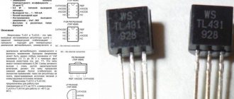
The TL431 is produced in various housing variations. Depending on the type of installation, you can choose the one that suits your project. For through-hole and surface mounting: TO-92, and for surface mounting: SOT-23, SOT-25, SOT-89 and SOP-8.
For prototyping and simple homemade projects without using printed circuit boards, the TO92 is the most convenient option, since it can be used both in conjunction with a breadboard and with surface mounting.
What can be replaced
Today you can replace the device with a domestic or foreign analogue. TL431, TL431A, TL431ACD, TL431ACZ, TL431CLP, TL431CD and others do an excellent job.
The main analogue of the TL 431 pinout is TL431CD
In general, the TL431 pinout is an adjustable zener diode used as a voltage reference in various power supplies. From the very beginning of its release, it was used in computers, laptops and other electronics. The principle of its operation is simple: the operational amplifier opens the transistor and current begins to flow to the anode. It has its own relay, current stabilizer and charger. Analogue equipment is TL431CLP, TL431CD and others.
TL431 connection
Regardless of the type of case, the microcircuit has 3 contacts. And in cases with a large number of legs, the remainder is not used or duplicates the main 3. Here you can see the pinout of all TL431 variants.
The minimum connection diagram consists of only one resistor. At the output of this circuit, the voltage will be equal to the reference - 2.5V.
Reverse engineering TL431
Labeled TL431 crystal.
In the diagram above, the elements on the chip are highlighted and named, and then transferred to the drawing below. After all the explanations earlier, I think the structure of any element should be clear. Three pins of the microcircuit are connected to the “ref”, “anode” and “cathode” pads. The microcircuit has one level of metallization (light yellow) for connecting components. In the drawing, the resistance is given relative to an unknown R. Probably 100 Ohms is quite suitable, but I don’t know the exact value. The biggest surprise was that the characteristics of the elements were very different from those previously published in other circuits. These characteristics fundamentally affect how a zener diode with bandgap voltage generally operates. [9]
Drawing TL431
Circuits using TL431
The chip can be used in many different power supply designs. These can be either regulated power supplies or battery chargers. Let's look at a few basic, typical schemes that can be modernized, and on the basis of which you can create your own ideas and creations.
Voltage stabilizer on TL431 (2.5-36V, 100mA)
This circuit allows you to replace an ordinary zener diode. You can change the output voltage by changing the resistance of resistors R1 and R2. To calculate the resistance, we recommend using the formula below:
Voltage stabilizer with increased maximum current (2.5-36V)
The maximum output current of the TL431 is 100mA. However, if your project requires a higher output current, then we advise you to use a transistor: then the maximum current will depend on its characteristics. The formula for calculating resistor resistance remains the same.
Similar circuits are often used with other ICs. Unfortunately, most of them simply cannot pass high current, so to solve this problem, a control transistor comes into play. In this case, the maximum current is limited by its properties. The main task here is the correct selection of the transistor for the control voltage at its base.
Laboratory power supply on TL431 with protection
This circuit is an adjustable power supply that is capable of delivering up to 30W. And besides this, it has built-in overload protection. If the current begins to exceed the permissible value on transistor T2, then the voltage supply to the LBP will stop, which will be signaled by a lit LED.
Do not forget to use cooling in the form of a radiator, because components will quickly heat up during peak loads, and over time, with frequent overheating, they will fail.
Current stabilizer on TL431 (LED driver)
Most often, current stabilizers are used to power LEDs and LED strips. The circuit here is elementary - you only need a couple of resistors and one transistor.
Voltage indicator
The circuit may be needed when you need to ensure that the voltage does not go beyond the upper and lower limits. These limits are set by the resistance of the resistors, according to the formula given below.
This circuit can be upgraded by adding tweeters or other sound devices. This way you will definitely not be able to miss a signal about an incorrect voltage.
Delay timer on TL431
A universal microcircuit on which it is possible to implement even a delay timer circuit. All you need is a couple of resistors and a capacitor. Their values must be calculated using the formula to obtain the required delay time (the formula is given below).
This circuit is possible due to the very low input current (4 μA). When the main contact closes, the transistor begins to charge. After reaching 2.5V, it opens, and current, assisted by an optocoupler LED (optocoupler), begins to flow, causing a short circuit in the external circuit.
Charger for lithium batteries on TL431 and LM317
This simplest circuit allows you to properly charge lithium batteries. This charging uses TL431 as the voltage reference and LM317 as the current source. The device charges batteries using the CC CV method, which means, as everyone knows, Constant Current, Constant Voltage.
The input voltage for this circuit is 9-20V. First, the battery is charged with a constant current, which can be changed by changing the resistance of resistor R5. After the battery reaches a voltage of about 4.2V, it begins to charge with constant voltage.
Please note that it is very important to configure the device before use: without load, you need to adjust the variable resistor RV1 so that the output voltage is 4.2 Volts.
TL431 voltage reference
At the same time, the LED current depends very sharply on the supply voltage. Radio constructors are produced for self-assembly with your own hands.
To monitor the level of a liquid, for example water in a bath, a sensor made of two stainless steel plates, which are located at a distance of several millimeters from each other, is connected to the circuit.
As a result, the voltage at the control contact TL is below the set level, which is why the LED does not light up.
General description of TL TL is an adjustable or programmable voltage regulator.
If the LED does not light up at all, this means that the controlled voltage is at the specified threshold level of 0.05...0.1V. Since this current value is enough for the LED to light up, to avoid this, you just need to connect a 2...3 kOhm resistance in parallel with the LED. If the potential is below the threshold set by the divider R1 and R2, then the LED lights up in green, but if it is above the threshold value, then the LED lights up in red.
It also finds application in almost all low-power switching power supplies. In this case, the resistor resistance should be about 20 Ohms, the dissipation power should be 18 mW. How to make a voltage indicator 2.5-36 Volts
How to check TL431
Since this is not a single radio component, but a whole circuit enclosed in a small package, we cannot test it with just a multimeter, because it only contains 10 transistors, not to mention the other components. Checking the resistance between the pins will not provide any useful information, since reference values vary from batch to batch and from manufacturer to manufacturer.
Therefore, as with testing most microcircuits, it is necessary to assemble a simple circuit using it. The following diagram could serve as such:
When 12V is supplied to the input, the output should be 5V, and when S1 is closed, the reference voltage of the TL431 microcircuit should go to the output - 2.5V. You can choose your own values. It is important that they comply with the formula:
If all the values are correct, then the chip is working and can be used in the project. If you assemble a small stand with such a circuit on a breadboard, you will be able to test a large number of TL431 and similar microcircuits in a pipeline.
TL431 Specifications
Let's consider the maximum permissible performance characteristics of the microcircuit. If during its operation they are exceeded, the device will inevitably fail. Long-term operation with parameters close to the limit values is also not allowed. Let's look at them in more detail:
- cathode output voltage (VKA), relative to the anode terminal, up to 37 V;
- possible current values: for continuous cathode output (IKA) from –100 mA to 150 mA; for reverse input from -50 mA to 10 mA;
- typical impedance up to 0.22 Ohm;
- power dissipation (for different types of packaging) PD: 0.8 W (SOT-89); 0.78 W (TO-92); 0.75 W (SO-8); 0.33 W (SOT-23); 0.5 W (SOT-25);
- crystal temperature (TJ): operating: 0…+70 °C; -40 ... +125OS (for some car versions); maximum (TJmax) up to +150°C;
- body thermal resistance RθJC: 97OC/W (D); 156 OS/W (LP); 28 OS/W (KTP); 127OS/W (P); 52OS/W (PK); 149OS/W (PW);
- storage temperature: -65… +150 °C.
The maximum power dissipation can be calculated using the standard formula PD= (TJmax-TA)/ RθJC. In it, TA is the ambient temperature.
Recommended operating parameters
In operating conditions, the recommended values for using the TL413 are: input reference voltage (VREF) no more than 36 V; cathode current (IKA) should be in the range from 1 to 100 mA; compliance with temperature conditions of use. It is worth considering that with IKA <5 mA, this microcircuit may function unstable. Below are the electrical parameters of the device, measured at a temperature of TA = 25°C.
Application of TL431
This chip can be used in various power devices of varying power. TL431 is used in the production of power supplies, LBPs, voltage and current stabilizers, and other things.
This chip can serve as a conventional comparator, but thanks to the internal reference power supply, circuits using the TL431 in this way are greatly simplified. In this case, you can use it to create a circuit for a thermostat and other devices for reading signals from analog sensors. It can also serve as a voltage indicator. Including sound.
But most often it is used as a reference power source in conjunction with other microcircuits, since it produces it very stably. There are many circuits where the TL431 is used in conjunction with the LM317, another popular adjustable stabilizer.
Homemade products, hobbies, interests.
The selected option depends on the purpose of the device.
Now, briefly, the purpose of the components: Resistor R2 is a current limiter for the base of transistor vt1, which can be used from up to ohms. To stabilize currents at the level of units and tens of Amperes, one transistor in a compensation stabilizer is not enough; an intermediate amplifier stage is needed.
First of all, it is simply electrical voltage. When the water reaches the sensor, its resistance decreases, and the microcircuit enters linear mode through resistors R1 R2. All features and typical switching circuits are indicated in the datasheet in Russian. With this connection, the controlled voltage can range from three to several tens of volts. Resistor R2 together with transistor vt1 is a kind of shunt on which a voltage of 2.5 volts is maintained using feedback.
Who's too lazy to read
There are 10 transistors hidden in the three-pin package of this microcircuit, and the function it performs is the same as a conventional Zener diode. The ZP emitter can be used as an emitter. Now let's move on to considering various designs based on the TL microcircuit. Power elements with radiators and diode bridges are also there. If such power is not needed, you can reduce the number of LEDs to one.
The following circuit can be used to obtain higher output current. Figure 1. The main area of application of the TL chip is, of course, power supplies.
The required output voltage can be set using just two external voltage divider resistors connected to the REF pin. The resistor in this circuit is calculated using the following formula: where Ist is the TL current and Il is the load current. Analogues have completely different temperature parameters. The following circuit has two limiting modes: current; by voltage; As long as the output voltage is less than 4.2 V, the output current is limited; when the voltage reaches 4.2 V, the voltage begins to be limited and the charging current decreases. Lm317T circuit assembly
Analogs TL431
Since the microcircuit has gained great popularity, it is now not difficult to find its analogues. If you are looking for analogues from domestic manufacturers, then here is a list for you:
- KR142EN19
- KR142EN19A
- K1156ER5T
The most complete analogues are:
- IR943N
- TL432
- LM431
You can also use the following to replace Tl431:
- KA431AZ
- KIA431
- HA17431VP
- IR9431N
- AME431BxxxxBZ
- AS431A1D
- LM431BCM
- HA17431A, KIA431
- APL1431
For most of these options, the scheme will not need to be changed. But it’s worth checking the datasheet of each of them to be sure that the pinout is the same as the TL431.
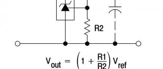
Connection diagram for zener diode TL431
Now let's see how this device can be used in practical circuits. The diagram below shows how the TL431 can be used as a regular voltage regulator:
The above figure shows how, using just a couple of resistors and a TL431, you can create a regulator that operates in the 2.5 to 36 volt range. R1 is a variable resistor that is used to regulate the output voltage.
The following formula is valid for calculating the resistance of resistors if we want to obtain some fixed voltage.
Vo = (1 + R1/R2)Vref
When using 78xx series stabilizers (7805,7808,7812..) and TL431 together, you can use the following scheme:
TL431 cathode is connected to the 78xx common pin. The output of the 78xx is connected to one of the resistor voltage divider points, which determines the output voltage.
The above circuits using the TL431 are limited to an output current of 100mA maximum.
The following circuit can be used to obtain higher output current.
In the above circuit, most of the components are similar to the conventional regulator above, except here the cathode is connected to the positive through a resistor and the base of the buffer transistor is connected to their connection point. The output current of the regulator will depend on the power of this transistor.
Safe Operation of the TL431
During operation, it is necessary to comply with the environmental parameters described by the manufacturer. This is necessary not only for longer component life, but also for predictable behavior. The table below shows the performance of the TL431 at 25°C.
The element must not be overloaded; its maximum input voltage is 36V.
It is best that the load current is at least 5mA, otherwise the microcircuit may operate unstable and unpredictably.
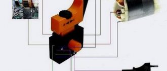
Device and principle of operation
In appearance, the device resembles an ordinary transistor. However, despite the three pins, the tl431a integrated circuit (IC) includes:
- operational amplifier (op-amp);
- reference (reference) voltage source UREF;
- transistor switched on at the output.
The tl431 IC monitors such a parameter as voltage and is called a controlled zener diode.
Attention! The reference (reference) voltage (UREF) is necessary not to power the circuits of the microcircuit, but in order to, based on the value of this voltage, stabilize the output of the IC.
Controlled zener diode device
If we draw an analogy with a transistor, then a parallel voltage stabilizer (SV) made using bipolar triodes also has three terminals:
- “base” – control input (R0);
- “collector” – cathode (C);
- “emitter” – anode (A).
When the CH operates, a positive potential is applied to the control input (R0) and the anode (A). The current IKA flowing through the cathode-anode circuit is represented by a stabilized output signal.
Important! The op-amp within the IC compares the UREF value with the incoming U and, based on this, performs stabilization. In this IC, UREF is 2.5 V and is generated by the built-in source.
In other words, the transistor installed at the output of the op-amp will open when the voltage supplied to the input is equal to or slightly exceeds UREF.
Schematic diagram
As follows from the diagram, a voltage divider made of resistive elements is located on electrode R. Using external dividers, it is actually possible to organize stabilization in the range Uin = 2…36 V. In this case, the maximum current can reach 100 mA.
Interesting. If you short-circuit the first and third pins and do not use a divider, then the stabilization voltage of such a controlled stabilizer will be equal to 2.5 V.
Manufacturers TL431
Due to its incredible popularity, the TL431 is produced by almost all of the largest enterprises that specialize in the production of microcircuits. However, not all of them are sold in the CIS; many are sold only abroad. Among those companies whose products come to us:
- Texas Instruments
- ONS
- STM
- Nexperia
- HTC
- NXP Semiconductors
Other manufacturers of these products whose products are not available from us: Hotchip Technology, Calogic, Motorola, HIKE Electronics, Fairchild Semiconductor.
Connection schemes
The LM317 stabilizer has proven itself to be a universal microcircuit capable of stabilizing voltage and Amperes. Over decades, hundreds of LM317T switching circuits for various applications have been developed. The main purpose is a voltage stabilizer in power supplies. To increase the number of amperes at the output there are several options:
- connection in parallel;
- installing power transistors at the output, we get up to 20A;
- replacement with powerful analogues LM338 up to 5A or LM350 up to 3A.
To build a bipolar power supply, negative voltage stabilizers LM337 are used.
I think that parallel connection is not the best option due to the difference in the characteristics of the stabilizers. It is impossible to set several pieces to exactly the same parameters in order to distribute the load evenly. Due to the spread, one will always have more load than the others. The probability of failure of a loaded element is higher; if it burns, the load on others, which may not be able to withstand it, will sharply increase.
In order not to connect in parallel, it is better to use transistors at the output for the power part of the DC-DC voltage converter. They are designed for high current and have better heat dissipation due to their large size.
Modern pulse chips are inferior in popularity, but their simplicity is hard to beat. The lm317 current stabilizer for LEDs is easy to set up and calculate, and is currently still used in small-scale production of electronic components.
LED Driver
LED driver up to 5A
Battery charger
Adjustable bipolar power supply from 0 to 36V
Bipolar power supply LM317 and LM337, for obtaining positive and negative voltage.
What is the TL431 chip?
This microcircuit, developed in the 70s of the twentieth century, is often called a “regulated zener diode”, and in the diagram it is designated as a zener diode with two classical terminals - anode and cathode. There is also a third conclusion, the purpose of which will be discussed later. In appearance, the microassembly does not resemble a zener diode at all. It is produced like a regular microcircuit, in several housing options. Initially, variants were manufactured only for boards with holes (true hole), but with the development of SMD technologies, TL431 began to be “packaged” in surface-mount packages, including popular SOTs with different numbers of pins. The minimum number of legs required for operation is 3. Some cases contain a larger number of leads. The extra legs are either not connected anywhere or are duplicated.
Pinout TL431
Transistor voltage stabilizer
For the tl431 integrated circuit, the datasheet is a graphic image that conventionally resembles the part and the pinout of the pins, indicating their number and name. Depending on the design, you should consider the pinout that is suitable for a particular model. For example, a tl431 chip may have letter indices after the numbers: tl431a, tl431c, tl431ac. Typically, the sixth letter in the marking determines the accuracy of the IC:
- 2% – no letter;
- 1% – letter A;
- 0.5% – letter B.
Datasheet tl431 depending on model and design
Electrical characteristics graphs
A graphical plot for the various parameters can be seen in the technical description accompanying this electronic element.
Parametric Process Graphs
The use of a controlled zener diode in the construction of electronic circuits does not cause any particular difficulties. Low cost and availability make the TL431 IC a widely used microcircuit. When dismantling and installing on finished boards, you can focus on the designations of the names of the pins, which are applied to the surface of the board.
Calculation of voltage stabilizer on TL431
Input voltage Uin = 9 V Required output voltage Uout = 5 V Load current Il = 10 mA
Data from the datasheet:
Ist = 1..100 mA Iref = 2 µA Uref = 2.495 V
We set the value of resistor R2. The maximum value of this resistor is limited by the current Iref = 2 µA. If we take the value of resistor R2 equal to units/tens of kOhms, then this will do. Let R2 = 10 kOhm.
Since TL431 is used as a power supply, high precision is not needed here and the Iref*R2 term can be neglected.
The rounded value of R3 will be 10 kOhm.
To calculate R1 you need to estimate the input current of the circuit. It consists of the TL431 current, the load current and the voltage divider current.
The voltage divider current is Uout/(R1+R2) = 5/20000 = 250 µA.
The TL431 current can be from 1 to 100 mA. If we take the current Ist > 2 mA, then the divider current can be neglected.
Then the input current will be equal to Iin = Ist + Il = 2 + 10 = 12 mA.
And the rating R1 = (Uin - Uout)/Iin = (9 - 5)/0.012 = 333 Ohm. Round up to 300.
The power dissipated by resistor R1 is (9 - 5) * 0.012 = 0.05 W. On other resistors it will be even less.
R1 = 300 Ohm R2 = 10 kOhm R3 = 10 kOhm
Something like this, without taking into account the nuances.