Theorists
First, let's define the purpose of this part, as well as the basic concepts and terms associated with it.
What is an inductor
Variety of reel sizes
An inductor is a radio element used in various circuits for the following:
- Beat smoothing;
- Interference suppression;
- AC current limitation;
- Energy storage and more.
This element is a spiral, screw or helical coil made of an insulated conductor. The part has a relatively small capacitance and low active resistance, while it has high inductance, that is, the ability to generate EMF (electromotive force) in the conductor when electric current flows in the circuit.
Chokes on a printed circuit board
- The inductor, depending on the place and purpose of application, may have other names. For example, if an element is used for high-frequency isolation in different parts of the circuit, storing the energy of the magnetic field of the core, smoothing out ripples and suppressing interference, the coil is called a choke or a reactor (the second name is rarely used).
- If we talk about power electrical engineering, then the name rector has been established - it is used when it is necessary to limit the current, for example, if there is a short circuit on a power line.
Solenoid
- There are also cylindrical inductors called solenoids. The length of such a cylinder is several times greater than its diameter.
Interesting to know! The magnetic field inside the solenoid is uniform. This magnetic field can perform mechanical work by drawing in the ferrite core.
Coil from the solenoid relay on the starter
- Inductors are also used in electromagnetic relays, where they are called relay windings.
- Similar elements are also installed in induction heaters - here they are called heating inductors.
Diagram of a superconducting inductive storage device
- You can also hear terms like induction storage or storage choke when talking about pulsed voltage stabilization devices.
Design features
The structure of the inductor
Structurally, the inductor is an insulated single-core or stranded conductor (usually varnished copper wire) wound in a spiral or screw around a dielectric core (frame). The core shape can be round, toroidal, rectangular, square. The materials used for the core have a magnetic permeability higher than that of air, which additionally retains the magnetic field near the coil, which means the inductance increases.
There are also coils that do not have a core at all, or it is adjustable, which allows you to change the inductance of the part.
Toroidal coil
The winding of the conductor can be single-layer, it is also called ordinary with a step, or multi-layer (the names universal, pile-on, ordinary are used). The distance between the turns is called the pitch.
Interesting to know! The winding pitch can be progressive, that is, its value varies along the length of the coil. This winding is used to reduce the “parasitic” capacitance.
Application
Coils are used in signal processing and analog circuits. When combined with capacitors and other radio components, they can form sections of circuitry that amplify or filter certain signals.
Chokes are widely used in power supplies, where they, together with filter capacitors, are designed to eliminate residual noise and other fluctuations that occur at the output.
Transformer structure
If two coils are connected by one magnetic field, you get a transformer - a device capable of transmitting electricity from one part of the circuit to another, due to electromagnetic induction, simultaneously changing the voltage value.
For reference! Transformers are capable of operating only with alternating current.
Main characteristics of inductors
Before we understand how current behaves when passing through an inductor in a circuit, let's first find out the main characteristics of this element.
Definition of inductance: formula
- First of all, we are interested in inductance - a value expressed numerically by the ratio of the magnetic field flux, which is created by the flowing current, to the strength of this current itself. This parameter is measured in Henry (H).
- In simpler terms, this phenomenon can be described as follows. When current flows through the inductor, an electromagnetic field is created, which is directly related to the emf, which counteracts the change in alternating voltage, that is, a current appears in the circuit that flows in the opposite direction to the main one.
- Measuring the current strength on the inductor and alternating voltage resist this force, or rather the opposite. This property of the element is called inductive reactance, which is in antiphase to the capacitive reactance of a capacitor connected to an alternating current circuit.
Advice! The change in the inductance of the coil occurs in proportion to the change in the number of turns.
Calculation of coil magnetic field energy
- It has long been known that any magnetic field has some energy. It follows that the magnetic field of the coil also has a certain supply of magnetic energy. The value of this reserve is equal to the energy expended to ensure the flow of current (I) in opposition to the EMF. Calculations are made using the above formula.
Hydro turbine
- To make it even clearer, let's compare a coil with a hydraulic turbine. So, the water flow that is directed through the turbine will feel its resistance until the turbine spins up completely. It has some inertia, which means it will rotate synchronously with the flow of water, without providing practically any resistance to it.
- If you try to stop the flow of water or change its direction, you will see that the turbine will continue to rotate by inertia, forcing the water to move in the same direction. The higher the inertia of the turbine, the more it will resist changing the direction of water flow.
- Exactly the same thing happens in an inductor when alternating current begins to flow in the opposite direction.
When coils are connected in series, their inductance adds up
- The influence of current on the inductance of the coil is expressed not only in the form of the main interaction effect. Parasitic effects are often observed, due to which the alternating current resistance of the inductor cannot be called purely reactive. Due to these effects, some losses occur in the coil, which are measured as loss resistance. This value is the sum of losses in the core, wire, screen and dielectric.
- Each loss is caused by different reasons. There are three of them in the wires: they have, although small, but still active ohmic resistance; this resistance increases with increasing frequency, which is due to a decrease in the amplitude of electromagnetic waves as they penetrate deep into the conducting medium (this phenomenon is called the skin effect) - in other words, the current is displaced to the upper layers of the wire, due to which the area of the conductor changes , and therefore its resistance; if the wires are twisted into a spiral, a proximity effect occurs, due to which the active cross-section of the conductor and the overall resistance also change.
Welding machine choke
- Losses in the dielectric may arise due to the interturn capacitor, or due to its electromagnetic properties. However, in fairness, it is worth noting that the losses in this part of the part are so small that they are often neglected in calculations.
- Losses on the core consist of two quantities: losses due to magnetization reversal of the ferromagnet (losses due to hysteresis) and losses due to eddy currents. The alternating magnetic field arising from the current flowing in the conductor induces eddy EMF in neighboring conductors - the core, the wires of the nearest turns, and even the screen. The resulting currents, which have a name in addition to eddy currents, Foucault currents, also cause losses due to the active resistance of the wire.
- Another characteristic called quality factor is also associated with resistance losses. Its value is the ratio of the reactive and active resistance of the inductor.
Parasitic inductor capacitance
- The next parameter is parasitic capacitance. The phenomenon is that some unwanted capacitive coupling occurs between the turns of the coil.
- TCI (temperature coefficient of inductance) - we all know that when heated, substances increase in size. When this happens to the coil, we get inductance instability due to changes in the length and diameter of the conductor, the length and diameter of the frame, and therefore changes in the diameter and pitch of the turns. In addition, a change in temperature affects the dielectric constant of the frame material, which entails a change in the capacitance of the coil and affects the permeability of the ferromagnetic core by the magnetic field.
- TKD (temperature coefficient of fractionation) - everything is clear here! This is a change in quality factor parameters depending on temperature.
Coil device
The coil is made by winding insulated wire around a cylindrical or toroidal frame. Insulation is a mandatory attribute; without it, due to interturn short circuit, the coil will turn into an ordinary conductor.
Contacts are installed at the ends of the wound wire. With their help, the induction coil is connected to the circuit in series with the load. A metal core can be placed inside the frame.
When making a coil, the wire is wound in two ways:
- in one layer : such a winding is called “ordinary with a step”;
- in several layers : the method is denoted by the terms “bulk” or “station wagon”.
The distance by which the turns of the wire are spaced from each other is called the pitch. When winding some coils, the pitch is gradually increased (progressive pitch), thereby reducing the parasitic capacitance.
Connecting an inductor in a circuit with direct and alternating current
In general, we have determined what an inductor is, what it is needed for, and what characteristics are important for calculating its parameters, but it is still probably not clear to the inexperienced reader how the parameters of the current flowing through this part will change.
DC powered circuit
Inductor in a DC circuit
To simplify the presentation, we will conduct a very simple experiment:
- To begin with, we need a power supply capable of producing a stable 12 volt output voltage, a 12 volt incandescent light bulb to create resistance, as well as the inductor itself.
Ferrite rod
- We will assemble the coil with our own hands from a piece of varnished copper wire and a ferrite rod.
Making an inductor
- The instructions are extremely simple - take the wire and wind it around the rod, then trim the ends with a knife so that you can connect the terminals from the power supply and solder the wires.
- The price of such a scheme is minimal, so you can easily repeat the experiment if you wish at home.
Measuring the inductance of the assembled coil
- Using an LC meter, we measure the inductance of the resulting part. As can be seen from the photo above, in the example under consideration it was 132 μH.
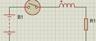
Circuit with inductor turned on
- Now we take all our parts and connect them according to the above diagram.
The circuit is included in the network
- Here's what happened in practice. As you can see, direct current flows through the coil almost unhindered, if you do not take into account the natural resistance of the conductor, because the current does not change its direction to the opposite.
In this diagram, the light bulb is replaced by a resistor, but this is not important
- Does this mean that the inductor is not applicable in DC circuits? Not at all! Here is another circuit, in which, as we see, a certain switch is already included that can open the circuit. It is at the moment of closure that the most interesting things happen.
- Since before this the current was zero, it will begin to change and grow, which will cause the magnetic field of the coil to change, which in turn will lead to the occurrence of an EMF. An induction current will appear in the coil, which will flow in the opposite direction of the main flow from the power source.
- It is at the moment of switching on that the EMF value will be maximum, since the rate of change of current at this moment is the highest, which means that the inductor current is zero.
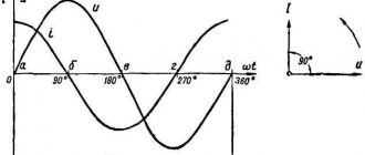
- What happens next? And then we will see that the current in the inductor will begin to increase, while the EMF, on the contrary, will decrease. Here's what it looks like on a graph.
Uin – input supply voltage; Il - change in current value; Ul – coil voltage
- The top graph shows the change in input network voltage immediately after switching on. As you can see, a constant value instantly appears.
- The following shows how the amount of current flowing through the coil changes. It also reaches a constant value, but not immediately, but after some time.
- The voltage on the coil (lower graph) also increases instantly, but immediately begins to fall. Please note that the current and voltage graphs are mirror opposites.
- If we transfer all this to our experience with a lamp, we will see that after connecting the circuit through a switch, it will not light up immediately, but with some delay.
A similar situation will occur when the circuit opens.
Physical processes in the coil when the circuit is opened
The graphs show the opposite situation, meaning that the light will continue to burn for some time after the circuit is opened.
The fact is that when the power supply is stopped, an EMF will arise in the coil again, but the induction current will now flow in the same direction as from the power source, that is, the stored energy in the coil will support the power of the circuit.
Inductive reactance
From the expressions it follows that the maximum value of voltage and the equal maximum value of e. d.s.
U
m =
EL
m=
L
ω
I
M
Dividing the written expressions by √2, we obtain the effective values of voltage and e. d.s.
U
=
EL
=
L
ω
I
whence the effective value of the current I
=
U
: ω
L
=
U
:
x
L
The value determined by the ratio of voltage to current in the circuit:
U
:
I
=ω
L
= 2π
fL
=
x
L
called inductive reactance or simply inductive reactance.
Inductive reactance is proportional to the inductance and frequency of the alternating current. When the frequency changes from f
= 0 (direct current) to
f =
∞ it changes from
x
L = 0 to
xL
= ∞.
Marking
To indicate the rating of the inductor, letter or color markings are used. There are two types of letter markings.
- Designation in microhenry.
- Designation by a set of letters and numbers. The letter r is used instead of a decimal point, the letter at the end of the designation indicates the tolerance: D = ±0.3 nH; J = ±5%; K = ±10%; M = ±20%.
The color markings can be recognized in a similar way to those on resistors. Use the table to decipher the colored stripes or rings on the element. The first ring is sometimes made wider than the others.
This is where we finish considering what an inductor is, what it consists of and why it is needed. Finally, we recommend watching a useful video on the topic of the article:
Influence of the number of turns and winding method
An inductor is a spiral made of conductive material. The operating parameters of the products will depend on the design features. Inductance is increased:
- a large number of turns per unit length;
- enlargement of the cross section;
- installation in the central part of the core with ferromagnetic characteristics.
What does the inductance of the coil depend on, examples of typical solutions
Single-turn inductance and coil inductance
To calculate an elementary structure, the converted first formula is suitable:
Ф = L * I.
If a coil is considered, this expression is transformed into the total expression of the magnetic fluxes (Ψ) generated by the individual turns:
Ψ = n * F.
The same way:
Ln = L1 * n.
In fact, for accurate calculations, differences in force lines in the central part and at the edges of the structure are taken into account. More complex expressions are used for correction.
Solenoid inductance
A sufficiently long electric coil forms parallel lines of force inside. To create a uniform distribution of energy, it is necessary to use a conductor with a thickness much smaller compared to the cross-sectional diameter. Of course, it is necessary to set the same distance between the individual turns.
This design is called a solenoid. The magnetic flux density (B) in the central working part will depend in direct proportion to the length (l) and the following parameters:
- number of turns (N);
- current (i);
- winding density (n – number of circuits per unit length);
- cross-sectional area (S);
- volume (V = S * l).
Below are the basic formulas for calculations in the absence of a core, taking into account the magnetic constant (m ≈ 1.257 * 10-6 H/m):
- B = m0 * N * (i/l) = m0 * n * I;
- Ψ = m0 * N2 * (I * S/l) = m0 * n2 * i *V;
- L = m0 * N2 * (S/l) = m0 * n2 * V.
Inductance of a toroidal coil (ring-core coil)
To calculate the induction of a coil with a core, a correction factor “m” is added to the above formulas. Taking into account the special shape of the product, the following changes must be made:
L = N2 * ((m0 * m * S)/2π * rL), or L = N2 * ((m0 * m * h)/2π) * ln(R/r),
Where:
- 2π * rL – length of the working element with an average radius rL;
- R (r) and h are the outer (inner) radius and height of the torus, respectively.
The coefficient “m” takes into account the relative magnetic permeability of a certain material to the value for a neutral environment (vacuum). If m is much greater than unity, it is possible to ignore the field distortions created by a thick conductor.
Inductance - conductor
The inductance of conductors b depends on their shape and size.
The inductance of a conductor in a given environment is determined solely by its size and shape. The inductance of a straight wire is small. The inductance of the same wire in the form of a coil is much greater. With the same coil sizes (lengths and diameters), their inductance is proportional to the square of the number of turns. The inductance of the coil is directly proportional to the magnetic permeability ia of the core.
The inductance of a conductor depends on its shape, size, and also on the properties of the environment. If the current strength changes over time, then the magnetic flux coupled to the circuit also changes. A change in magnetic flux, in turn, causes an induction current to appear in the conductor. Since the induced current is caused by a change in the current strength in the conductor itself, this phenomenon of the occurrence of induced current is called self-induction, and the resulting emf is called self-induction emf. Self-induction is a special case of the phenomenon of electromagnetic induction.
The inductance of a conductor in a given environment is determined solely by its size and shape. The inductance of a straight wire is small. The inductance of the same wire in the form of a coil is much greater. With the same coil sizes (lengths and diameters), their inductance is proportional to the square of the number of turns. The inductance of the coil is directly proportional to the magnetic permeability ia of the core.
The inductance of a conductor is numerically equal to the magnetic flux created by a current of 1 ampere flowing through a given conductor.
The inductance of a conductor characterizes its size and shape, as well as the magnetic permeability of the medium surrounding the conductor. The inductance of a conductor remains constant if its shape, size and magnetic permeability of its environment do not change.
The inductance of conductors appears only when a current that changes over time passes through them. In this work, the inductance is determined by the AC bridge method.
The inductance of the conductor L is also called the self-inductance coefficient.
The inductance of conductors I depends on their shape and size.
The inductance L of a conductor is determined by its shape, size, relative position of its individual parts, and the environment in which the magnetic flux is closed.
The inductance of conductors L depends on their shape and size.
| Proximity effect. |
The inductance of a conductor of a finite cross-section consists of external and inductance.
| Parameters of a conductor 100 mm long. |
If the inductance of the conductor connecting the screen to the chassis (case) is high, then the screen may not reduce, but increase the capacitive parasitic coupling.
Connection of coils in the presence of mutual influence of their magnetic fields.
If the coils connected in series are located close to each other, i.e., so that part of the magnetic flux of one coil penetrates the turns of the other, i.e., there is an inductive coupling between the coils (Figure 3a), then to determine their total inductance the above formula will no longer be applicable. With this arrangement of coils, there can be two cases, namely:
- The magnetic fluxes of both coils have the same directions
- The magnetic fluxes of both coils are directed towards each other
One or the other case will occur depending on the direction of the turns of the coil windings and the directions of the currents in them.
Figure 3. Connection of inductors: a) the total inductance increases due to mutual induction b) the total inductance decreases due to mutual induction.
If both coils are wound in the same direction and the currents flow in them in the same direction, then this will correspond to the first case; if the currents flow in opposite directions (Figure 3b), then the second case will occur.
Let's look at the first case, when the magnetic fluxes are directed in one direction. Obviously, under these conditions, the turns of each coil will be penetrated by its own flux and part of the flux of the other coil, i.e., the magnetic fluxes in both coils will be greater compared to the case when there is no inductive coupling between the coils. An increase in the magnetic flux passing through the turns of a particular coil is equivalent to an increase in its inductance. Therefore, the total inductance of the circuit in the case under consideration will be greater than the sum of the inductances of the individual coils that make up the circuit.
Reasoning in the same way, we will come to the conclusion that for the second case, when the fluxes are directed towards each other, the total inductance of the circuit will be less than the sum of the inductances of the individual coils.
Calculation of the inductance value of a circuit composed of two inductors L1 and L2 connected in series with an inductive coupling between them is carried out using the formula:
In the first case, the + (plus) sign is used, and in the second case, the – (minus) sign.
The value M, called the mutual inductance coefficient, is the additional inductance due to the part of the magnetic flux common to both coils.
The design of variometers is based on the phenomenon of mutual induction. The variometer consists of two coils, the total inductance of which can, if desired, be varied smoothly within certain limits. In radio engineering, variometers are used to tune the oscillatory circuits of receivers and transmitters.
What is inductance
What is inductance? It is a physical quantity that tells us about the magnetic properties of an electrical circuit. Inductance is measured in H (Henry).
If you don’t understand what we’re talking about at all, then I advise you to read this article first.
In electrical circuits, for example, we come across some strange coils, chokes, and many do not even know their functional role. In this article I will try to explain in an accessible language what inductance is and how to apply this phenomenon at your favorite job.
Let's look at the picture
Let's start moving the conductor in a magnetic field in such a way that it crosses the field lines of a permanent magnet. If this condition is met, then an electromotive force (EMF) appears in our conductor. Or vice versa, the conductor remains in place, and the magnet is moved so that the magnet's force lines intersect the conductor. Now there was an example of electromagnetic induction. The value of the induced electromotive force in a conductor is directly proportional to the magnetic induction of the field, the speed of movement and the length of the conductor
The direction of the generated electromotive force in the conductor is determined through the right-hand rule.
The right hand is in such a position that the magnetic force lines enter the palm. Consequently, the thumb shows us the direction of movement of the conductor, and the other fingers will show us the direction of the generated electromotive force.
To enhance the electromotive force of induction, electric coils are used
And if you apply voltage to the coil, then a current will flow through its turns, which creates its own magnetic field.
Theoretical background
If a current flows in a conducting circuit, the current creates a magnetic field.
We will consider in a quasi-static approximation, implying that the alternating electric fields are weak enough or change slowly enough so that the magnetic fields generated by them can be neglected.
We consider the current to be the same along the entire length of the circuit (neglecting the capacitance of the conductor, which allows charges to accumulate in different parts of it, which would cause uneven current along the conductor and would significantly complicate the picture).
According to the Biot-Savart-Laplace law, the magnitude of the magnetic induction vector created by some elementary (in the sense of the geometric smallness of the conductor section considered as an elementary source of the magnetic field) current at each point in space is proportional to this current. Summing up the fields created by each elementary section, we come to the conclusion that the magnetic field (magnetic induction vector) created by the entire conductor is also proportional to the generating current.
The reasoning above is true for vacuum. In the case of the presence of a magnetic medium (magnet) with a noticeable (or even large) magnetic susceptibility, the magnetic induction vector (which is included in the expression for the magnetic flux) will differ noticeably (or even many times) from what it would be in the absence magnetic (in vacuum). We will limit ourselves here to a linear approximation, then the magnetic induction vector, although perhaps increased (or decreased) by a noticeable number of times compared to the absence of a magnet with the same circuit with current, nevertheless remains proportional to the current generating it.
Then the magnetic flux, that is, the field flux of the magnetic induction vector:
Φ=∫SB⋅dS{\displaystyle \Phi =\int \limits _{S}\mathbf {B} \cdot \mathbf {dS} }
through any specific fixed surface S
(in particular, through the surface of interest to us, the edge of which is our contour with the current) will be proportional to the current, since it is proportional to the current
B
everywhere under the integral.
Note that a surface whose edge is a contour can be quite complex if the contour itself is complex. Even for a circuit in the form of a simple multi-turn coil, such a surface turns out to be quite complex. In practice, this leads to the use of some simplifying representations that make it easier to represent such a surface and approximately calculate the flow through it (and in connection with this, some additional special concepts are introduced, described in detail in a separate paragraph below). However, here, with a purely theoretical consideration, there is no need to introduce any additional simplifying concepts; it is enough to simply note that no matter how complex the circuit is, in this section we mean the “full flow” - that is, the flow through the entire complex (as would be a multi-leaf) surface stretched over all the turns of the coil (if we are talking about a coil), that is, what is called flux linkage. But since we don’t need to specifically calculate it here, but only need to know that it is proportional to the current, we are not too interested in the specific type of surface through which we are interested in the flow (after all, the property of proportionality to the current is preserved for any
).
So, we justified:
Φ {\displaystyle \Phi \ }~ I,{\displaystyle \I,}
this is enough to state by introducing the notation L
for the proportionality coefficient, that
Φ=LI.{\displaystyle \Phi =LI.}
In conclusion of the theoretical justification, we will show that the reasoning is correct in the sense that the magnetic flux does not depend on the specific shape of the surface stretched over the contour. (Indeed, even the simplest contour can be stretched - in the sense that the contour must be its edge - not a single surface, but different ones, for example, starting with two coinciding surfaces, then one surface can be bent a little, and it will no longer coincide with second). Therefore, it is necessary to show that the magnetic flux is the same for any surfaces stretched over the same contour.
But this is really true: let’s take two such surfaces. Together they will form one closed surface. And we know (from Gauss’s law for the magnetic field) that the magnetic flux through any closed surface is zero. This (taking into account the signs) means that the flux through one surface and the other surface are equal. Which proves the correctness of the definition.