Hello everyone, we continue to study electronics from the very basics, and the topic of today's article will be inductor . Looking ahead, I will say that first we will discuss theoretical aspects, and several future articles will be devoted entirely to consideration of various electrical circuits that use inductors, as well as elements that we studied earlier in our course - resistors and capacitors.
CONTENT
Depending on the purpose of the inductor, there are:
- loop coils (together with capacitors forming an oscillatory circuit);
— communication coils (transmitting high-frequency oscillations from one circuit to another);
- high-frequency chokes (inductors that block the path of high-frequency currents).
[/td]
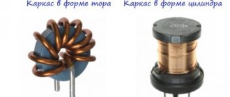
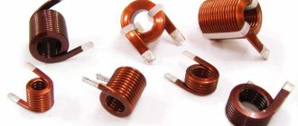
According to their design characteristics, coils can be divided into cylindrical, spiral, toroidal, single-layer, multilayer, with or without a core, shielded, with constant or variable inductance.
On circuit diagrams, next to the conventional graphic image of the inductor, its symbolic letter designation (Latin capital letter L ) with an ordinal digital (sometimes alphabetic) index is placed. The inductance value is usually not indicated on the diagram (Fig. 4.1).
| Inductor | Inductor with taps | Inductors with a magnetic core (L6 - with copper) |
| Shielded inductor | Ferrovariometer | Inductively coupled coils (RF transformer) |
Rice. 4.1. Designations of inductors in diagrams
Chokes have the same graphic image, but are designated by the letters Dr.
Main parameters of high-frequency coils:
Inductance characterizes the amount of magnetic field energy stored in a coil when an electric current flows through it. The unit of inductance is henry (H) and its fractions: millihenry ( mH = 10 -3 H ) and microhenry ( µH = 10 -6 ).
Radio engineering equipment uses high-frequency coils with inductance from fractions of μH to tens of mH. The inductance of the coil depends on its shape, size and number of turns, as well as on the properties of the core or screen.
Quality factor is the ratio of the reactance of the coil to its active loss resistance:
QL = 2πFL/r ,
where r is the equivalent loss resistance in the coil at frequency f .
By analogy with capacitors, energy losses in inductors can be expressed by the loss tangent:
tgδ = r / 2 π FL = 1 / Q.
Most radio devices use coils with a quality factor ranging from 40 to 200.
Self-capacitance is a parasitic (side) parameter of the inductor; it increases losses, reduces stability, and the frequency tuning factor of the circuit.
The temperature coefficient of inductance characterizes the relative change in the inductance of the coil when the temperature changes by 1°C :
TKI = αL = DL(T0) • D T .
Conventional cylindrical coils have TCI = 30...50-10-6 1/°C, and coils with a ceramic frame - 8...16-10-6 1/°C.
The stability of the parameters of the inductors also depends on humidity, atmospheric pressure, etc.
The industry, as a rule, does not produce standard high-frequency coils. Therefore, for equipment for various purposes, the most optimal inductive elements are manufactured.
Graph of current and self-induction EMF versus time
Graphically, the nature of the change in current in the circuit and self-induction EMF over time looks like this:
Dependence of current and self-inductive emf in a coil in an alternating current circuit
The graph shows that the self-induction EMF is greater, the higher the rate of change of current. At the beginning of the period (the area near point 1 on the graph), the current strength increases quickly, and therefore the self-induction emf is maximum here. By the end of the first quarter of the period (point 2), the rate of change decreases almost to zero (the sine wave assumes a horizontal position), after which the current strength decreases more and more rapidly (the section between point 2 and point 3).
Accordingly, the self-induction EMF decreases in point 2 to zero, and then increases again, but at the same time changes its sign to the opposite: now it counteracts the drop in current strength, that is, the current and the EMF coincide in sign. In the next half-cycle the picture repeats.
Calculation of the inductance of some types of high-frequency coils
Here are the calculation formulas for the most commonly used structures.
Inductance of a straight wire with a circular cross-section. This includes inductive elements of the DCV range, assessment of the inductance of the wire leads of resistors, capacitors, active elements:
Lpr = 0.002l(ln [4l/d]-1.75); lLprl = µH ,
where [l] = cm - wire length; d = cm - diameter of the wire without insulation.
Inductance of a round turn of circular wire. Used to evaluate the inductance of loop (resonant) antennas, communication coils, etc.:
Lcr = 0.00628V (ln [8D/d]-1.75),
where [D] = cm is the diameter of the coil.
The inductance of a closed geometric loop will always be less than the inductance of a straight wire of the same length. The greatest inductance is that of the closed geometric contours of the same perimeter that has the largest area. Consequently, the greatest inductance will be in a circuit shaped like a circle.
Inductance of a single-layer cylindrical coil (Fig. 4.2).
Rice. 4.2. Elements of a single-layer cylindrical coil
If the winding length l = m • N ( N is the number of turns ) corresponds to the inequality l >> D , then the formula is acceptable
L = π2 D2 N2 10-3 / l µH.
If the winding length of the coil is commensurate with its diameter, then a correction factor L0 . The value of this coefficient is found from the graph shown in Fig. 4.3, and the inductance value is determined from the expression
L = L0 • N2 • D • 10-3 µH,
Rice. 4.3. Graphical dependence of the correction factor
Inductance of a multilayer cylindrical coil. To obtain large inductance values, multilayer coils are used. The inductance of such coils can be determined using the previous formula, but the correction factor L0 (Fig. 4.4) will depend on the ratio of the winding thickness to the outer diameter t/D .
Rice. 4.4. Correction factor for multilayer coil
Inductance of a coil with a core . The use of cores makes it possible to obtain the optimal value of inductance and quality factor and ensure precise setting of inductance. Inductance of a coil with a core LC = μСL , where L is the inductance of the same coil without a core; μC is the effective magnetic permeability. If μ is the magnetic permeability of the material from which the core is made, then the ratio K μ = μс/μ is the coefficient of use of magnetic properties. It depends on the design of the coil and is determined experimentally.
For ferromagnets (ferrites, carbonyl iron) μс > 1 , for diamagnetic materials (brass, copper, aluminum) μс < 1 . Thus, using ferromagnets increases the inductance of the coil, and using diamagnets decreases it.
The inductance of a toroidal coil (with a ring core) is determined by the formula
Ltor = 0.00628 • μ • N2 (D - √D2T - Dв),
where DT is the diameter of the center line of the torus, cm; DB is the average diameter of the coil; μ is the initial magnetic permeability of the torus material.
Inductance of the shielded coil. Shielding is performed either by shunting the magnetic field with a ferromagnetic screen with a high relative magnetic permeability or by displacing the magnetic field with a diamagnetic screen (copper, brass, aluminum). To shield RF coils, as a rule, the second method is used.
Inductance of a cylindrical coil with an aluminum cylindrical screen
L = L • [1-(D/Dе)3] • [1-(I/2Iе)2],
where L is the inductance of the coil without a screen; D —winding diameter; DE - screen diameter; l —winding length; lE is the length of the screen. The quality factor of a shielded coil is always lower, and its own capacitance is higher than that of a coil without a shield.
Inductance and capacitance
So, first, a little about capacitors. The simplest of them is two metal plates located at some distance from each other (Fig. 1). If you connect a battery to such an element, then after some time it will charge to the same voltage as the battery. In this case, electric charges of different signs will be concentrated on the capacitor plates (Fig. 1). The greater the voltage is applied between the plates, the greater the electrical charge of the plates will be. Since there is air between the plates, and in practice most often some kind of dielectric (non-conducting material), direct current in the circuit in Fig. 1 cannot leak. Materials such as paper, mica, ceramics, various organic films and some others are usually used as dielectrics. The properties of capacitors (primarily frequency ones) depend on the type of dielectric, which we will discuss further in recommendations for their selection. Of course, in practice, a small leakage current still flows through a charged capacitor, caused by the imperfection of the dielectric.
Rice. 1
Electrical capacity itself is a physical quantity that characterizes the ability of a capacitor to accumulate (store) electrical energy. In the dry physico-mathematical language of many textbooks, it is said that electrical capacity C = q / Uc is the coefficient of proportionality between the charge of the capacitor q and the voltage on it Uc = E, where E is the source voltage. This statement, like many similar ones, is strictly from a mathematical point of view, however, unfortunately, it does not reflect the physical nature of the phenomenon.
Capacitance, as you know, is measured in fractions of a farad (the unit is named after the outstanding physicist Michael Faraday). With a capacitor capacity of one farad, the electric charge on any of its plates would be one coulomb, with a voltage between the plates of one volt. In practice, capacitances are usually measured in microfarads, nanofarads and picofarads.
The capacitance of the capacitor depends on the shape and geometric dimensions of the plates, as well as the distance between them and the parameters of the dielectric. Thus, the capacitance of the flat capacitor shown in Fig. 1, is defined as C=ε0εS/d, where ε0 is the electrical constant equal to 8.85·1O12 C2/(Nm2); ε-dielectric constant of the dielectric; d ~ distance between plates; S is the area of the plates. The physical meaning of this formula is quite obvious - the larger the area of the plates and the closer to each other they are located, the greater the capacitance of the capacitor. From this we can draw an important conclusion: when capacitors are connected in parallel, their capacitances add up, since the total area of the plates increases. And the capacitance of series-connected capacitors is also determined as the resistance of parallel-connected resistors, i.e. the final capacitance will be less than the capacitance of each of the series-connected capacitors. In this case, the voltage is distributed between the capacitors in proportion to their capacitance.
Rice. 2
Rice. 3
Electrical energy Wel = CU2c/2 is stored in a charged capacitor. However, the accumulation of electrical charge and, accordingly, energy does not occur instantly. In the electrical circuit shown in Fig. 2, at the moment the switch is closed, a charge current begins to flow, limited by resistance R, which is many times greater in value than the internal resistance of the source, which in this case can be neglected. Then the charge current is determined from Ohm's law: Iз=E/R. There is no voltage on the capacitor Uc=0 (the capacitor, naturally, was not charged before the switch was closed). During the charging of the capacitor, the current in the circuit decreases, and the voltage across the capacitor increases and tends to Uc=E. This is illustrated in the graphs (Fig. 3). In a similar way, the capacitor discharges in the circuit in Fig. 4.
Rice. 4
Rice. 5
Here, the discharge current at the moment the switch is closed jumps from zero to the phase value itimes = E/R, and then smoothly drops to zero again. The voltage on the capacitor smoothly drops from Uc=E to Uc=0 (Fig. 5.). When a capacitor is discharged, all the energy stored in it is converted into thermal energy dissipated by the resistor. Discharge and, accordingly, energy consumption, as well as charge, do not occur instantly, but take a certain time. This rule is called the switching law, which, when applied to circuits with a capacitor, is usually formulated as follows: the voltage across the capacitor cannot change instantly. Indeed, when a capacitor is discharged into a resistor, the voltage across it changes smoothly: Uc = E·EXP(-t/RC). Here the function EXP(x) is an exponential function ex (Euler number e=2.718), more often called an exponential; and the quantity RC is usually called the time constant and is denoted by the Greek letter τ (tau). Indeed, the duration of the discharge depends on this value. The processes of charging and discharging a capacitor are special cases of transient processes.
Now let's move on to inductance. An inductor or inductor is also an energy storage device, only here, unlike a capacitor, the energy of an electric current is converted into the energy of a magnetic field. As is known from physics, a magnetic field is formed around a current-carrying conductor, i.e. An electric field generates a magnetic field. If the conductor is coiled, the magnetic field will increase. This field is proportional to the number of turns in the coil.
The intensity of the magnetic field is characterized by the magnitude of the magnetic flux Ф and the current IL flowing through the coil. The ability of a coil (or conductor with current) to accumulate the energy of a magnetic field is characterized by the value of inductance L, which, again in mathematically strict language, is the coefficient of proportionality between the magnetic flux and the electric current flowing through the coil, generating it L = Ф/IL This value depends only on coil parameters and is measured in henry (H).
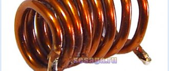
A coil of one henry, when a current of one ampere flows through it, produces a magnetic flux equal to one webber (a unit of measurement for magnetic flux). In practice, the inductance of coils is usually much less than 1 H and is measured in millihenry, microhenry and nanohenry. In DC circuits, the resistance of the coil is determined by the resistive losses in the conductor that forms it and almost no voltage drops across it. In this case, the magnetic field energy stored in the coil can be calculated as follows: WL=L·IL2/2. The inductance (in microhenry) of a single-layer coil (Fig. 6) can be calculated using the following well-known formula: L(μH) = N2 r2/(9r+10l), where N is the number of turns, r is the radius of the turn (frame), l is winding length Multilayer coils have their own calculation formulas. Often, in order to increase the inductance, special cores made of magneto-electric materials - ferrite, permaloy, alsifer, etc. - are introduced into the coils.
Rice. 6
Thus, the coil, like the capacitor, is an energy storage device. In this case, the commutation law must also apply to circuits with inductors, which this time will sound like this: the current in the inductor cannot change instantly. Indeed, when the key is closed in the circuit in Fig. 7, the voltage on the coil will change abruptly to the value E (and then will smoothly drop to zero), and the current will slowly increase according to the same exponential law (Fig. 8.) from zero to the value IL = E/R.
Rice. 7
Rice. 8
So, in the circuit in Fig. 9, when the key is closed, first the light bulb connected to the branch with the resistor will light up, and then, gradually increasing brightness, the light bulb in the inductive circuit will light up. This phenomenon is caused by the fact that, just as an electric field generates a magnetic field, a magnetic field, in turn, generates an electric one. This statement is true only for an alternating magnetic field. This is clearly illustrated by the well-known experiment (Fig. 10), when when a permanent magnet moves along a coil, current flows in its external circuit. This happens in our case: when the key is closed, a small current begins to flow through the coil, causing the appearance of a magnetic flux near its turns, varying in proportion to the increase in current. In turn, this changing magnetic flux leads to the appearance on the coil of an electromotive force of self-induction, switched on according to Lenz’s law in opposition to the force that caused the current. Then the coil will resist the increase in current, as well as its decrease. From physics we can give a lot of examples of when a system resists a change in its stationary state, and the resistance of a coil to a change in current is one of them. As the current increases, energy is stored in the coil, and when it decreases, energy is wasted accordingly. If you abruptly open the circuit in Fig. 7, a strong spark will jump through the key, caused by nothing other than the electromotive force of self-induction.
Rice. 9
Rice. 10
Let's consider how capacitance and inductance behave in alternating (sinusoidal) current circuits. Let a capacitance be included in the alternating current circuit (Fig. 11). Each time the voltage polarity changes, the capacitor will be recharged, i.e. the sign of the charge on each of its plates will change twice the period of the alternating voltage. If the duration of the charge and discharge processes significantly exceeds the period of voltage change, the current in the circuit will also change according to a sinusoidal law, however, the voltage on the capacitor lags in phase with the current by 90° (Fig. 12), which is not surprising, since the capacitor prevents a sharp change voltage. Moreover, during each charge-discharge, the capacitor will either accumulate electrical energy or release some of it to the external circuit. In most cases, a certain electrical energy is constantly stored in a capacitor connected to an alternating current circuit. In a circuit with inductance (Fig. 13), on the contrary, the current is 90° out of phase with the voltage (Fig. 14). This also corresponds to the above reasoning - the coil resists any changes in current. When alternating current flows through the coil, the energy of an alternating magnetic field will be stored in it, leading to the appearance of an alternating electromotive force of self-induction, which prevents the flow of alternating current.
Rice. eleven
Rice. 12
So, a coil in an alternating current circuit resists it as a result of the induced alternating electromotive force of self-induction. At the same time, the capacitor, storing electrical energy, resists alternating current. Both of these resistances are called reactive and are designated by the letter X. Unlike resistive (active) resistance, no thermal energy is dissipated in reactive resistance, but only energy is stored in the form of an electric or magnetic field.
Rice. 13
Rice. 14
The reactances of the coil XL = j·2πf·L and the capacitor XC = -j/2πf·C depend on the frequency f of the flowing alternating current. The imaginary unit j takes into account the 90° phase shift between current and voltage, and the “-” sign indicates that the voltages across the capacitance and inductance connected in series are out of phase. Indeed, when calculating the total complex resistance of a circuit containing inductance and capacitance, inductive resistances must be added with a “+” sign, and capacitive ones, on the contrary, with a “-“ sign. In Fig. Figure 15 shows the dependence of the reactances of inductance and capacitance, as well as their modules, on frequency. At direct current, as is known, inductance has no resistance, and the resistance of a capacitor, on the contrary, tends to be infinitely large. As the frequency increases, the picture changes dramatically - the resistance of the inductor increases linearly, and the resistance of the capacitor decreases according to a curve called a hyperbola.
Rice. 15
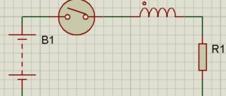
The above properties can be easily explained with an example. In Fig. Figure 16 shows a schematic diagram of the output circuit of a simple radio frequency amplifier. Here, the blocking choke L6n is included in the power supply circuit of the transistor collector, which has a very high resistance at the operating frequency of the amplifier. The purpose of this inductor is not to pass the alternating current of the transistor collector circuit into the power source, which has very low resistance. This alternating current must flow to the load through the decoupling capacitor Cp, which prevents the power supply from shorting to the load (the next stage). This capacitor must be selected in such a way that at the operating frequency of the amplifier it does not provide practically any resistance to alternating current, i.e. its reactance must be at least an order of magnitude (10 times) less than the load resistance. In order for almost all of the alternating current to flow into the load, it is necessary that the reactance of the inductor, on the contrary, be at least an order of magnitude greater than the load resistance. However, since the reactance of the inductor is not infinitely large, a small portion of the alternating current will still pass through it. To prevent this current from entering the power source, a blocking capacitor Sbl is included, which has a very small reactance at the operating frequency.
Rice. 16
Coils, chokes and capacitors find many other different applications in electronic devices. In particular, selective and other oscillatory circuits are built on them, the simplest of which will be discussed next time.
At the end of today’s story, I would like to note another important parameter of coils and capacitors. As we have already said, there are losses in coils and capacitors. In a coil this is the final resistance of the conductor rL, and in a capacitor it is the leakage resistance of the dielectric rth. The presence of these losses leads to partial conversion of the magnetic and electrical energy stored in the coil and capacitor into thermal energy. The magnitude of these losses is characterized by the quality factor Q=X/r, which is defined as the ratio of stored energy to loss energy.
Let's move on to more practical things - how to choose capacitors, chokes, coils for your equipment? Let's start with capacitors. Here it is important to know at least three parameters - electrical capacity, operating voltage (and in some cases, maximum reactive power) and frequency (to within: direct current, audio frequencies, radio frequencies). Regardless of the frequency, any capacitors should be selected for an operating voltage (indicated on the case) that is approximately 1.2 times greater than the maximum voltage applied to this capacitor in the circuit. Despite the fact that the breakdown voltage of the dielectric is usually approximately 1.5 times higher than the specified operating voltage, such a reserve is still necessary. As for the type of dielectric, today in all radio frequency circuits it is necessary to install ceramic capacitors, the range of ratings of which extends from units of picoforads to tens of nanofarads, as blocking and isolating capacitors, as well as filter capacitors. It should be especially noted that capacitors with a high degree of accuracy in the value of their capacitance (no worse than ±5%) should be used as loop capacitors, as well as for other frequency-selective circuits (filters, matching circuits, etc.), but as blocking ones and separating elements, cheaper parts with less accuracy are used. Trimmer capacitors are also usually ceramic, and variable capacitors are made with air or solid synthetic dielectric. Large capacitance values are usually required in low-frequency circuits, where paper capacitors - sealed, etc. - work quite well. The range of values of such capacitors ranges from tens of nanofarads to hundreds of microfarads. Paper capacitors (with capacitances not exceeding units of microfarads) are increasingly being replaced by tantalum semiconductor capacitors. As for mica ones, most of them are currently out of production due to their low technology. These capacitors were produced with capacitance values ranging from hundreds of picofarads to tens of nanofarads. Paper capacitors are also installed in industrial frequency current circuits (as network filters, starting capacitors for engines and neon lamps, etc.). Capacitors with a dielectric based on various organic films stand somewhat apart. They can be used in both low-frequency and radio-frequency equipment, however, at frequencies not exceeding approximately 50, in rare cases 100 MHz. Finally, in DC circuits (in rectifier filters, etc.), the most preferred are electrolytic capacitors, the range of capacitances of which ranges from units of microfarads to tens of millifarads (sometimes more). These capacitors are polar and in alternating current circuits they fail very quickly. As an exception, they can be installed in the circuit of audio amplifiers as isolation circuits, as well as in the bias circuit of low-power cascades.
As for inductors and chokes, when making amateur equipment, as a rule, you have to make them yourself. The exception is high-frequency chokes, which are produced by industry with an inductance of the order of tens to hundreds of micro-henries. These chokes are low-Q and under no circumstances can be used as loop coils and filter inductors. Their main purpose is as blocking chokes for radio frequency amplification stages of low and sometimes medium power (with currents in circuits not exceeding one or two amperes). In powerful cascades of transmitters and other generating equipment, homemade chokes are installed, which are wound with a thick copper wire capable of withstanding the currents flowing in these circuits. This also applies to contour coils of powerful cascades. They should be wound on heat-resistant frames without cores, since the latter are strongly heated by high-frequency eddy currents and significantly reduce the efficiency of the cascade. But when winding loop coils and inductive networks of filters of low-power cascades of transmitters and receivers, frames with cores are usually used - most often ferrite. Alsifer and brass (on VHF) cores are also sometimes used. In the HF and VHF ranges, single-layer winding is used, and at lower frequencies, multi-layer winding is used, and with multi-layer winding, it is advisable to use the “universal” method with crossed turns (as on a bobbin with thread or twine), which allows you to reduce the coil’s own capacitance. As for low-frequency chokes (rectifier filters, etc.), they are most often wound on transformer steel cores or used ready-made from industrial equipment.
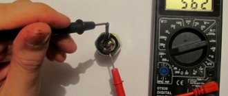
In conclusion, we’ll tell you how to use an old Avometer (pointer tester) to determine the serviceability of coils and capacitors. To test capacitors, the tester should be set to the maximum resistance measurement limit. So, a working capacitor with a capacity of less than 0.1 microfarad should not cause any deviation of the needle, otherwise the capacitor is broken. When testing a capacitor with a capacity of 0.1 ... 10 microfarads, the arrow should jerk to the right and quickly return to the region of infinitely high resistance. Finally, when testing large capacitors (electrolytic, etc.), the tester's needle should deviate sharply to the right (almost to zero resistance), and then slowly return back. A weak surge indicates a loss of capacity. Unfortunately, such a test is almost impossible with digital multimeters due to the lack of a dial indicator, but many of them “can” measure capacitance, which greatly simplifies the task. To check inductors and chokes, the tester must be set to the lower limit of resistance measurement. Loop coils and high-frequency chokes have an ohmic resistance close to zero, and when testing low-frequency chokes (as well as the windings of low-frequency and power transformers), the tester will show a resistance of the order of tens to hundreds of ohms. When testing low-frequency inductive elements, you should avoid touching the conductors with unprotected hands, since at the moment the inductor or transformer is connected to the tester, a self-inductive emf of significant magnitude appears at the terminals.
Optimizing the quality factor of inductors
No less important a parameter than inductance when calculating the inductive components of circuits, filters, and delay lines is their quality factor.
At a given frequency, the quality factor of the inductor is determined by the formula
QL = 2πFL/r ,
where r is the active loss resistance, which has several components. The loss resistance can be represented as the sum
r = r0 + rf + rk + rem + rscreen + rс ,
where r0 is the winding resistance to direct current; rf - high-frequency losses; rk —losses in the frame material; rem - capacitive losses; rscreen —losses in the screen material; rc - losses in the core material.
The resistance of high-frequency losses in the winding consists of losses due to the surface (skin) effect and the proximity effect rf = rskin + rclose . Both of these components have a pronounced dependence on the diameter of the winding wire, as shown in Fig. 4.5. This property is used to obtain maximum quality factor by choosing the optimal diameter of the winding wire.
Rice. 4.5. Optimal winding wire diameter
Dielectric losses arising in the field of the coil's own capacitance through the dielectric are of the same nature as in capacitors and are described by the dielectric loss tangent at the operating frequency.
A high-frequency inductor is an inductor that is included in a circuit to increase resistance to high-frequency currents. Main parameters: zdr - total resistance, R - direct current resistance, Sdr - own capacitance. The impedance at operating frequencies must be large and inductive in nature. The inductor's own capacity (Fig. 4.6) determines its critical frequency fcr = 1/(2p(LdrCdr)1/2 , below which the operating frequency range is located.
Rice. 4.6. Equivalent circuit and dependence of the inductor impedance
HF chokes of the DM type with a ferrite core are commercially produced. Inductance range 1...500 µH. The permissible current value is 60 mA.
Back to the main page … | |
Self-induction
If an alternating current is passed through a closed loop, the magnetic field in the environment can be detected using simple experiments. A change in power parameters is accompanied by the appearance of an induced electromotive force in the circuit. This phenomenon is called self-induction.
The magnitude of the EMF can be calculated using the formula:
E = -L * (Δi/Δt).
This expression shows the dependence of voltage on the change in current per unit time. The correction factor (L) denotes the characteristics of the conductor (induction coil). The sign “-” characterizes the inertial properties of the phenomenon.
When passing a sinusoidal signal, one must take into account the lag of the voltage (vector expression) from the current by 90 degrees. The amplitude will be directly proportional to the frequency (w):
E = L * I * w.