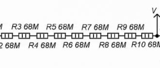
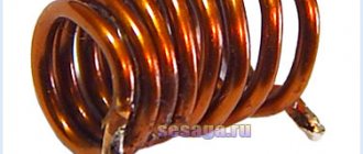
The picture above shows a single layer inductor: D
c is the diameter of the coil,
D
is the diameter of the mandrel or frame of the coil,
p
is the winding pitch of the coil,
d
is the diameter of the wire without insulation and
d
i is the diameter of the wire with insulation
To calculate the inductance LS, use the formula below from the article by R. Weaver, Numerical methods for calculating inductance:
Here
D
- diameter of the mandrel or coil frame in cm,
l
- coil length in cm,
N
- number of turns and
L
— inductance in µH.
This formula is valid only for a solenoid wound with a flat wire. This means that the coil is wound with a very thin tape without any gap between adjacent turns. It is a good approximation for coils with a large number of turns, wound with round wire with a minimum gap between the turns. The American physicist Edward Bennett Rosa (1873–1921) who worked for the US National Bureau of Standards (NBS, now called the National Bureau of Standards and Technology (NIST)) developed the so-called correction factors for the above formula in the form (see formula 10.1 in article by David Knight, David W. Knight):
Here L
S is the inductance of the flat helix described above, and
where k
s is a dimensionless correction factor that takes into account the difference between the self-induction of a coil of round wire and a coil of flat tape;
k
m is a dimensionless correction factor that takes into account the difference in the total mutual inductance of turns of round wire compared to turns of flat tape;
D
c is the diameter of the coil in cm, measured between the centers of the wires and
N
is the number of turns.
The value of the Rosa coefficient k
m is determined by formula 10.18 in the article by David Knight mentioned above:
Rosa coefficient k
s, taking into account the difference in self-induction, is determined by formula 10.4 in the article by D. Knight:
Here p
- winding pitch (distance between turns, measured at the centers of the wires) and
d
- wire diameter.
Note that the p/d
is always greater than one, since the thickness of the wire insulation is finite, and the minimum possible distance between two adjacent turns with very thin insulation, located without a gap, is equal to the diameter of the wire
d
.
Calculation methods
There are several basic ways to determine the inductance of a coil. All formulas that will be used in the calculations can be easily found in reference books or on the Internet. The whole calculation process is quite simple and will not be difficult for people with basic mathematical and physical knowledge.
Through current
This calculation is considered the simplest way to determine the inductance of a coil. The formula through current follows from the term itself. What is the inductance of the coil can be determined by the formula: L=Ф/I, where:
- L - circuit inductance (in Henry);
- F is the magnitude of the magnetic flux, measured in webers;
- I is the current strength in the coil (in amperes).
Finite Length Solenoid
The solenoid is a thin long coil, where the thickness of the winding is significantly less than the diameter. In this case, calculations are carried out using the same formula as through current strength, only the magnitude of the magnetic flux will be determined as follows: Ф=µ0NS/l, where:
- µ0 is the magnetic permeability of the medium, determined from lookup tables (for air, which is taken by default in most calculations, it is equal to 0.00000126 henry/meter);
- N is the number of turns in the coil;
- S is the cross-sectional area of the coil, measured in square meters;
- l is the length of the solenoid in meters.
The self-induction coefficient of the solenoid can also be calculated based on the method for determining the energy of the magnetic flux of the field. This is a simpler option, but it requires some quantities. The formula for finding inductance is L=2W/I 2, where:
- W is the magnetic flux energy, measured in joules;
- I is the current strength in amperes.
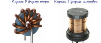
Toroidal core coil
In most cases, a toroidal coil is wound on a core made of a material with high magnetic permeability. In this case, to calculate the inductance, you can use the formula for a straight solenoid of infinite length. It has the following form: L=N µ0 µS/2 πr, where:
- N is the number of coil turns;
- µ—relative magnetic permeability;
- µ0—magnetic constant;
- S is the cross-sectional area of the core;
- π is a mathematical constant equal to 3.14;
- r is the average radius of the torus.
Long conductor
Most of these quasi-linear conductors have a circular cross-section. In this case, the value of the self-induction coefficient will be determined by the standard formula for approximate calculations: L= µ0l (µelnl/r+ µi/4)/2 π. The following notations are used here:
- l is the length of the conductor in meters;
- r is the radius of the wire cross-section, measured in meters;
- µ0—magnetic constant;
- µi is the relative magnetic permeability characteristic of the material from which the conductor is made;
- µe is the relative magnetic permeability of the external environment (most often the value for vacuum is taken to be 1);
- π—pi number;
- ln is the notation for logarithm.
Loop Inductance - Theory
Inductance is an idealized element whose properties are similar to an inductive coil, in which the energy of a magnetic field is accumulated.
Symbol of inductance and positive directions of current, EMF of self-induction and voltage:
If a current is passed through a conductor, a magnetic flux Φ is created around it. The total magnetic flux (clutch flux) of the inductor is equal to Ψ= w×Φ, where Φ is the magnetic flux created by one turn; w is the number of turns.
By definition, self-inductance (or simply inductance) is equal to the proportionality coefficient between flux linkage and coil current L=Ψ/i.
Inductance is measured in Henry 1 H = 1 Wb / 1 A. The symbol L used to denote inductance was adopted in honor of Heinrich Friedrich Emil Lenz. The unit of inductance is named after Joseph Henry. The term inductance itself was coined by Oliver Heaviside in February 1886.
The coupling flux of the inductor is Ψ=L×i.
In accordance with the law of electromagnetic induction, when the magnetic flux changes in the coil, a self-inductive emf eL=-dΨ/dt is induced. The “-” sign is placed because the EMF has such a direction that the current it generates with its magnetic field prevents the change in the magnetic flux that causes this EMF.
The voltage across the inductance balances the EMF and can be written as uL=-eL=dΨ/dt=L×di/dt.
The instantaneous power entering the inductor is equal to p=uL×i=L×i×di/dt.
The energy stored in the inductor is wM=∫(0^t)ptd=∫(0^t)L×i×dt×di/dt=(L×i²)/2.
Mutual inductance characterizes the property of one element with current i1 to create a magnetic field that partially meshes with the turns w2 of another element.
The coefficient of mutual inductance is determined by the formula M=Ψ12/i2=Ψ21/i1, where Ψ12 is the coupling flux of the first circuit caused by the current of the second circuit (similar to Ψ21). Measured in Gn.
Single turn circuit and coil
The inductance of a loop representing a turn of wire depends on the amount of current flowing and the magnetic flux passing through the loop. For the inductance of the circuit, the formula determines the parameter, respectively, through the flux and current strength:
L=F/I.
The weakening of the magnetic flux due to the diamagnetic properties of the environment reduces the inductance.
The parameter for a multi-turn coil is proportional to the square of the number of turns, since not only the magnetic flux from each turn increases, but also the flux linkage:
L=L1∙N2.
In order to calculate the inductance of a coil, the formula must take into account not only the number of turns, but also the type of winding and geometric dimensions.
How to find loop inductance
The formula, which is the simplest for finding the value, is the following:
- L=F:I,
where F is the magnetic flux, I is the current in the circuit.
Self-inductive emf can be expressed through inductance:
- Ei = -L x dI : dt.
The formula suggests a conclusion about the numerical equality of induction with EMF, which occurs in the circuit when the current changes by one ammeter in one second.
Variable inductance makes it possible to find the energy of the magnetic field:
- W = L I2 : 2.
What is inductance
This term denotes the relationship that is established between the current strength in the conductor (I) and the created magnetic flux (F):
L = Ф/ I.
Given the basic definition, it is not difficult to understand the dependence of inductance on the properties of the environment, which influences the distribution of power lines. The dimensions and configuration of the conductive element have a certain significance.
Inductance is similar to mechanical inertia. Only in this case we are talking about actions with electrical quantities. This coefficient characterizes the ability of the component in question to resist changes in the current passing through it.
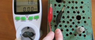
Multimeter attachment housing
The body can be made from a ready-made box of a suitable size, or you can make the box yourself. You can choose any material, such as plastic or thin fiberglass. The box is adapted to the size of the table and has holes for mounting. There are also holes for connecting wiring. Everything is fixed with screws.
The set-top box is powered from the mains via a 12 V power supply.
induced emf
Let us understand in detail what the concept of induced emf is. When a conductor is placed in a magnetic field and moves with the intersection of field lines, an electromotive force called induced emf appears in the conductor. It also occurs if the conductor remains stationary, and the magnetic field moves and intersects the conductor with lines of force.
When the conductor where the EMF occurs is closed to the external circuit, due to the presence of this EMF, an induced current begins to flow through the circuit. Electromagnetic induction involves the phenomenon of inducing an EMF in a conductor at the moment it is crossed by magnetic field lines.
Electromagnetic induction is the reverse process of transforming mechanical energy into electric current. This concept and its laws are widely used in electrical engineering; most electric machines are based on this phenomenon.
Introduction
If someone came up with the idea of conducting a survey of the world's population on the topic “What do you know about inductance?”, the overwhelming number of respondents would simply shrug their shoulders. But this is the second most numerous technical element, after transistors, on which modern civilization is based! Detective fans, remembering that in their youth they read Sir Arthur Conan Doyle’s exciting stories about the adventures of the famous detective Sherlock Holmes, will, with varying degrees of confidence, mutter something about the method that the above-mentioned detective used. At the same time, implying the method of deduction, which, along with the method of induction, is the main method of knowledge in Western philosophy of the New Age.
With the induction method, individual facts, principles are studied and general theoretical concepts are formed based on the results obtained (from particular to general). The deduction method, on the contrary, involves research from general principles and laws, when the provisions of the theory are distributed into individual phenomena.
It should be noted that induction, in the sense of method, does not have any direct relation to inductance, they simply have a common Latin root inductio
- guidance, motivation - and mean completely different concepts.
Only a small part of those surveyed from among the exact sciences - professional physicists, electrical engineers, radio engineers and students in these fields - will be able to give a clear answer to this question, and some of them are ready to give an entire lecture on this topic right away.
Definition of inductance
In physics, inductance, or the coefficient of self-induction, is defined as the coefficient of proportionality L between the magnetic flux Ф around a current-carrying conductor and the current I generating it, or - in a more strict formulation - this is the coefficient of proportionality between the electric current flowing in any closed circuit and the magnetic flux created by this current:
Ф = L·I
or
L = Ф/I
To understand the physical role of the inductor in electrical circuits, one can use the analogy of the formula for the energy stored in it when current I flows with the formula for the mechanical kinetic energy of the body.
For a given current I, inductance L determines the energy of the magnetic field W created by this current I:
WI
= 1/2
L
I
2
Similarly, the mechanical kinetic energy of a body is determined by the mass of the body m and its speed V:
Wk
= 1/2 ·
m
·
V
2
That is, inductance, like mass, does not allow the energy of the magnetic field to instantly increase, just as mass does not allow this to happen with the kinetic energy of the body.
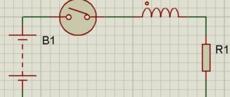
Let's study the behavior of current in inductance:
Rice. 1. Electrical diagram of the experiment
Rice. 2. Physical implementation of the experiment
Rice. 3. Oscillogram of current through inductance. The yellow oscillogram is the output of the signal generator, the blue one is the signal at the resistor.
Due to the inertia of the inductance, the fronts of the input voltage are delayed. In automation and radio engineering, such a circuit is called an integrating circuit, and is used to perform the mathematical operation of integration.
Let's study the voltage on the inductor:
Rice. 4. Electrical diagram of the experiment
Rice. 6. Voltage oscillogram across the inductance (blue)
At the moments of applying and removing voltage, due to the self-inductive emf inherent in the inductance coils, voltage surges occur. Such a circuit in automation and radio engineering is called differentiating, and is used in automation to correct processes in a controlled object that are fast in nature.
Rice. 5. By and large, in all electric current generators of any type, as well as in electric motors, their windings are inductor coils.
Application of coils in technology
The phenomenon of electromagnetic induction has been known for a long time and is widely used in technology. Examples of using:
- smoothing out ripples and interference, storing energy;
- creation of magnetic fields in various devices;
- feedback circuit filters;
- creation of oscillatory circuits;
- transformers (a device of two coils connected inductively);
- power electrical engineering uses to limit the current during a short circuit. on power lines (inductors called reactors);
- limiting the current in welding machines - inductance coils make its operation more stable, reducing the arc, which allows you to get an even welding seam that has the greatest strength;
- the use of coils as electromagnets of various actuators;
- electromagnetic relay windings;
- induction furnaces;
- establishing the quality of iron ores, studying rocks by determining the magnetic permeability of minerals.
Areas of application
What is inductance is clear, but where can it be used? In general, you can find them in almost every electrical appliance. For example, they are found everywhere in power supplies.
In current sources, during operation, the voltage decreases/increases, for which the transformer is responsible - essentially 2 or more coils connected in series. Moreover, with increasing cyclic frequency, efficiency increases.
For example, airplanes use 400 Hz transformers instead of household and industrial 60 Hz transformers.
They can also be found in:
- electrical filters;
- charging device;
- heaters;
- electric magnets;
- Large home appliances.
Solenoid
The solenoid differs from a conventional coil in two ways:
- The length of the winding exceeds the diameter several times;
- The thickness of the winding is also several times smaller than the diameter of the coil.
Solenoidal coil type
The parameters of the solenoid can be found from the following expression:
L=µ0N2S/l,
Where:
- µ0 – magnetic constant;
- N – number of turns;
- S – cross-sectional area of the winding;
- l – winding length.
Important! The above expression is valid for a solenoid without a core. Otherwise, it is necessary to additionally introduce a factor µ, which is equal to the magnetic permeability of the core
The greater the magnetic permeability of the core, the more the final value will increase.
Necessary formulas for calculations
To find the inductance of the solenoid, the following formula is applied:
- L= µ0n2V,
where µ0 shows the magnetic permeability of the vacuum, n is the number of turns, V is the volume of the solenoid.
You can also calculate the inductance of the solenoid using another formula:
- L = µ0N2S : l,
It will be interesting➡ What is an autotransformer?
where S is the cross-sectional area and l is the length of the solenoid.
To find the inductance of the solenoid, any formula is used that is suitable for solving the given problem.
registry
RESULTS ¾Ð¹ ÑкамÑи. RESULTS µÑ. RESULTS ÑпоÑобно воздейÑÑвоваÑÑ Ð½Ð° п ÑедмеÑÑ, пÑиÑÑÐ³Ð¸Ð²Ð°Ñ Ð¸Ð»Ð¸ оÑÑÐ°Ð»ÐºÐ¸Ð²Ð°Ñ Ð¸Ñ. Ðо, помимо ÑÑого, Ñ Ñ Ð½ÐµÐ³Ð¾ еÑÑÑ Ð¸ дÑÑгие оÑобРµÐ½Ð½Ð¾ÑÑи: напÑимеÑ, магниÑное поле Ð¼Ð¾Ð¶ÐµÑ Ð ²Ð¾Ð·Ð´ÐµÐ¹ÑÑвовР°ÑÑ Ð½Ð° ÑлекÑÑиÑеÑки заÑÑженнÑе обÑекÑ, а ÑÑо з наÑиÑ, ÑÑо ÑлекÑÑиÑеÑÑво и магнеÑизм ѵÑно ÑÐÑ ²Ñз › RESULTS: ROOM RESULTS м ÑÐ"овом - "ÑÐ"екÑÑомагниÑнÑе ÑвÐ"ениÑ". REPORT ¾ ROOM RESULTS. ROOM ROOM RESULTS °Ð»Ð°Ñ ÑаÑÑÑ Ñого, ÑÑо извеÑÑно ÑеловеÑеÑÑÐ²Ñ Ð¾ мР°Ð³Ð½ÐµÑизме ÑегоднÑ.
Ð ÑейÑÐ°Ñ Ð¿ÐµÑейдÑм неп¾ÑÑедÑÑвенно к пÑед RESULTS. RESEARCH ¸Ñ ROOM ÑивноÑÑи.
"Spool of thread"
An inductor is an insulated copper wire wound on a solid base. As for insulation, the choice of material is wide - varnish, wire insulation, and fabric. The magnitude of the magnetic flux depends on the area of the cylinder. If you increase the current in the coil, the magnetic field will become larger and vice versa.
If you apply an electric current to a coil, a voltage appears in it opposite to the current voltage, but it suddenly disappears. This kind of voltage is called electromotive force of self-induction. At the moment the voltage is turned on to the coil, the current changes its value from 0 to a certain number. The voltage at this moment also changes its value, according to Ohm’s law:
I = U : R,
where I characterizes the current strength, U indicates the voltage, R is the coil resistance.
Another special feature of the coil is the following fact: if you open the circuit “coil - current source”, the EMF will be added to the voltage. The current will also initially increase and then decline. This implies the first law of commutation, which states that the current strength in the inductor does not change instantly.
The coil can be divided into two types:
- With magnetic tip. The material of the heart is ferrites and iron. The cores serve to increase inductance.
- With non-magnetic. Used in cases where the inductance is no more than five milliHenry.
The devices differ in appearance and internal structure. Depending on these parameters, the inductance of the coil is determined. The formula is different in each case. For example, for a single-layer coil the inductance will be equal to:
L = 10µ0ΠN2R2 : 9R + 10l.
But for a multilayer one there is another formula:
L= µ0N2R2 :2Π(6R + 9l + 10w).
Main conclusions related to the operation of coils:
- On a cylindrical ferrite, the largest inductance occurs in the middle.
- To obtain maximum inductance, it is necessary to wind the turns closely on the coil.
- The smaller the number of turns, the smaller the inductance.
- In a toroidal core, the distance between the turns does not play the role of the coil.
- The inductance value depends on the “turns squared”.
- If inductances are connected in series, then their total value is equal to the sum of the inductances.
- When connecting in parallel, you need to ensure that the inductances are spaced apart on the board. Otherwise, their readings will be incorrect due to the mutual influence of magnetic fields.
Set-top box assembly
You can assemble a tester connecting to a multimeter to measure inductance without problems at home if you have basic knowledge and skills in the field of radio engineering and soldering of microcircuits.
In the circuit, you can use transistors KT361B, KT361G and KT3701 with any letter designations, but for more accurate measurements it is better to use transistors marked KT362B and KT363.
These transistors are installed on the board in positions VT1 and VT2. In position VT3 it is necessary to install a silicon transistor with a pnp structure, for example, KT209V with any letter marking. Positions VT4 and VT5 are for buffer amplifiers.
Most high-frequency transistors are suitable, with h21E parameters for one not lower than 150, and for the other higher than 50.
Any high frequency silicon diode will be suitable for positions VD and VD2.
The resistor can be chosen MLT 0.125 or similar. Capacitor C1 is taken with a nominal capacity of 25330 pF, since it is responsible for the measurement accuracy, and its value should be selected with a deviation of no more than 1%.
Such a capacitor can be made by combining thermally stable capacitors of different capacitances (for example, from 2 to 10,000 pF, from 1 to 5100 pF and from 1 to 220 pF). For other locations, any small-sized electrolytic and ceramic capacitors with an acceptable spread of 1.5-2 times are suitable.
The contact wires to the board (position X1) can be soldered or connected using spring clamps for "speaker" wires. Connector X3 is intended for connecting the set-top box to a multimeter (frequency meter).
It is best to use shorter wire for bananas and alligators to reduce the effect of inductance on the measurement readings. In the place where the wires are soldered to the board, the connection must be additionally secured with a drop of hot glue.
If you need to adjust the measuring range, you can add a switch connector (eg three ranges) to the card.
Basic formulas for calculating the MI vector
The magnetic induction vector, the formula of which is B = Fm/I*∆L, can be found using other mathematical calculations.
Biot-Savart-Laplace Law
Describes the rules for finding B→ magnetic field, which creates a constant electric current. This is an experimentally established pattern. Biot and Savard identified it in practice in 1820, Laplace managed to formulate it. This law is fundamental in magnetostatics. During the practical experiment, a stationary wire with a small cross-section was considered, through which an electric current was passed. For study, a small section of wire was selected, which was characterized by the vector dl. Its module corresponded to the length of the section under consideration, and its direction coincided with the direction of the current.
Interesting. Laplace Pierre Simon proposed to consider even the movement of one electron as a current and, based on this statement, using this law, he proved the possibility of determining the magnetic field of an advancing point charge.
According to this physical rule, each segment dl of a conductor through which electric current I flows forms a magnetic field dB in the space around itself at an interval r and at an angle α
dB = µ0 *I*dl*sin α /4*π*r2,
Where
- dB – magnetic induction, T;
- µ0 = 4 π*10-7 – magnetic constant, H/m;
- I – current strength, A;
- dl – conductor section, m;
- r – distance to the point where the magnetic induction is located, m;
- α is the angle formed by r and the vector dl.
Important! According to the Biot-Savart-Laplace law, by summing the magnetic field vectors of individual sectors, it is possible to determine the MF of the desired current. It will be equal to the vector sum
Biot-Savart-Laplace Law
There are formulas that describe this law for individual cases of MP:
- fields of direct movement of electrons;
- fields of circular motion of charged particles.
The formula for MP of the first type is:
B = µ* µ0*2*I/4*π*r.
For circular motion it looks like this:
B = µ*µ0*I/4*π*r.
In these formulas, µ is the magnetic permeability of the medium (relative).
The law under consideration follows from Maxwell's equations. Maxwell derived two equations for the magnetic field; the case where the electric field is constant is considered by Biot and Savart.
Superposition principle
For MF, there is a principle according to which the total vector of magnetic induction at a certain point is equal to the vector sum of all MI vectors created by different currents at a given point:
B→= B1→+ B2→+ B3→… + Bn→
Superposition principle
Circulation theorem
Initially, in 1826, Andre Ampère formulated this theorem. He analyzed the case with constant electric fields, his theorem is applicable to magnetostatics. The theorem states: the circulation of MF of direct electricity along any circuit is proportional to the sum of the forces of all currents that penetrate this circuit.
Worth knowing! Thirty-five years later, D. Maxwell generalized this statement, drawing parallels with hydrodynamics.
Another name for the theorem is Ampere’s law, which describes the circulation of MP.
Mathematically, the theorem is written as follows.
Mathematical formula of the circulation theorem
Where:
- B→– magnetic induction vector;
- j→ – electron motion density.
This is the integral form of writing the theorem. Here, on the left side one integrates along a certain closed contour, on the right side - along a stretched surface onto the resulting contour.
Magnetic flux
One of the physical quantities characterizing the level of magnetic field crossing any surface is magnetic flux. It is designated by the letter φ and has a unit of measurement called Weber (Wb). This unit is characteristic of the SI system. In the GHS, magnetic flux is measured in maxwells (Mks):
108 μs = 1 Wb.
Magnetic flux φ determines the magnitude of the magnetic field penetrating a certain surface. The flux φ depends on the angle at which the field penetrates the surface and the strength of the field.
The formula for calculation is:
φ = |B*S| = B*S*cosα,
Where
- B is the scalar value of the magnetic induction gradient;
- S – area of the intersected surface;
- α is the angle formed by the flow Ф and the perpendicular to the surface (normal).
Attention! Flux Ф will be greatest when B→ coincides with the normal in direction (angle α = 00). Similar to Ф = 0, when it runs parallel to the normal (angle α = 900)
Magnetic flux
The magnetic induction vector, or magnetic induction, indicates the direction of the field. Using simple methods: the gimlet rule, a freely oriented magnetic needle or a circuit with a current in a magnetic field, you can determine the direction of action of this field.
Graphical output of the formula
It is possible to obtain the written formula using the graphical method. To do this, let us display on a graph the dependence of the magnetic flux Φ(I) on the current I (Fig. 1.21.2). The total amount of heat released, which is equal to the initial energy reserve of the magnetic field, is determined as the area of the resulting figure in Fig. 1.21.2 triangles:
Figure 1.21.2. Calculation of magnetic field energy.
As a result, the formula for the energy Wm of the magnetic field of a coil with inductance L, created by current I, will be written as the formula:
Wм=ΦI2=LI22=Φ22L
Let's use the expression we got for the coil energy to a long solenoid with a magnetic core. Applying the above formulas for the self-induction coefficient Lμ of the solenoid and for the magnetic field B created by the current I, we obtain the entry:
Wм=μ0·μ·n2·I22V=B22μ0·μV
In this formula, V is the volume of the solenoid. The resulting expression demonstrates to us that magnetic energy is not localized in the turns of the coil through which the current passes, but is distributed throughout the entire volume in which the magnetic field arose.
Definition 4
Volumetric magnetic energy density is a physical quantity that is equal to the magnetic field energy per unit volume: Wм=B22μ·μ.
At one time, Maxwell demonstrated that the indicated formula (in our case, derived for a long solenoid) is correct for any magnetic fields.
RESPONSIBILITY
RESULTS sunny, sloping ·Ð¸ÐºÐµ, каÑÑÑки Ñвзи, иÑполÑзÑемÑе в ÑÑанÑÑоÑм аÑоÑаÑ, и ваÑиомеÑÑÑÑ, Ñо еÑÑÑ ÐºÐ°ÑÑÑки, покР· ›
RESULTS SÑели. RESULTS ±ÑÑнÑе и ÑдвоеннÑе. ROOM - RESULTS ¸ÑÑ ÑоÑоÑим ÑиДÑÑÑом, пÑопÑÑкаÑÑим поÑÑоÑннÑÐ ¹ ок и задеÑживаÑÑим пеÑеменнÑй OPTIONAL CONDITIONS ºÑивноÑÑÑÑ Ð¿¿Ñи болÑÑÐ¸Ñ ÑÐ¾ÐºÐ°Ñ Ð¸ Ñ°ÑÑоÑÐ°Ñ Ð¿Ð¾ ÑÑÐ°Ð²Ð½ÐµÐ½Ð¸Ñ Ñ Ð¾Ð±ÑÑнÑми.
Variometer
What a coil is is shown above using simple examples. In practice, specific terminology is used to designate groups of the same type. A variometer, for example, is a part with variable inductance. In a typical design, two coils are used, installed one inside the other. The required result is obtained by adjusting the relative position of the functional components. For movement, a manual drive or an automated mechanism with an external control circuit is used.
For your information. The definitions should not be confused. A baitcasting reel, for example, is a fishing device. Such a device will have inductance when winding a fishing line from a conductive material. However, such devices are not used in radio circuits.
Multiplier reels
Features of other designs:
- The inductor provides high circuit resistance to alternating current, so such a passive inductive element is often used to create filters. When connecting to a 220V/50 Hz power supply, iron cores are used. As the frequency increases, ferrite analogues are used.
- Magnetic loop coils are installed in combination with capacitors to create circuits with a specific bandwidth.
- An electric reactor is a name given to large structures that are used in power networks.
- Double coils are used to separate circuits by DC component.
The current reactor limits high current, prevents the development of an emergency situation during a short circuit.
Typical areas of application of elements with inductive characteristics are noted above. They are suitable for creating filters, limiting current and separating the passage of DC and AC signal components. The magnetic field of a current-carrying coil propagates in space. To prevent parasitic interference, the individual components are placed at a sufficient distance.
RF detector attachment for multimeter
The simplest circuit of an attachment to a digital multimeter for measuring RF alternating current. Suitable for measuring the power of an audio amplifier or radio transmitter. The multimeter must be integrated with a simple external measuring head containing a high-frequency germanium diode detector. This circuit rectifies and filters the AC signal voltage, converting it into an easily measurable DC voltage.
The input capacitance of the RF head is less than 3 pF, which allows it to be connected directly to a cascade circuit. You can use Soviet high-frequency diodes D9, GD507 or D18. The RF head is assembled in a shielded housing on which terminals are located for connecting the probe or wires to the circuit being measured. Communication with the tester must be carried out using a shielded television cable.
RESULTS
RESULTS µÐ³Ð¾ ÐиÑÐ°Ñ Ð¸ ÐÑевней ÐÑеÑии. RESULTS RESULTS , ASSURANCE. RUSSIAN RESEARCH ROOM
1820 1820 1820 ASSURANCE. RESULTS RESULTS ° ÑевеÑ. 1820 1820 ROOM RESULTS. RESULTS ½ÑÑ, взÑвÑиÑÑÑ Ð·Ð° ÑÑо вÑеÑÑÑз·, ÑÑÐ¾Ð±Ñ ÑазÑабоÑÐ °ÑÑ ÑеоÑÐ¸Ñ Ð¼Ð°Ð³Ð½Ð¸Ñного полÑ.
11 11 1831 1831 1831 1831 UR › › › µ поле». RESULTS registry, regurgitation Ð¾Ð´Ð½Ñ Ð ¸ пойдÑÑ ÑеÑÑ.
RESULTS ³Ð¾ ÑÑÑÑойÑÑва ÑÑÐ¸Ñ ÐºÐ°ÑÑÑек, оÑвежим в голове понÑÑие магниÑного полÑ.
General information
In order to understand what the inductance of the coil depends on, it is necessary to study in detail all the information about this physical quantity. The first step is to consider the accepted international designation of the parameter, its purpose, characteristics and units of measurement.
The first letter of the surname of another famous physicist, Emilia Lenza, was taken as a designation for inductance in formulas and when carrying out calculations. Today, the symbol L continues to be used when referring to this parameter.
The outstanding American physicist Joseph Henry was the first to discover the phenomenon of inductance. In his honor, physicists named the unit of measurement in the international SI, which is most often used in calculations. In other systems (Gaussian and SGS), inductance is measured in centimeters. To simplify the calculations, a relationship was adopted in which 1 cm equals 1 nanohenry. The very rarely used SGSE system leaves the self-induction coefficient without any units of measurement or uses the stathenry value. It depends on several parameters and is approximately equal to 89875520000 henry.
Among the main properties of inductance are:
- The parameter value can never be less than zero.
- The indicator depends only on the magnetic properties of the coil core, as well as on the geometric dimensions of the circuit.
Digital multimeter
Unlike analogue ones, this multimeter allows you to easily determine the quantities of interest, while its measurement accuracy is much higher than that of pointer instruments.
In addition, the presence of a switch between different characteristics of electricity eliminates the possibility of confusing one value or another, since the user does not need to understand the gradation of the indication scale.
The measurement results are displayed on the display (in older models - LED, and in modern ones - liquid crystal). For this reason, the digital multimeter is user-friendly for professionals and simple and intuitive for beginners.
Properties of magnetism
The magnetic field, like any other physical phenomenon on Earth, has its own characteristics:
- The source of its occurrence is moving electrical charges.
- Magnetic field induction is its main force characteristic, which exists at each individual point and is directional.
- Its influence is limited to magnets, moving charges and current conductors.
- Scientists divide it into two types: constant and variable.
- A person without special devices cannot feel the effects of magnetism.
- This is an electrodynamic phenomenon, because its source is moving particles of electric current. And only the same particles can be influenced by a magnetic field.
- The trajectory of charged particles can only be perpendicular.
Magnetic induction lines
The magnetic field induction itself is characterized by a certain direction, which is represented by lines displayed graphically. These lines are also called magnetic lines, or magnetic field lines. Just like magnetic induction, its lines have their own definition. They are lines to which tangents are drawn at all points of the field. These tangents and the magnetic induction vector coincide with each other.
A uniform magnetic field is distinguished by parallel lines of magnetic induction, coinciding with the direction of the vector at all points.
If the magnetic field is non-uniform, the electromagnetic induction vector will change at each spatial point located around the conductor. Tangents drawn to this vector will result in the creation of concentric circles around the conductor. Thus, in this case, the induction lines will look like expanding circles.
Analog multimeter
This type of multimeter displays measurement readings using a arrow, underneath which is a display with different scales of values.
Each scale shows the readings of one or another measurement, which are signed directly on the scoreboard. But for beginners, such a multimeter will not be the best choice, since it is quite difficult to understand all the symbols that are on the display. This may lead to misunderstanding of the measurement results.
Core material
As in the previous example, to calculate the induction of a coil with a core, the relative magnetic permeability multiplier “m” is added to the above formulas
L = m0 * m * N2 * (S/l) = m0 * m * n2 * V.
Using this coefficient, the ferromagnetic properties of a certain material are taken into account.
If, for example, we take an endless (very long) straight wire with a circular cross-section, then it will have a certain inductance:
L = (m0/2π) * l *(mc * ln(l/r) +1/4m,
Where:
- mc – magnetic permeability (relative) of the medium;
- r is the radius, which is much less than the length (l) of the conductor.
However, simple dependencies only operate up to a certain frequency. From a certain level, short waves begin to propagate in the surface part of the conductors (skin effect). Additionally, it is necessary to take into account the influence of vortex components that screen radiation and change the force parameters of the field.
Modern magnetic materials
The coil will work exactly as designed if all functional components of the design are correctly selected. As shown above, core parameters are essential. Important features of the relevant materials are noted below:
- Steel with low impurity content is inexpensive. It is recommended for use in DC circuits, since losses increase significantly with increasing frequency.
- Silicon is added to special grades (transformer steel). To reduce the harmful effects of surface effects, the core is assembled from plates. However, such solutions should not be used at frequencies above 1 kHz.
- Alloys made of iron and nickel are characterized by increased magnetic permeability. Operating range – up to 80-120 kHz.
- Powder materials are created with a layer of dielectric on the surfaces of individual microscopic granules. They are well suited for working with high-frequency signals, but do not have high magnetic permeability.
- Ferrites are materials created on the basis of ceramic components. They have good technical characteristics and low losses. It is necessary to take into account the significant dependence on temperature, as well as the deterioration of operating parameters during long-term operation.
Measuring the inductance of a coil made of copper wire on a ferrite core
Designation and units of measurement
Current resistance: formula
In honor of Lenz, the unit of inductance was designated by the symbol "L". Expressed as Henry, abbreviated as Gn (in English literature N), in honor of the famous American physicist.
Joseph Henry
If, with a current change of one ampere for every second, the self-inductive emf is 1 volt, then the inductance of the circuit will be measured in 1 henry.
How can inductance be designated in other systems:
- In the SGS system, SGSM - in centimeters. To distinguish it from the unit of length, it is designated abhenry;
- In the SGSE system - in StatHenry.