LM317 is an adjustable voltage stabilizer. It can be used to create various power supplies. It can be the basis for a current stabilizer, charger, laboratory power supply and even an audio amplifier. In order to use it, it is enough to connect it to one of the wiring diagrams indicated below.
This microcircuit is one of the most popular in the world - all because of the simplicity of its design and operation, its low cost and reliability. The latter is ensured by the presence of protection for short circuit of the terminals and overheating of the microcircuit. LM317 does not require many components as a harness. The microcircuit gained the greatest popularity among radio amateurs.
LM317 regulates voltage linearly, which is its advantage over switching converters. The microcircuit is sold in several housing options, the most popular is the LM317T version in the TO-220 housing. It was developed by Bob Dobkin in 1976 while he was working at National Semiconductor, and has been a hit in ham radio circles ever since.
LM317 circuit
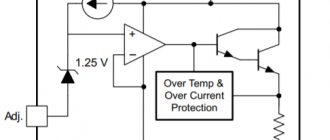
The entire internal structure of the stabilizer can be seen on its diagram, taken in the datasheet. It shows three pins of the circuit: input (power is supplied to this input), regulation and output. At the adjustment pin, the signal voltage is first reduced by a one-way limiter to a stable 1.25V and serves as a reference source, and the current, along with the supply current, goes to a comparator based on an operational amplifier.
Also in the diagram you can see an output stage based on a bipolar transistor, which amplifies the current, and a protection unit against overheating and overcurrent.
To the right of the protection unit there is a current sensor, a drop in which is monitored by the protection in order to prevent damage from short circuits.
Hero of the review:
The lot consists of 10 microcircuits in a TO-220 package. The stabilizers came in a plastic bag wrapped in polyethylene foam.
Comparison with probably the most famous linear stabilizer 7805 for 5 volts in the same housing.
Testing:
Similar stabilizers are produced by many manufacturers, here is a link to a manual from Texas Instruments. The position of the legs is as follows:
1 - adjustment; 2 - exit; 3 - entrance. We assemble a simple voltage stabilizer according to the diagram from the manual:
The results, frankly speaking, are not very good. I wouldn't dare call it a stabilizer. Next, I loaded the stabilizer with a 25 Ohm resistor and the picture completely changed:
Next, I decided to check the dependence of the output voltage on the load current, for which I set the input voltage to 15V, set the output voltage to about 5V using a trimmer resistor, and loaded the output with a variable 100 Ohm wirewound resistor. Here's what happened:
It was not possible to obtain a current of more than 0.8A, because The input voltage began to drop (the power supply is weak). As a result of this testing, the stabilizer with the radiator heated up to 65 degrees:
To check the operation of the current stabilizer, the following circuit was assembled:
Current stabilization is also good.
Well, how can there be a review without burning the hero? To do this, I reassembled the voltage stabilizer, applied 15V to the input, set the output to 5V, i.e. 10V dropped on the stabilizer, and loaded it at 0.8A, i.e. 8W of power was released on the stabilizer. The radiator was removed. The result was demonstrated in the following video: Yes, the overheating protection also works, it was not possible to burn the stabilizer.
Characteristics of LM317
- Maximum input voltage LM317 – 40V
- LM317 output voltage range – 1.2-37V
- Maximum output current for LM317 – 1.5A
- The reference voltage of the microcircuit is 0.1-1.3V
- Minimum load current – 3.5mA
- Output voltage error – 0.1%
- Power dissipation – 20W
- Operating temperature range – 0-125C
- Storage temperature range – -65-150C
- Storage temperature range – -65-150°C
Types of LM317
The microcircuit is sold in several housing options, depending on the need for size, load and connection, as well as the type of circuit installation - everyone can choose the option that suits them best.
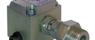
The most popular is the LM317T in a TO-220 1.5 Ampere package. This is considered a universal option, as it can be used in surface-mounted as well as surface-mounted applications. A radiator in such a case allows you to remove excess heat and experience more severe loads than its counterparts, and if necessary, it can be attached to a larger radiator.
Characteristics
Technical parameters of LM317 at ambient temperature +25 °C:
physical:
- housing TO-220, TO-220FP, TO-3, D2PAK, SOT-23;
- case material - plastic;
electric:
- range from 1.25 to 37 V;
- output current is no more than 1.5 A;
- output instability up to 0.1%;
- reference (Vref) from 0.1 to 1.3 V;
- current flowing from the adjustment pin (Iadj) from 50 to 100 µA (µA);
internal protection:
- against short circuit (Internal Short-Circuit Current Limiting);
- from thermal overload (Thermal Overload Protection);
- limitation on maximum power dissipation (Output Safe-Area Compensation);
The presence of the Output Safe-Area Compensatio parameter means that the chip has “thermal limitation” sensors that limit the maximum power dissipation; if it is exceeded, it will turn off and will not be affected.
All overload protection systems remain fully operational even if the control input is disabled.
LM317 connection
LM317 has the following pin configuration in different packages:
The minimum connection diagram consists of two resistance resistors and three capacitors connected according to the diagram. In accordance with the resistance characteristics, the output voltage will be determined.
The LM317 has two main parameters: its reference voltage, as well as the current flowing out at the trim pin. Reference voltage (Vref) is the voltage that the stabilizer maintains across resistance R1. It is unstable and varies from batch to batch by an average of 0.1V, so for calculations it is better to keep in mind the average value of 1.25V. For serious projects, it is worth measuring it for each instance used. Accordingly, following the diagram, if we close resistor R2, then at the output we will get a reference voltage of 1.25V, and with an increase in the voltage at R2, the output voltage will also increase. Thus, LM317 constantly compares the output voltage through a resistive divider with the reference, therefore, by changing the resistance, we change the output voltage.
The current flowing out at the adjustment (Iadj) is parasitic. According to manufacturers, it ranges from 50 to 100 μA, but in reality it can reach 500 μA. Because of this, for stability of the output voltage, the resistance of R1 should not be higher than 240 Ohms, so that a current of less than 5 mA does not pass through the divider.
All you need is to substitute your R1 value into this formula R2=R1*((Uo/Uref)-1).
Also, don't forget about cooling. The greater the difference between the input and output current, the more the stabilizer will heat up, which will lead to problems with its operation. The parameters described by the manufacturer can only be achieved using additional cooling in the form of a radiator.
Powerful analogs of LM317T - LM350 and LM338
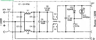
True, this is honestly shown in the Ripple Rejection diagram. Now - about the most unpleasant thing, namely the discrepancy between the actual electrical characteristics and the declared ones. This is a typical voltage regulator circuit with an output voltage of 12 V.
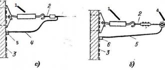
Recommendations for the use of protective diodes for LM are of a general theoretical nature and consider situations that do not occur in practice. The most effective way is to assemble a simple stand using a breadboard for testing and power everything from a battery. To do this, we include chains of transistors and resistors in the control circuit, as shown in the figure below.
The LM chip in the TO package is capable of operating stably at a maximum load current of up to 1.5 amperes. But the circuits and data in its datasheet are still the same... So, the shortcomings of LM as a microcircuit and errors in the recommendations for its use. It is also easy to make a source with several fixed voltages on this chip, which can be switched programmatically using a microcontroller. Pin configuration Typical LM connection circuit The circuit of an regulated power supply on the LM will look like this: Transformer power W, secondary winding voltage volts. Therefore, more than 5 volts must be applied to the Vin input.
Specifications:
These are maximum values that can damage the device or affect its stability. Which increases the level of ripple on the load with increasing frequency. And for LM, it actually means the degree of its own inferiority and shows how well LM fights the pulsations, which it itself takes from the exit and again drives inside itself. Then the circuit of our adjustable bipolar source may look like this: Here, additional powerful transistors VT1 and VT2 allow you to increase the output current of the stabilizers. In addition to the domestic integrated circuit KREN12, more powerful imported analogues are produced, the output currents of which are several times higher.
Stabilization is carried out by changing the resistance of one of the divider arms: the resistance is constantly maintained so that the voltage at the output of the stabilizer is within the established limits. Current stabilizer circuit on lm The advantage of this stabilizer is that it is linear and does not introduce high-frequency interference, for example, like some pulse stabilizers. Stabilization and protection of the circuit Capacitance C2 and diode D1 are optional. Analogues of lm Sometimes it is not possible to find the specifically required microcircuit on the market, then you can use similar ones. Since we want 5 volts output, we will supply 7 volts to the regulator.
This is quite often observed in the manufacture of powerful LED lamps. You can make your life easier if you use an LM chip - an analogue of an LM chip, but with a negative voltage. Which increases the level of ripple on the load with increasing frequency. Current stabilizer circuit on lm The advantage of this stabilizer is that it is linear and does not introduce high-frequency interference, for example, like some pulse stabilizers. Therefore, you don’t even have to redo the circuit of the finished device in order to adjust the parameters of the voltage regulator or unchangeable stabilizer. Power supply based on LM338T part 1
Typical LM317 circuits
As stated, the LM317 is used to create regulated and unregulated power supplies, however, it can also be used as the basis of a current regulator when creating LED drivers that maintain current in the circuit regardless of the input voltage. The applications described in the datasheet alone are enough to fill a separate book, so we will analyze several of the most popular circuits based on this stabilizer.
Adjustable power supply (1.2-37V)
All that is needed to create it is to replace R2 with a variable resistor, and also add a transformer with a diode bridge to the input. When using it, it is worth considering that the microcircuit has a reference voltage of 1.25V, so it will be minimal for this circuit.
Adjustable power supply (0-37V)
If you need full regulation from 0V, then circuit manufacturers suggest connecting a 10V negative voltage source to the circuit.
You can wind an additional coil on the power supply transformer and connect its leads after the diode bridge as follows:
Or you can use a negative voltage source that will be powered from the main winding.
Thus, you will get a simple laboratory power supply.
LED Driver (Current Stabilizer)
With this circuit you can power fairly powerful LEDs and LED strips. All you need is to know the current consumed and, based on it, select the resistance using the formula.
It uses the same principle as the simplest circuit, but instead of a resistive divider, a current sensor is installed. The more current the load consumes at the output, the greater the voltage drop will be observed across the sensor. It is monitored by the IC and it increases or decreases the voltage to maintain a stable current. Even in the event of a short circuit, the current will remain at the stable level that was set.
Charger
The circuit of this charger is taken from the datasheet and has an output voltage of 6V with a limit of 0.6A. By changing the resistance of resistors R1 and R2, it is possible to adjust the voltage to suit your needs, and with the help of resistor R3 - the current. It is suitable for powering batteries of phones, tools and household appliances.
AC voltage regulation
Since two LM317 can regulate not only positive, but also negative sine wave oscillations, they can be used to create an AC regulator. You can see that the circuit is quite simple and does not require many components:
Connection schemes
First, let's look at the standard circuit, which can be found in the technical documentation for the LM317T. In addition to the stabilizer itself, there are two capacitors on it, one of which is installed at the input (with a capacity of 0.1 mF), and the second at the output (1.0 mF). As well as two resistors R1 and R1.
As you can see, resistors R1 and R2 are connected to the control output of the device using a voltage divider circuit. Resistance R1 is constant and its value, according to the manufacturer’s recommendations, should be equal to 240 Ohms. Using R2 you can adjust the output voltage. It can be found using the formula:
The second term in it is small, since the value of IADJ cannot be longer than 100 mA, so it can be ignored in the calculations. From the formula it is clear that the greater the resistance R2, the greater the output voltage.
Let's calculate what voltage will be at the output if the value of resistance R2 is 1.5 kOhm.
As can be seen from the calculations, the output voltage will be 9 V. But in order to obtain this potential difference, a higher voltage must be applied to the input.
Often the task arises of finding R2 knowing the required stabilization voltage. To do this you can use the formula:
So that you don’t have to do the calculations manually, we present a table in which all the necessary values have already been calculated (resistance R1 = 240 Ohms).
| Stabilization voltage, V | Resistance value R2, Ohm | Nearest standard value, Ohm |
| 3 | 336 | 330 |
| 3,3 | 393,6 | 390 |
| 4,7 | 662,4 | 680 |
| 5 | 720 | 750 |
| 5,5 | 816 | 820 |
| 7,4 | 1180,8 | 1 200 |
| 9 | 1488 | 1 500 |
| 10 | 1680 | 1 600 |
| 12 | 2064 | 2 000 |
| 15 | 2640 | 2 700 |
| 18 | 3216 | 3 300 |
| 20 | 3600 | 3 600 |
| 25 | 4560 | 4 700 |
| 27 | 4900 | 5 100 |
It is easy to assemble a current driver on the LM317T. Typically, such circuits are used to power individual LEDs and LED arrays. Manufacturers recommend using the following scheme:
In this example, the output current through the LED is set by selecting resistance R1. It can be calculated using the formula:
where Iout is the current at the output of the stabilizer, which is equal to the current through the LED.
The typical current through a single low-power LED is 0.02 A. We substitute this value into the formula and get resistance R1 - 62.5 Ohms. To prevent the resistor from burning out, you need to determine its power. To do this we use the formula:
In our case, the resistor power should be greater than 0.022*62.5=0.024 W, that is, any resistor will do, even the smallest one.
After standard examples, let's move on to the real design. Let's consider an adjustable power supply, in which you can adjust the output voltage in the range from 1.2 to 30 V and designed for a maximum output current of 10 A. In this case, the power supply has short circuit protection.
This device is made from a minimum number of inexpensive parts. Since the LM317T stabilizer is capable of withstanding a current of no more than 1.5 A, the design uses the MJE13009 transistor, thanks to which a current of 10 A can be obtained at the output.
The output voltage is adjusted using a variable resistor P1 with a nominal value of 5 kOhm. In addition, the circuit uses shunt resistors R1 and R2 with the same resistance - 200 Ohms. After turning off the power, capacitor C1 is discharged through resistor R3 with a resistance of 10 kOhm. At the output of the transformer, the voltage can be from 12 to 35 V. You can take any diode bridge that can withstand a current of 10 A and above, for example, GBJ2510 rated at 25 A.
The MJE13009 transistor can be replaced with MJE13007 or domestic KT805, KT808, KT819 or others. When choosing a transistor, it is important to pay attention to the current strength at the output of the stabilized power supply.
The transistor and LM317T used must be installed on a radiator with an area large enough for cooling. For these purposes, you can use a computer processor cooling system. Don't forget to insulate the LM317T from the heatsink with a thermally conductive pad. It is also advisable to install a diode bridge on the radiator.
How to test LM317?
Unlike transistors, this microcircuit cannot be checked with a multimeter. This method does not in any way guarantee correct operation due to the large number of internal elements not connected to the terminals. Therefore, if one of them fails, then checking it with a multimeter will be problematic. The easiest way to test the operation of the LM317 is to create a simple stand on a breadboard, and it can be powered only by a battery.
This way, you can quickly verify that an item is in full working order, even if you need to check several pieces.
Application of LM317
The diagrams given above are only a small part, the basis, compared to what can be done with this stabilizer. It can be used in almost all circuits that require a constant power supply of up to 40 V. Here are some applications described in the official technical document of this chip:
- Personal computers
- Digital cameras
- ECG
- Internet switches
- Biometric sensors
- Electric motor drivers
- Portable chargers
- PoE
- RFID readers
- Appliances
- X-ray machines
As you can see, even the manufacturer himself expects the widest possible use of this element, to say nothing of home-made manufacturers who are ready to present the most unusual circuits using LM317.
A simple two-polar voltage regulator on LM317.
The device is based on the circuit described above, and a negative voltage stabilization arm is added.
Characteristics and advantages of a two-polar stabilizer
- stabilization voltage from 1.2 to 30 V;
- maximum current up to 5 A;
- a small number of elements are used;
- simplicity in choosing a transformer, since you can use the secondary winding without a central tap;
The parts are installed on one-sided fiberglass. Transistor VT1, VT2 and microcircuits LM317 and LM337 should be installed on radiators. When installing on a common radiator, insulating gaskets and bushings should be used.
Increasing the maximum output current
There are two ways to increase the maximum output current. If you need to get more than 1.5A, then you can either connect several chips in parallel, or connect a power transistor.
In the first case, it is enough to connect resistors with low resistance to the output of the stabilizers. They are needed to equalize currents.
However, it is not always rational to use several chips. Therefore, a transistor comes to our aid. In this case, it will be enough to add it and a resistor as a harness to it.
If the load draws a small current, it will pass through the chip without affecting the transistor. And when it increases, almost all the current will pass through the transistor, leaving a small part of it for the stabilizer. But when using this circuit, there is internal protection inside the LM317 from short circuit.
Analogs LM317
What to do if it is not possible to use LM317? You can use its analogues. The twin brothers of this component are UPC317, GL317, ECG1900 and SG317. The domestic analogue is KP142EH12A, and there is also a KP142EN12 with a fixed voltage.
If the LM317 is not enough power for your project, then you can use more powerful options:
- LM350AT and LM350T – maximum output current 3A and power 25W
- LM350K – current 3 A and power 30 W
- LM338T and LM338K – current 5 A
All these microcircuits have the same pins, so the circuits do not have to be changed in any way.
Safe operation of LM317
It is worth remembering the operational characteristics of the radio component and not using it in critical conditions. The power dissipation according to official information is 20 W, and the difference between the input and output voltages should not exceed 40 V. During soldering, the temperature should not exceed 260 C. It can be used at temperatures from 0C to 125C, and stored from -65C to 150C. All these are officially declared characteristics; in reality, they may differ from instance to instance and be underestimated.
You should not use the element at the maximum and minimum indicated values. With such operation, the level of stability and reliability will drop significantly. It is also highly advisable to use a radiator to remove heat, since otherwise the stated characteristics may not coincide with the real ones.