Serial numbers should be assigned to elements, starting with one, within a group of elements that are assigned the same letter position designation in the diagram, for example, Q1, Q2, Q3, in accordance with the sequence of their location on the diagram from top to bottom and from left to right. Positional designations are placed next to the symbolic graphic designations of the elements on the right side or below them.
When depicting an element on the diagram in an “exploded” way, the positional designation of the element is placed next to each component.
The schematic diagram must clearly identify all the elements included in the installation and shown in the diagram. When performing a diagram on incomplete sheets, the following requirements must be met:
— the numbering of positional designations of elements must be continuous within the installation;
— the list of elements must be general;
- when repeating individual elements on other sheets of the diagram, the positional designations assigned to them on one of the first sheets of the diagram should be protected.
Introduction
But let's start a little from afar... Every young specialist who comes to design begins either by folding drawings, or by reading regulatory documentation, or by drawing “this” according to this example. In general, normative literature is studied in the course of work and design.
It is impossible to read all the normative literature related to your specialty or even a narrower specialization. Moreover, GOST, SNiP and other standards are periodically updated. And each designer has to monitor changes and new requirements of regulatory documents, changes in the lines of electrical equipment manufacturers, and constantly maintain their qualifications at the proper level.
Remember Lewis Carroll in Alice in Wonderland?
“You have to run as fast as you can just to stay in place, and to get somewhere, you have to run at least twice as fast!”
This is not my way of whining about “how hard the life of a designer is” or boasting “look, what an interesting job we have.” That's not what we're talking about now. Given such circumstances, designers adopt practical experience from more experienced colleagues; they simply know how to do many things correctly, but do not know why. They work according to the principle “That’s the way it is here.”
Sometimes these are quite basic things. You know how to do it right, but if they ask “Why is this?”, you won’t be able to answer right away, referring at least to the name of the regulatory document.
In this article, I decided to structure the information regarding symbols, sort everything out, and collect everything in one place.
Connection group table
The table below shows the designations of the connection groups and the phase rotation of the low and high sides.
| Connection group | Designation | Phase rotation |
| 0 | Y/Y-0 | C, B, A |
| c, b, a | ||
| ∆/∆-0 | C, B, A | |
| c, b, a | ||
| 1 | Y/∆-1 | C, B, A |
| c, b, a | ||
| ∆/Y-1 | C, B, A | |
| c, b, a | ||
| 2 | Y/Y-2 | C, B, A |
| c, b, a | ||
| ∆/∆-2 | C, B, A | |
| a, c, b | ||
| 3 | Y/∆-3 | C, B, A |
| b, a, c | ||
| ∆/Y-3 | C, B, A | |
| b, a, c | ||
| 4 | Y/Y-4 | C, B, A |
| b, a, c | ||
| ∆/∆-4 | C, B, A | |
| b, a, c | ||
| 5 | Y/∆-5 | C, B, A |
| c, b, a | ||
| ∆/Y-5 | C, B, A | |
| c, b, a | ||
| 6 | Y/Y-6 | C, B, A |
| c, b, a | ||
| ∆/∆-6 | C, B, A | |
| c, b, a | ||
| 7 | Y/∆-7 | C, B, A |
| c, b, a | ||
| ∆/Y-7 | C, B, A | |
| c, b, a | ||
| 8 | Y/Y-8 | C, B, A |
| a, c, b | ||
| ∆/∆-8 | C, B, A | |
| c, b, a | ||
| 9 | Y/∆-9 | C, B, A |
| b, a, c | ||
| ∆/Y-9 | C, B, A | |
| b, a, c | ||
| 10 | Y/Y-10 | C, B, A |
| c, b, a | ||
| ∆/∆-10 | C, B, A | |
| b, a, c | ||
| 11 | Y/∆-11 | C, B, A |
| c, b, a | ||
| ∆/Y-11 | C, B, A | |
| c, b, a |
Types and types of electrical circuits
Before talking about symbols on diagrams, you need to understand what types and types of diagrams there are. On July 1, 2009, GOST 2.701-2008 “ESKD. Scheme. Types and types. General requirements for implementation." In accordance with this GOST, schemes are divided into 10 types:
- Electric scheme
- Hydraulic circuit
- Pneumatic circuit
- Gas circuit
- Kinematic scheme
- Vacuum circuit
- Optical circuit
- Energy scheme
- Division scheme
- Combined scheme
Types of schemes are divided into eight types:
- Structural diagram
- Functional diagram
- Schematic diagram (complete)
- Connection diagram (installation)
- Connection diagram
- General scheme
- Layout diagram
- Combined scheme
As an electrician, I am interested in circuits of the “Electrical circuit” type. In general, the description and requirements for circuits are given in GOST 2.701-2008 using the example of electrical circuits, but since January 1, 2012 GOST 2.702-2011 “ESKD. Rules for the execution of electrical circuits." For the most part, the text of this GOST duplicates the text of GOST 2.701-2008, and other GOSTs also refer to it.
GOST 2.702-2011 describes in detail the requirements for each type of electrical circuit. When making electrical circuits, you should be guided by this GOST.
GOST 2.702-2011 gives the following definition of the concept of an electrical circuit: “An electrical circuit is a document containing, in the form of conventional images or symbols, the components of a product operating with the help of electrical energy, and their interconnections.” Next, GOST refers to documents regulating the rules for the implementation of conventional graphic images, letter symbols and designations of wires and contact connections of electrical elements. Let's look at each separately.
Toroidal transformers
The industry also produces so-called toroidal transformers. One of these is shown in the photo:
Photo – toroidal transformer
The advantages of such transformers compared to conventional transformers are higher efficiency, less iron sound chatter during operation, low stray field values, and smaller size and weight.
Transformer cores, depending on the design, can be different; they are made from plates of soft magnetic material; the figure below shows examples of cores:
Transformer cores - drawing
Here, in brief, is all the basic information about transformers in radio electronics; various special cases can be considered in more detail on the forum. Author AKV .
Graphic symbols in electrical diagrams
Regarding graphic symbols in electrical circuits, GOST 2.702-2011 refers to three other GOSTs:
- GOST 2.709-89 “ESKD. Conventional designations of wires and contact connections of electrical elements, equipment and sections of circuits in electrical circuits.”
- GOST 2.721-74 “ESKD. Conditional graphic designations in schemes. Designations for general use"
- GOST 2.755-87 “ESKD. Conventional graphic symbols in electrical diagrams. Switching and contact connection devices."
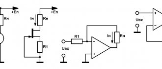
Conventional graphic symbols (UGO) of automatic circuit breakers, switches, contactors, thermal relays and other switching equipment that is used in single-line diagrams of electrical panels are defined in GOST 2.755-87.
However, there is no designation for RCDs and difavtomats in GOST. I think it will soon be reissued and the RCD designation will be added. In the meantime, each designer depicts an RCD according to his own taste, especially since GOST 2.702-2011 provides for this. It is enough to provide the UGO designation and its explanation in the explanations of the diagram.
In addition to GOST 2.755-87, to complete the circuit, you will need to use images from GOST 2.721-74 (mainly for secondary circuits).
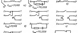
All designations of switching devices are based on four basic images:
using nine functional features:
| Name | Image |
| 1. Contactor function | |
| 2. Switch function | |
| 3.Disconnector function | |
| 4. Switch-disconnector function | |
| 5. Automatic triggering | |
| 6. Travel or limit switch function | |
| 7. Self-return | |
| 8. No self-return | |
| 9. Arc suppression | |
| Note: The designations given in paragraphs. 1 - 4, 7 - 9, are placed on fixed contacts, and the designations in paragraphs. 5 and 6 - on moving contacts. | |
Basic graphic symbols used in single-line diagrams of electrical panels:
| Name | Image |
| Circuit breaker (automatic) | |
| Load switch (switch) | |
| Contactor contact | |
| Thermal relay | |
| RCD | |
| Differential automatic | |
| Fuse | |
| Automatic switch for motor protection (circuit breaker with built-in thermal relay) | |
| Load switch with fuse (switch with fuse) | |
| Current transformer | |
| Voltage transformer | |
| Electric energy meter | |
| A frequency converter | |
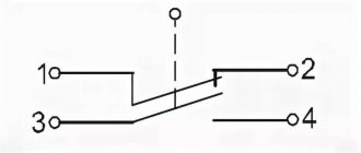
| Normally closed contact of a push-button switch without self-reset with the control element opening and returning automatically | |
| Normally closed contact of a push-button switch without self-reset with opening and return of the control element by pressing the button a second time | |
| Normally closed contact of a push-button switch without self-reset with opening and return of the control element by pulling the button | |
| Normally closed contact of a push-button switch without self-reset with opening and returning of the control element via a separate drive (for example, pressing a reset button) | |
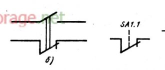
| Normally closed contact with delay when activated | |
| Normally closed contact with delay during return | |
| Normally closed contact with delay during operation and return | |
| Normally closed contact with delay when activated | |
| Normally closed contact with delay during return | |
| Normally closed contact with delay during operation and return | |
| Contactor coil, general designation for relay coil | |
| Impulse relay coil | |
| Photo relay coil | |
| Timing relay coil | |
| Motor drive | |
| Lighting lamp, light indication (light bulb) | |
| A heating element | |
| Plug connection (socket): socket pin | |
| Arrester | |
| Surge suppressor (SPD), varistor | |
| Dismountable connection (terminal) | |
| Ammeter | |
| Voltmeter | |
| Wattmeter | |
| Frequency meter |
The designations of wires and busbars in electrical panels are determined by GOST 2.721-74.
| Name | Image |
| Electrical communication line, wires, cables, buses, group communication line | |
| The protective conductor (PE) may be shown as a dashed line | |
| Graphic branching (merging) of group communication lines | |
| Crossing of electrical communication lines, group communication lines of electrically not connected wires, cables, tires, not electrically connected | |
| Electrical communication line with one branch | |
| Electrical communication line with two branches | |
| Bus (if it is necessary to graphically separate electrical communication lines from the image) | |
| Branch bus | |
| Buses graphically intersecting and not electrically connected | |
| Branches (tap-offs) from the bus |
How vector diagrams are constructed
When constructing vector diagrams, you need to remember the rule that the phase shift between the phases is 1200, that is, if the voltages are equal, the ends of the vectors will always form an equilateral triangle.
The simplest diagram to draw is for a star connection. A point is placed in the center of the diagram, which corresponds to the combined ends of the windings. Phase vectors are drawn from the center at angles of 1200. The vector of the middle phase is drawn vertically.
For a triangle, draw a line parallel to the corresponding phase of the star, and from its ends, respectively, the remaining two phases are connected to it. The condition must be met - all sides of the triangle must be parallel to the corresponding phases of the star. The required vectors will be lines drawn from the center of the triangle to its vertices.
Vector diagrams are drawn for the high and low sides and then aligned with a single center. The angle between like phases will indicate the connection group number expressed in hours.
The count must be taken from the high voltage vector to the low one.
Letter designations in electrical diagrams
Letter designations are defined by GOST 2.710-81 “ESKD. Alphanumeric designations in electrical circuits.”
There are no designations for automatic devices and RCDs in this GOST. On various sites and forums on the Internet, they discussed for a long time how to correctly designate RCD and difavtomat. GOST 2.710-81 in clause 2.2.12. allows the use of multi-letter codes (and not just one- and two-letter codes), therefore, before the introduction of the regulatory designation, I adopted for myself the three-letter designation of the RCD and the difavtomat. I added the letter D to the two-letter designation of the switch and received the designation RCD. I did the same with the automatic rifle.
I think it will soon be reissued and the RCD designation will be added.
Designations of the main elements used in single-line diagrams of electrical panels:
| Name | Designation |
| Automatic switch in power circuits | QF |
| Automatic switch in control circuits | SF |
| Automatic switch with differential protection (difavtomat) | QFD |
| Load switch (switch) | QS |
| Residual current device (RCD) | QSD |
| Contactor | K.M. |
| Thermal relay | F, KK |
| Time relay | KT |
| Voltage relay | KV |
| Photo relay | KL |
| Impulse relay | KI |
| Arrester, arrester | F.V. |
| Fuse | F.U. |
| Current transformer | T.A. |
| Voltage transformer | TV |
| A frequency converter | UZ |
| Ammeter | PA |
| Voltmeter | PV |
| Wattmeter | PW |
| Frequency meter | PF |
| Active energy meter | P.I. |
| Reactive energy meter | PK |
| Photocell | B.L. |
| A heating element | E.K. |
| Lighting lamp | EL |
| Light indication device (light bulb) | H.L. |
| Plug connector (socket) | XS |
| Switch or switch in control circuits | S.A. |
| Push-button switch in control circuits | S.B. |
| Terminals | XT |
Welding transformers
There are special welding transformers.
The welding transformer is designed for electric arc welding; it works as a step-down transformer, reducing the voltage on the secondary winding to the required value for welding. The voltage of the secondary winding is no more than 80 Volts. Welding transformers are designed for short-term short circuits of the output of the secondary winding, in which an electric arc is formed, and the transformer does not fail, unlike a power transformer.
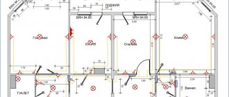
Representation of electrical equipment on plans
Although GOST 2.701-2008 and GOST 2.702-2011 provide for the type of electrical circuit “layout diagram”, when designing buildings and structures one should be guided by GOST 21.210-2014 “SPDS. Conventional graphic images of electrical equipment and wiring on plans.” This GOST establishes symbols for electrical wiring, busbar laying, busbars, cable lines, electrical equipment (transformers, electrical panels, sockets, switches, lamps) on plans for laying electrical networks.
These symbols are used when making drawings of electrical supply, power electrical equipment, electrical lighting and other drawings. Also, these designations are used to depict consumers in single-line circuit diagrams of electrical panels.
Conventional graphic images of electrical equipment, electrical devices and electrical receivers
| Name | Image |
| Electrical device. General image | |
| Electrical device, incl. with engine | |
| Device with generator | |
| Engine generator | |
| Complete transformer device with one transformer | |
| Complete transformer device with several transformers | |
| Complete condenser installation | |
| Complete converter installation | |
| Rechargeable battery | |
| Electric heating device. General designation |
Conventional graphic designations of wiring lines and conductors
| Name | Image |
| Wiring line, general image | |
| Wiring line indicating information (type of current, voltage, material, installation method, mark, etc.) | |
| Wiring line indicating the number of conductors (the number of conductors is indicated by serifs; if the number of conductors is more than three, numbers are used instead of serifs) | |
| Control line | |
| Line of emergency evacuation and security lighting networks | |
| Voltage line 36V and below | |
| Grounding and grounding line | |
| Grounding switches | |
| Open laying of wires and cables | |
| Rope gasket | |
| Gasket in tray | |
| Gasket in the box | |
| Gasket under the baseboard | |
| Gasket in pipe | |
| Release seal in pipes for hazardous areas | |
| Flexible wiring in a metal hose or flexible input | |
| Vertical gasket. The cable goes to a higher level or comes from a higher level | |
| Vertical gasket. The cable goes to a lower level or comes from a lower level | |
| Vertical gasket. The cable crosses the mark shown on the plan from top to bottom or bottom to top and has no horizontal sections within this plan |
Unfortunately, AutoCAD in the basic package does not contain all the necessary line types.
Designers solve this problem in different ways:
- most draw the wiring with a regular line, and then supplement it with symbols of circles, squares, etc.;
- Advanced AutoCAD users create their own linetypes.
I am a supporter of the second method, because... it's much more convenient. If you use a special type of line, then when you move it, all the “additional” symbols also move, because they are part of the line.
Creating your own linetype in AutoCAD is quite simple. You will spend some time mastering this skill, but you will save a lot of time later when designing.
It is most convenient to depict a vertical layout using AutoCAD blocks, or better yet, using dynamic blocks.
Conventional graphic images of tires and busbars
| Name | Image |
| Laying of busbars and busbars. General image | |
| Busbar laid on insulators | |
| Package of tires laid on insulators | |
| Busbars or busbar trunking on racks | |
| Busbars or busbar trunking on hangers | |
| Busbars or busbar trunking on brackets | |
| Trolley line | |
| Trolley line sectioning | |
| Tire compensator, trolley | |
| Note. The image of the mounting location of the busbar must correspond to its design position | |
It is convenient to draw buses and busbars in AutoCAD using polylines and/or dynamic blocks.
Conventional graphic images of boxes, cabinets, panels and consoles
| Name | Image |
| Branch box | |
| Introductory box | |
| Pull-out box, pull-out box | |
| Box, drawer with clamps | |
| Distribution cabinet | |
| Panel of group working lighting | |
| Group emergency lighting panel | |
| Laboratory shield | |
| Equipment box | |
| Control box | |
| Cabinet, panel, remote control, one-way service panel, local control station | |
| Cabinet, two-way service panel | |
| Cabinet, panel, remote control consisting of several panels for one-way operation | |
| Cabinet, panel, remote control consisting of several panels of two-way service | |
| Open shield | |
| Step-down transformer box (TSB) |
Rendering in AutoCAD is conveniently done using blocks and dynamic blocks.
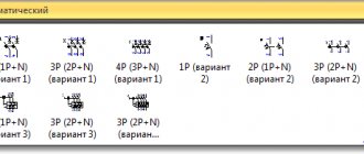
Conventional graphic symbols of switches, switches
GOST 21.210-2014 does not provide conventional images for dimmers and a separate image for push-button switches, so I introduced my own designations for them in accordance with clause 4.7.
| Name | Image |
| Switch for surface installation with degree of protection from IP20 to IP23 | |
| single-pole | |
| single pole double | |
| single-pole triple | |
| bipolar | |
| three-pole | |
| Switch for flush installation with degree of protection from IP20 to IP23 | |
| single-pole | |
| single pole double | |
| single-pole triple | |
| bipolar | |
| Switch for open installation with a degree of protection not lower than IP44 | |
| single-pole | |
| bipolar | |
| three-pole | |
| Two-way switch without zero position with degree of protection from IP20 to IP23 | |
| open installation | |
| hidden installation | |
| Two-way switch without zero position with a degree of protection not lower than IP44 | |
| Dimmer (dimmer) for open installation with degree of protection from IP20 to IP23 | |
| Dimmer (dimmer) for hidden installation with degree of protection from IP20 to IP23 | |
| Dimmer (dimmer) for open installation with a degree of protection not lower than IP44 | |
| Push-button switch for open installation with degree of protection from IP20 to IP23 | |
| Push-button switch for hidden installation with degree of protection from IP20 to IP23 | |
| Push-button switch for open installation with a degree of protection not lower than IP44 |
It is convenient to draw in AutoCAD using dynamic blocks. I made myself one dynamic block for all types of switches.
Conventional graphic symbols of plug sockets
| Name | Image |
| Surface-mounted socket with degree of protection from IP20 to IP23 | |
| bipolar | |
| bipolar double | |
| two-pole with protective contact | |
| two-pole double with protective contact | |
| three-pole with protective contact | |
| a block of several computer sockets (the number indicates the number of sockets in the block) | |
| block of several household sockets (the number indicates the number of sockets in the block) | |
| Concealed socket outlet with degree of protection from IP20 to IP23 | |
| bipolar | |
| bipolar double | |
| two-pole with protective contact | |
| two-pole double with protective contact | |
| three-pole with protective contact | |
| a block of several computer sockets (the number indicates the number of sockets in the block) | |
| block of several household sockets (the number indicates the number of sockets in the block) | |
| Plug socket with a degree of protection of at least IP44 | |
| bipolar | |
| bipolar double | |
| two-pole with protective contact | |
| two-pole double with protective contact | |
| three-pole with protective contact | |
| a block of several computer sockets (the number indicates the number of sockets in the block) | |
| block of several household sockets (the number indicates the number of sockets in the block) |
It is convenient to draw in AutoCAD using dynamic blocks. I made myself one dynamic block for all types of sockets.
Conventional graphic symbols of lamps and spotlights
I am glad that the updated version of GOST has added images of LED lamps and lamps with compact fluorescent lamps.
| Name | Image |
| Lamp with incandescent lamp, halogen lamp | |
| Luminaire with compact fluorescent lamps | |
| LED lamp with a shape other than linear | |
| Lamp with linear fluorescent lamps (can also be shown to scale in the drawing) | |
| Linear LED lamp (can also be shown to scale in the drawing) | |
| Luminaire with high pressure discharge lamp | |
| Chandelier | |
| Slot light guide lamp | |
| Spotlight. General image | |
| A group of spotlights with the optical axis directed in one direction | |
| A group of spotlights with the optical axis directed in all directions | |
| Signal traffic light (three lamps) | |
| Wall lamp socket | |
| Suspended lamp socket | |
| Ceiling lamp socket | |
| Emergency lighting luminaire (example of a luminaire with an incandescent lamp) | |
| Lamp for special lighting (light indicator) |
It is convenient to draw lamps in AutoCAD using dynamic blocks.
Conventional graphic symbols of monitoring and control devices
| Name | Image |
| Call | |
| Siren, horn, howler | |
| Personnel call board for one signal | |
| Panel for calling personnel on several signals | |
| Advertising inscriptions and signs | |
| Starting device for electric motors. General image | |
| Magnetic switch | |
| Push-button post | |
| one button | |
| two buttons | |
| three buttons | |
| with two illuminated buttons | |
| two buttons with two signal lamps |
It is convenient to draw in AutoCAD using dynamic blocks.
Subscribe and receive notifications of new articles by e-mail
Transformer operating principle
Transformation coefficient - formula
If the transformation ratio is less than one, then the transformer is step-up, if it is more than one, then the transformer is step-down. Let's look at a small example: w1 the number of turns of the primary winding is equal to 300, w2 the number of turns of the secondary winding is 20. Divide 300 by 20, we get 15. The number is greater than one, which means the transformer is a step-down. Let's say we wound a transformer from 220 volts to a lower voltage, and now we need to calculate what the voltage will be on the secondary winding. We substitute the numbers: U2 = U1kt = 22015 = 14.66 volts. The output voltage from the secondary winding will be 14.66 volts.
Examples of group winding connections
The state standard provides only two groups of winding connections:
- Y/Y-0 or ∆/∆-0
- Y/∆-11 and ∆/Y-11
Strict standardization eliminates accidents and damage resulting from incorrect connections. In addition, for transformers of the same power and transformation ratio, parallel connection of devices becomes possible.
The remaining number of connections is used extremely rarely in some cases when it is impossible to use the standard option.
The type of connection must be specified in the accompanying documentation and duplicated on the device nameplate.
Determination of device currents
When determining the primary winding current, losses should be taken into account, as well as the magnetizing current of the transformer, the relative magnitude of which in low-power power transformers is very significant. The current values can be determined using the following formula:
It will be interesting➡ What is a transformer substation
where U1 and U2 are the voltages of the windings as specified;
P2 – power of the secondary winding as specified;
cos φ2 – load power factor according to the specification;
η – coefficient of performance (efficiency) of the transformer.
The choice of induction in the core rod and current density in the wires of the transformer windings - the permissible value of induction in the rod and yoke of the transformer core is determined by the selected value of the magnetizing current, power, frequency, type of transformer, number of joints in the core and the material of the latter.
You can read the article in more detail about the design of power transformers.
Areas of use
Autotransformers still occupy a strong position in various fields related to electrical engineering. Can't do without them:
- various rectifiers;
- radio engineering devices;
- telephone sets;
- welders;
- railway electrification systems and many other devices.
Three-phase autotransformers are used in high-voltage electrical networks. Their use increases the efficiency of power systems, which affects the reduction of costs associated with the transmission of electricity.
Electrical device design
Transformation of three-phase current does not necessarily imply the use of one transformer having a common magnetic circuit. Although such installations are widely used in the national economy.
There is the possibility of such a transformation using three separate single-phase transformers that are not magnetically connected to each other, that is, each individual phase will have its own separate magnetic circuit.
A transformer made according to this scheme is called a group transformer. The primary and secondary windings of the device are interfaced with each other according to one of the schemes adopted for transforming three-phase current.
Structurally, a three-phase transformer is a three-rod magnetic circuit with windings located on each of the rods, made in the same way as for single-phase devices.
Interesting material on the topic: how a toroidal transformer works.
Let's imagine three single-phase transformers placed next to each other so that their three rods form one common central rod. On each of the other three rods there are primary and secondary windings.
The currents in the transformer coils will create time-varying magnetic fluxes, which will each be closed in its own magnetic circuit. In the central composite rod, the magnetic fluxes will add up and give a total of zero, because these fluxes are created by symmetrical three-phase currents, regarding which we know that the sum of their instantaneous values is equal to zero at any moment of time.
Let us assume that the primary coils of all transformer bars are exactly the same and wound in the same direction. We connect all the upper ends of the coils to neutral O, and connect the lower ends of the coils to the three terminals of the three-phase network. The magnetic cores are made of sheet electrical steel. To weaken eddy currents and reduce magnetization reversal losses, steel sheets are insulated with varnish before assembly.
Detailed design of a three-phase transformer.
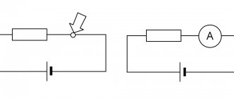
Determination by galvanometer method
There are several ways to determine whether the windings are connected correctly. The easiest way is to use a magnetoelectric system voltmeter. It is also called the direct current method.
To do this, a measuring device is connected to the ends of the winding being tested, and a constant voltage is applied to the other winding. The deflection of the arrow at the moment the key is closed will indicate the polarity of the winding connection. Such actions are performed for each winding.
You can also use a simple voltmeter when connecting AC voltage. To do this, a reduced alternating voltage is supplied to one of the windings, and the remaining two windings are connected in series and connected to a voltmeter. Absence or too small readings indicate that the windings are connected in opposite directions.