Electric machine
- an electromechanical converter that converts mechanical energy into electrical energy (generator), or electrical energy into mechanical energy (electric motor), or electrical energy with one parameters (voltage, frequency, etc.) into electrical energy with other parameters.
Both magnetic and electric fields can be used as an energy carrier in an electric machine. Machines that use a magnetic field to convert energy are called inductive, while those that use an electric field are called capacitive. It is also possible to use magnetic and electric fields together. Such machines are called inductive-capacitive.
In practice, inductive machines are most widely used.
It is customary to distinguish electromechanical converters depending on the purpose of energy conversion into:
- generators
- sources of electrical energy; - electric motors
are sources of mechanical energy; - special electrical machines - electromechanical converters with more complex purposes
Application areas of electrical machines
Modern electric machines have a wide variety of designs and can implement different types of voltage and current, as well as different types of motion - rotational, oscillatory, linear, etc. The power range of modern electric machines is 10-17 - 109 W. Figure 1 shows the distribution areas and areas of use of capacitive (graph 1), inductive-capacitive (graph 2) and inductive (graph 3) electrical machines. An electric machine is a very economical energy converter.
Figure 1 – Areas of distribution of electrical machines
To control modern electrical machines, complex electronic systems are used, which are structurally combined with an electromechanical converter and form the so-called electromechanotronic system, which acts as a single technical complex. All this significantly expands the functionality of electric machines and ensures their widespread implementation in all spheres of industrial and household activities of mankind [1].
DESIGN AND MANUFACTURE OF WINDINGS
Electrical machines
In modern electric machines, cylindrical opposite-pole (drum) windings are most widespread. The conductors of such windings are located along the air gap of the machine and do not cover the magnetic circuits of the stator and rotor. Other types of windings are found only in some special types of electrical machines [6].
TYPES OF WINDINGS AND THEIR INSULATION
Windings can be concentrated or distributed. In lumped windings, the turns that form a pole are combined into one, usually multi-turn coil, which is mounted on a ferromagnetic core. The pole formed by the coil and cores is called salient.
The concentrated windings of the poles of direct and alternating current machines are identical in connection diagrams and differ from each other only in the design features and methods of fastening the coils. The field windings of almost all DC machines are concentrated. In AC machines, the excitation windings of synchronous machines with a rotation speed of no more than 1500 rpm are lumped. Such machines are called machines with salient poles on the rotor or machines with salient pole rotors (Fig. 3.1).
Rice. 3.1. rotors of synchronous machines with salient poles:
A -
multi-pole;
b -
four-pole
Distributed windings consist of coils with a relatively small number of turns each (in high-power machines - up to one or two turns per coil). The coils are placed evenly along the entire circumference of the air gap in the slots of the stator or rotor (Fig. 3.2). The coils connected to each other according to a certain pattern form the so-called implicit poles of the machine.
Rice. 3.2. AC machine stator Fig. 3.3. Distributed coils
with distributed rectangular wire winding:
A -
subdivided;
b
- solid;
1
— groove parts;
2 —
frontal parts;
3
- output ends
Distributed windings are used in the stators and phase rotors of asynchronous machines, in the stators of synchronous machines, armatures of DC machines and in the rotors of synchronous machines with a rotation speed of 3000 rpm (in non-salient pole rotors). In a number of designs of DC machines, the excitation windings are also distributed.
The distributed winding coils (Fig. 3.3) are wound with winding wire. The straight parts of the turns located in the grooves of the magnetic circuit are called groove parts; curved ones, which connect the grooved parts to each other - with the frontal parts of the coil. Similar names - groove and frontal parts - have the corresponding parts of the reel. The bending areas of the frontal parts are called the heads of the coils, the beginnings and ends of the winding wire with which the coil is wound are called the output ends of the coil.
The sides of the coils of distributed windings can occupy either a whole slot or only half (Fig. 3.4). In the first case, the winding is called single-layer, in the second - two-layer, since the sides of the coils are placed in grooves in two layers: one in the lower half of the groove - the lower layer, the second in the upper half - the upper layer.
| Rice. 3.4. Cross-section of semi-closed stator slots with a round wire winding: a - low-power machines, single-layer winding; b - medium power machines, two-layer winding | Rice. 3.5. Schematic representation of the elements of coil windings: a - loop; b - wave, rod winding; c - loop; g - wave |
Some types of windings are made not from coils, but from rods - rod winding (Fig. 3.5). Each rod is like a coil, cut in half along the frontal parts, and consists of one groove and two halves of different frontal parts. The turns of the rod winding are formed after the winding is laid in the grooves and the heads of the rods are connected to each other. In calculations and diagrams, the rod winding is considered as a coil winding with one turn in the coil.
Based on the direction of bending of the frontal parts of the coils or rods, which determines the sequence of their connections to each other, loop and wave windings are distinguished (see Fig. 3.5).
Almost all windings of electrical machines are wound with insulated winding wire. Much less often, uninsulated rectangular wire or copper bars are used for windings, onto which insulation is applied during the manufacturing process of the coils. Only the short-circuited windings of the rotors of asynchronous motors and the damper or starting windings of synchronous machines do not have insulation. The rods of these windings are installed in non-insulated grooves of the magnetic circuit, and in most asynchronous motors with power up to 300...400 kW they are performed by pouring aluminum or its alloys into the grooves.
A number of requirements are imposed on the insulation of electrical machines, the purpose of which is to ensure reliable operation of the machine throughout its entire design life. The insulation, first of all, must have sufficient electrical strength to prevent possible short-circuiting of the winding turns to metal parts of the machine or to each other. To meet this requirement, the insulation must have good thermal conductivity, since otherwise the heat generated in the winding conductors will heat it above permissible limits, and the electrical strength of the insulation will be reduced. In addition, the insulation of the windings should not noticeably deteriorate its electrical properties under the influence of mechanical forces to which it is exposed during the process of laying the windings in the grooves, as well as during operation of the machine, under the influence of moisture, oil vapors and various gases that the air surrounding the machine may contain. These requirements determine the thermal and mechanical strength, moisture and oil resistance, etc. required for insulation.
According to its functional purpose, winding insulation is divided into body insulation - external insulation of coils, isolating them from the walls of the grooves in the cores (slot insulation) and from other metal parts of the machine (insulation of the frontal parts of the coils); interphase, isolating the coils of each phase of the winding from other phases; turn, isolating each turn of the coil from other turns; conductor - insulation of each of the winding conductors. Each type of insulation has its own specific design and is subject to different requirements.
In general, the thickness and design of all types of insulation are determined by its functional purpose, the rated voltage level of the machine, its type and the operating conditions for which the machine is intended.
The housing insulation of the groove parts of the winding coils is subject to the most severe operating conditions. The limited dimensions of the groove lead to the need to perform groove insulation in the form of a thin and mechanically strong layer that meets all the above requirements for the insulation of electrical machines, i.e., electrical and mechanical strength, thermal conductivity, etc. Modern electrical insulating materials make it possible to perform groove insulation of machines with a nominal voltage up to 660 V with a thickness not exceeding a few tenths of a millimeter per side, and high rated voltage machines with a thickness not exceeding a few millimeters per side.
Body insulation can be either continuous or sleeve insulation by design. Continuous insulation is formed by wrapping the coil conductors along their entire length with a tape of insulating material, such as mica tape, glass tape, or glass mica tape. The tape is usually applied half-overlapping (full overlap) in several layers, the number of which depends on the rated voltage of the machine. In most cases of structures, after applying the tape, the insulation is impregnated with insulating compounds - varnishes or compounds to create a monolithic insulating layer and increase its thermal conductivity and mechanical strength.
Sleeve insulation is formed by wrapping the straight grooved parts of the coils with a wide sheet of insulating material, followed by hot rolling of the applied layers (soft sleeve) or hot rolling, crimping and baking (hard sleeve). Continuous tape insulation is applied to the curved frontal parts of sleeve-insulated coils.
Continuous and sleeve insulation is used for the windings of all machines with a voltage of 3000 V and above, in the armature windings of high-power DC machines, the rod wave windings of phase rotors of asynchronous motors, as well as in special machines, for example, moisture-resistant designs at any rated voltage.
The slotted parts of the windings of machines with voltages up to 600 V are insulated with boxes made of one or two layers of insulating material - film synthetic cardboard, electronite, imidoflex, etc. The slotted boxes are installed in the slots before laying the winding. They cannot serve as reliable housing insulation for the windings of higher voltage machines.
Examples of winding insulation are given in the description of specific winding designs.
Table 3.10. Insulation of coil windings of phase rotors of asynchronous motors with power up to 100 kW, heat resistance class B
| Winding part | Position in the picture | Material | Number of layers | Double-sided insulation thickness, mm | |||
| Name | Brand | Thickness, mm | in width | in height | in width | in height | |
| Pazovaya | Swelling of insulation due to varnish application | — | — | — | — | 0,1 | 0,1 |
| 1 | Glass tape | LES | 0,1 | 1 layer staggered | 0,2 | 0,2 | |
| Just one reel | — | — | — | — | 0,3 | 0,3 | |
| 2 | Fiberglass fabric | LSB | 0,2 | 0,4 | 0,6 | ||
| 3 | Flexible micanite | GFS | 0,2 | 0,4 | 0,6 | ||
| 4 | Fiberglass fabric | LSB | 0,2 | 0,4 | 0,6 | ||
| 5 | Fiberglass | ST | 0,5 | — | — | 0,5 | |
| 6 | Same | ST | 0,5 | — | — | 0,5 | |
| 7 | « | ST | 0,5 | — | — | 0,5 | |
| Laying tolerance | — | — | — | — | 0,5 | 0,8 | |
| Total per groove without wedge | — | — | — | — | 4,7 |
Continuation of Table 3.10
| Winding part | Position in the figure | Material | Number of layers | Double-sided insulation thickness, mm | ||||
| Name | Brand | Thickness, mm | in width | in height | in width | in height | ||
| Frontal | Middle coils in a coil group | 8 | Glass tape | LES | 0,2 | 1 full overlap layer | 0,8 | 0,8 |
| Outer coils in a coil group | 9 | Fiberglass fabric | LSB | 0,2 | 1 full overlap layer | 0,8 | 0,8 | |
| 10 | Glass tape | LES | 0,2 | 1 full overlap layer | 0,8 | 0,8 | ||
| Insulation thickness of outer coils | — | — | — | — | 1,6 | 1,6 |
Rod windings of phase rotors of asynchronous motors are used in machines with a power of more than 100 kW, and in some versions - starting with a power of 40...50 kW. The windings are made of rectangular busbar copper. The mechanical rigidity of the rods makes it possible to make the rotor slots semi-closed with a narrow slot, which helps improve the performance of the engines. The rods are inserted into the grooves from the end of the rotor, so only one front part of the rod is bent before installation. The second frontal part is bent after installing the rod in place in the groove [2].
The insulation design of the rotor rod windings is given in Table. 3.11. This table gives two values for the number of layers and insulation thickness depending on the voltage on the rotor slip rings, which is determined by the winding data of the machine.
Sleeves for rotor rods are made from micafolia, steklomicafolium or from sheet materials based on micafolia: micafolia, glass micafolia. Thermosetting varnishes are used as binders for the manufacture of cartridges. The frontal parts of the rods are insulated with tape materials. The electrically weak point in the insulation of rotor rods, as well as in the coil windings of stators with sleeve insulation, is the junction of two types of insulation - sleeve on the groove part and continuous on the front.
Table 3.11. Insulation of rod windings of phase rotors of asynchronous motors with a rotation axis height ≥ 280 mm
| Winding part | Position in the picture | Material | Voltage up to 750 V | Voltage up to 1200 V | ||||||||||
| Name, brand | Thickness, mm | Number of layers | Double-sided insulation thickness, mm | Number of layers | Double-sided insulation thickness, mm | |||||||||
| Heat resistance class | Heat resistance class | Heat resistance class | in width | in height | Heat resistance class | in width | in height | |||||||
| B | F | H | B | F and H | B | F and H | B | F and H | ||||||
| Pazovaya | 1 | Glass mica plastifolium IFG-B | Synthofolium - F | Synthofolium - H | 0,15 | 0,16 | 4.5* turns | 3.5 turns | 1,1 | 2,2 | 9.5* turns | 7.5 turns | 2,4 | 4,5 |
| Fiberglass fabric | ||||||||||||||
| 2 | LSB-105/120 | LSP-130/155 | LSK-155/180 | 0,15 | 0,3 | 0,3 | 0,3 | 0,3 | ||||||
| Fiberglass | ||||||||||||||
| 3 | ST | STEF-1 | STK | 0,5 | — | 0,5 | — | 0,5 | ||||||
| 4 | ST | STEF-1 | STK | 0,5 | — | 0,5 | — | 0,5 | ||||||
| 5 | ST | STEF-1 | STK | 0,5 | — | 0,5 | — | 0,5 | ||||||
| Tolerance for winding installation | — | — | 0,3 | 0,5 | — | — | 0,3 | 0,5 | ||||||
| Total insulation thickness in groove (without wedge) | — | 1,7 | 4,5 | — | — | 6,6 | ||||||||
| Frontal | 6 | Glass mica tape LS-PE-934-TP | Polyimide film 0.05 3 = 0.15 | 0,15 | 1 full overlap layer | 0,6 | 0,6 | 2 full overlap layers | 1,2 | 1,2 | ||||
| 7 | Glass tape LES | 0,1 | 1 full overlap layer | 0,4 | 0,4 | 2 full overlap layers | 0,8 | 0,8 | ||||||
| Total thickness of the rod insulation in the front part | 1,0 | 1,0 | 2,0 | 2,0 |
* Taking into account shrinkage of 15...20%
In order to increase the electrical strength of the insulation of this section, it is insulated with a gradual transition from sleeve to continuous insulation using the cone or reverse cone type.
The insulation of phase rotor rods for motors of some standard sizes is made of continuous strip material along the entire length of the rod, followed by crimping and baking of the insulation in hot presses.
Short-circuited windings. Squirrel-cage windings are widely used in the rotors of asynchronous motors. They are also used as dampers and starters in the rotors of synchronous machines.
Their main difference from all other windings of electrical machines is the lack of insulation between the groove part of the winding and the walls of the groove. The sometimes encountered phase-isolated and short-circuited windings of the rotors of special-design asynchronous machines are not considered here.
The short-circuited windings of the rotors of asynchronous motors are divided into two types according to design and manufacturing technology: welded and cast (Fig. 3.10).
Damper and starting windings of synchronous machines are made only of welded construction. In the vast majority of cases, the winding rods have a round cross-section and are placed in the grooves of the pole pieces.
The damper windings of synchronous motors are more powerful than synchronous generators, since they are used in the same way as starting ones. Generators have damper windings made of copper. In engines, brass is often used to improve starting characteristics.
Rice. 3.10. Squirrel cage rotors of asynchronous motors:
- with insert rods; - with cast winding;
1
- winding rods;
2
— closing rings;
3
- ventilation blades
GROOVE FILLING COEFFICIENT
The toothed zone is the most magnetically stressed section of the magnetic circuit; therefore, when designing machines, they strive to choose the smallest dimensions of the grooves that ensure the placement of the required number of conductors and insulation in them. The degree of use of the groove volume to accommodate winding copper is estimated by the groove filling coefficient with copper, which is the ratio of the total cross-sectional area of all conductors in the groove to the cross-sectional area of the groove “in the clear”:
, (3.1)
where q
el
is
the cross-sectional area of an elementary conductor;
n
el—number of elementary conductors in one effective one;
u
p is the number of effective conductors in the slot.
Factor k
m depends on the total amount of insulation in the groove, i.e. on the thickness of the body, turn and conductor insulation and the presence of various insulating spacers. As the insulation thickness increases, for example in machines with higher voltage ratings or when inferior insulating materials are used, the copper fill factor of the groove decreases. This leads to deterioration in the use of the groove space, and consequently, the entire tooth zone of the machine.
Average values for modern electrical machines, depending on the rated voltage and type of windings, are given in table. 3.12.
Table 3.12. Average values of groove fill factor with copper
| Winding type | Coefficient |
| Windings made of round wire with enamel insulation for voltages up to 660 V | 0,3 |
| Windings made of rectangular wire for a voltage of 3000 V (wire brand PSD) | 0,22…0,37 |
| Rectangular wire windings for voltage 6000 V | 0,14…0,25 |
For a machine with windings of rectangular wires, it can be calculated quite accurately, since during design the location of each conductor in the groove is determined in advance.
In round wire windings, the position of each conductor in the slot cannot be determined in advance. In addition, the density of conductors in the slot is not constant. It depends on the forces applied by the wrapper when compacting the conductors as they are laid in the grooves. Experience has established that with an excessively high packing density of round wires, the labor intensity of winding work unjustifiably increases, and the reliability of the winding sharply deteriorates due to the resulting mechanical damage to the conductor insulation.
The density of laying conductors in the grooves is estimated by the technological coefficient of filling with conductors of the insulation-free cross-sectional area of the groove:
. (3.2)
The numerator of this expression is the product of the area of the square described around an insulated elementary conductor with a diameter by the number of all elementary conductors in the groove, and the denominator is the cross-sectional area of the groove free from insulation, i.e., the area in which the winding conductors are located. The coefficient is usually called the slot fill factor. It characterizes only the manufacturability of laying a winding from a round wire, and not the extent to which the volume of the groove is used to accommodate the winding conductors. So, with the same winding density, it will be the same for the windings of machines with different thicknesses of slot or conductor insulation, with double-layer or single-layer windings, etc.
In modern electrical engineering, the density of the winding is sought to be in the range of 0.7...0.75, with lower values in machines with the number of poles equal to two.
It should be noted that an increase in the number of elementary conductors in one effective conductor, i.e., the use of a winding wire of a smaller diameter with the same effective conductor area, leads to a slight increase in the fill factor, and vice versa. This is explained by the fact that the thickness of the winding wire insulation remains constant with relatively large changes in the diameter of the round winding wires (see Appendix P3).
DIAGRAM ELEMENTS AND SYMBOLS
TERMINALS OF THREE-PHASE WINDINGS
The main element of the winding of an electric machine is the coil. Several series-connected turns, located in the same slots, are combined with each other by common body insulation, resulting in the formation of a winding coil. Each side of the coil is placed in one groove. If the entire groove is occupied by the side of only one coil (the sides of the coils are arranged in one layer), then the winding is called single-layer. If the sides of two coils are placed in each slot, one above the other, then the winding is called two-layer.
Several series connected in adjacent grooves form a coil group, which is a winding of a pole or a pair of poles of one of the phases of the machine. The number of coils in a coil group is denoted by q.
Since
q
coils are placed in adjacent slots, the same sides of these coils occupy
q
slots, forming the winding of the pole of one phase of the machine.
In one coil group, all coils can only be connected in series, since the EMF vectors of the coils located in different slots are shifted relative to each other by the slot angle, and when connected in parallel, large equalizing currents arise. Parallel connection of coils in one group is used in some windings of large two-pole turbogenerators.
Several interconnected coil groups form a winding phase. Coil groups in phase are connected in series, parallel or mixed, series-parallel. The number of coil groups in each phase depends on the number of poles and the type of winding. The number of parallel branches when connecting coil groups is determined when calculating the windings.
In most cases, the ends of the phases are not connected inside the machine, but all the beginnings and all ends of the phases are brought to the terminal box terminals, which allows the machines to be switched on to two mains voltages, connecting the phases in a star or triangle. The voltage per phase of the stator winding does not change.
| Image of a winding diagram. The order of connecting individual coils, coil groups and winding phases to each other is specified in the technical documentation in the form of a drawing, which is called a winding diagram. When drawing diagrams, a number of conventions are adopted: a drawing depicting a winding diagram is not drawn to scale and does not reflect any relationship between the dimensions of the machine and the winding and its parts; each coil is represented by one line, regardless of the number of turns in it and the elementary conductors in each effective conductor; all coils are depicted in the same plane, etc. | Rice. 3.11. End diagram of a single-layer concentric winding z = 24, 2р = 4, а = 1 |
There are several known ways of depicting circuits, of which the most widespread are the so-called expanded and end circuits. The end diagram is a kind of end view of the wound core (Fig. 3.11). It clearly shows the positions of the frontal parts of the coils, but there is not enough space to depict inter-coil and inter-group connections, which is inconvenient in complex circuits with several parallel branches.
Expanded diagrams represent a development of a stator or rotor with a winding and allow you to show all the connections between the winding elements - coils and coil groups.
Phase zone. The sides of the coils of one coil group are distributed in q
slots lying one behind the other.
In a symmetrical m-phase winding, at each pole division of such groups there will be m with q
slots in each.
Consequently, the sides of the coils belonging to the same phase are located at each pole division τ in grooves occupying the 1/mth part of it, or the [π D
/(2рm)
=
τ/m]th part of the gap circumference, called the phase zone. In the windings of three-phase machines built according to this principle, the phase zone occupies an arc of a circle containing an electrical angle τ/m = 180°/3 = 60°, therefore such windings are called windings with a 60-degree phase zone.
Sometimes windings are used in which m q
The grooves are located on two pole divisions. The phase zone of such windings occupies the 2τ/mth part of the circle, which corresponds to an electrical angle of 120° in three-phase machines. Such windings are called windings with a 120-degree phase zone.
Most three-phase general purpose machines use windings with a 60-degree phase zone. However, there are also machines with windings that have a 120-degree phase zone. For example, in multi-speed induction motors with a pole-switching winding, when switched on to a larger number of poles, the winding has a 60-degree phase zone, and when switched on to work with a smaller number of poles, it has a 120-degree phase zone.
The most common winding designs with a 60-degree phase zone are discussed below. Fundamentally, winding circuits with a 120-degree phase zone do not differ from those discussed below, however, when compiling them and calculating winding coefficients, it is necessary to take into account the features of this type of winding.
Designation of winding terminals of three-phase machines. Currently, there are two systems for designating the terminals of the windings of electrical machines. One of them, established by GOST 183-74, is retained for machines developed before 1987 and modernized. The terminals of the windings of these machines are designated by the letters of the Russian alphabet: stator windings - C, rotor windings of asynchronous motors - P, excitation windings of synchronous machines - I. The numbers after the letters indicate the beginnings and ends of the phases: the first phase is 1 and 4, respectively, the second phase is 2 and 5, third phases 3 and 6. In table. 3.13 shows the designations established by GOST 183-74 depending on the number of terminals and the winding connection diagram. Designations must be applied directly to the ends of the terminals: on cable lugs, bus ends or special crimps tightly fixed to the terminals.
Table 3.13. Designations of winding terminals for AC electrical machines developed before 1987 and being modernized (GOST 183 - 74)
| Name and connection diagram of the winding | Number of pins | Name of phase or output | Pin designation |
| Start | end | ||
| Stator winding: Open circuit | First phase | C1 | C4 |
| Second phase | C2 | C5 | |
| Third phase | C3 | C6 | |
| Star connection | 3 or 4 | First phase | C1 |
| Second phase | C2 | ||
| Third phase | C3 | ||
| Zero point | |||
| Delta connection | First conclusion | C1 | |
| Second conclusion | C2 | ||
| Third conclusion | C3 | ||
| Excitation winding (inductors) of synchronous machines | I1 | AND 2 | |
| Wound rotor winding of asynchronous motors | First phase | P1 | |
| Second phase | P2 | ||
| Third phase | P3 |
Continuation of the table. 3.13
| Name and connection diagram of the winding | Number of pins | Name of phase or output | Pin designation |
| Star circuit | First phase | P1 | |
| Second phase | P2 | ||
| Third phase | P3 |
Notes: 1. In the drawings of electrical circuits for connecting windings with 6 output ends (in the drawings on the free field of the diagram), it is allowed to use double designations (C1C6; C2C4; C3C5) when connecting phases in a triangle and triple designation (C4C5C6) for the star point (zero point) when connecting phases into a star.
2. The terminals of composite and sectional stator windings of machines should be designated by the same letters as simple windings, but with additional numbers in front of the letters. For example, the conclusions of the first winding (first section) of the first phase; beginning 1C1, end 1C4, conclusions of the second winding (section) of the first phase: beginning 2C1, end 2C4.
3. The contact rings of the rotor of asynchronous motors are also designated as the rotor winding terminals connected to them, and the arrangement of the rings should be in the order of the numbers indicated in the table, and ring 1, connected to terminal P1, should be the farthest from the rotor winding.
In small machines, in which alphanumeric designations are difficult due to lack of space, GOST allows the use of color designations (Table 3.14) with wires with multi-colored insulation, paints, etc.
Table 3.14. Color designation of stator winding terminals of three-phase alternating current machines
| Winding connection diagram | Number of pins | Name of phase or output | Pin color code | |
| Start | end | |||
| Open circuit | First phase | Yellow | Yellow with black | |
| Second phase | Green | Green with black | ||
| Third phase | Red | Red with black | ||
| Star | 3 or 4 | First phase | Yellow | — |
| Second phase | Green | — | ||
| Third phase | Red | — | ||
| Zero point | Black | — | ||
| Triangle | First conclusion | Yellow | — | |
| Second conclusion | Green | — | ||
| Third conclusion | Red | — |
For machines developed after January 1, 1987, a designation system for winding terminals has been established (GOST 26772-85), which complies with international standards. According to this system (Table 3.15), the conclusions are designated by letters of the Latin alphabet: the first phase of the stator winding - by the letter U ,
the second phase - the letter V
,
the third phase - the letter W
;
the rotor winding terminals according to the phases are marked with the letters K, L and M
;
synchronous
machines - letter F. The beginnings and ends of the phases are indicated respectively
by
the numbers 1 and 2
,
located after the letters. If there are intermediate terminals, they are designated by a letter defining the phase and subsequent numbers: 3, 4, etc.
Table 3.15. Designation of winding terminals for AC electrical machines developed after January 1, 1987 (GOST 26772-85)
| Name and connection diagram of the winding | Number of pins | Name of phase or output | Pin designation | |
| Start | end | |||
| Stator winding: | ||||
| open circuit | First phase | UI | U2 | |
| Second phase | V1 | V2 | ||
| Third phase | Wl | W2 | ||
| star connection | 3 or 4 | First phase | U | |
| Second phase | V | |||
| Third phase | W | |||
| Star point | N | |||
| triangle connection | First conclusion | U | ||
| Second conclusion | V | |||
| Third conclusion | W | |||
| sectional winding | First phase | U1 | U2 | |
| Conclusions from the first phase | U3 | U4 | ||
| Second phase | VI | V2 | ||
| Conclusions from the second phase | V3 | V4 | ||
| Third phase | WI | W2 | ||
| Conclusions from the third phase | W3 | W4 | ||
| split windings designed for series or parallel connection | — | First phase | U1 | U2 |
| U5 | U6 | |||
| Second phase | VI | V2 | ||
| V5 | V6 | |||
| Third phase | W1 | W2 | ||
| W5 | W6 | |||
| separate windings designed for series or parallel connection | _ | First phase | 1U1 | 1U2 |
| 2U1 | 2U2 | |||
| Second phase | 1V1 | 1V2 | ||
| 2VI | 2V2 | |||
| Third phase | IW1 | IW2 | ||
| 2WI | 2W2 | |||
| Winding of a phase rotor of an asynchronous motor: | ||||
| open circuit | First phase | KI | K2 | |
| Second phase | L1 | L2 | ||
| Third phase | Ml | M2 | ||
| star connection | 3 or 4 | First phase | TO | |
| Second phase | L | |||
| Third phase | M | |||
| Star point | Q | |||
| triangle connection | First conclusion | K | ||
| Second conclusion | L | |||
| Third conclusion | M | |||
| Excitation winding of synchronous machines | — | F1 | F2 |
The color designations of winding terminals for machines in which alphanumeric designations are difficult are kept the same as with the previous system
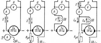
Fundamental laws of electromechanical energy conversion in inductive machines
Ampere's law
According to Ampere's law, a force acts on a current-carrying conductor in a magnetic field
- where F
– force, N, - I
– current strength, A, - – conductor length, m,
- B
—magnetic induction, T, - — angle between the direction of the current and the magnetic induction vector, degrees.
The direction of this force is determined by the “left hand” rule.
Faraday's law of electromagnetic induction
The discovery of electromagnetic induction in 1831 by Faraday is one of the fundamental discoveries in electrodynamics. Maxwell owns the following in-depth formulation of the law of electromagnetic induction:
Any change in the magnetic field over time excites an electric field in the surrounding space. The circulation of the strength vector E of this field along any fixed closed contour s is determined by the expression [3] [4]
,
- where E – electric field strength, V/m,
- ds – contour element, m,
- Ф - magnetic flux, Wb,
- t—time, s
The electromotive force of induction arising in a closed loop is equal to the rate of change in time of the flux of magnetic induction
,
- where is the electromotive force of induction, V
The “-” sign shows that the induced current arising in a closed conducting circuit has such a direction that the magnetic field it creates counteracts the change in the magnetic flux that caused the current.
content .. 11 12 15 ..SECTION 4
WINDINGS OF ELECTRICAL MACHINES
4.1. Types of windings of electrical machines
In electrical machines, the most common are cylindrical opposite-pole (drum) windings with a phase zone equal to the electrical angle tc/m. The conductors of this type of winding are located along the gap and are connected to each other in turns, without covering the magnetic circuit of the stator or rotor, as is the case in spiral or Gram windings.
A cylindrical winding of opposite poles can be concentrated or distributed. In a concentrated winding, the turns that form one pole are combined into one coil, usually multi-turn, located on salient poles (excitation windings of DC machines or synchronous machines with a salient pole rotor). Distributed windings consist of coils with a relatively small number of turns each, placed evenly along the circumference of the air gap in the grooves of the stator or rotor magnetic circuit.
The concentrated windings of AC and DC machines are identical in connection diagrams and differ only in design features. The distributed windings of AC machines differ from the distributed windings of DC machines (armature windings) both in connection diagrams and in the design of the windings themselves [2, 9, 18].
winding design
AC machines
Distributed windings of alternating current machines are divided into loop and wave - according to the direction of bending of the frontal parts and the connection sequence, and into single-layer and double-layer - according to the number of sides of the coils located in one groove.
The stator winding of m-phase electrical machines consists of t
parts called winding phases. In symmetrical windings, for example three-phase, all phases of the winding are the same, that is, they consist of the same number of turns and coils, symmetrically located in the magnetically conductive slots.
water and identically interconnected coil groups. The phases of the windings of single-phase and two-phase machines can be the same or differ in the number of turns, coils and cross-sectional area of the winding wire.
According to the design, windings made of round and rectangular wires are distinguished. The windings are called coil windings if the turns of each coil are formed by a continuous wire, or rod windings if the winding consists of individual rods, and the turns are formed only after they are laid in grooves by connecting the rods in their frontal parts.
Coil windings in AC machines are made only as loop windings. Rod windings, depending on the direction of bending of the frontal parts, can be loop or wave. This or that design of the windings is determined by the type and power of the machine, the rated voltage and the requirements for their insulation.
Round wire windings (loose)
placed in semi-closed slots of the stator (Fig. 4.1) or rotor. The design of winding insulation made of round wire (a groove box installed in the grooves before laying the winding) is not designed for high voltages, therefore such a winding is used only in machines with a rated voltage not exceeding 660 V. The low rigidity of the frontal parts of the winding cannot withstand dynamic loads, arising during start-up at high currents in the conductors, therefore round wire windings are not used in machines with a power of more than 100 kW.
For random windings, wires with a diameter of no more than 1.8 mm are used. If it is necessary to increase the cross-section of effective conductors, the winding is wound simultaneously from several parallel wires, called elementary. In this case, the cross-sectional area of the effective conductor is
9ef = “e9e.
where _
— the number of elementary conductors in one effective one;
q3
is the cross-sectional area of an elementary conductor. The density of laying conductors in the grooves is determined by the technological coefficient
Rice. 4.1. Examples of filling stator slots with round wire winding conductors
and insulation:
A -
single layer winding;
b -
two-layer winding of the machine with
h <
250 mm;
c
- two-layer winding of the machine with
h >
280 mm;
/ - winding conductors; 2 -
body insulation (slot box);
3 -
groove cover;
4 -
spacer between layers;
5 - groove wedge; 6 —
gasket under the wedge; 7 - gasket on
groove bottom
groove filling volume:
TO
= d|,H3«3″n/Sn,
where <1Eyu -
diameter of an insulated elementary conductor;
ip is the number of effective conductors in the slot; S^ is
the cross-sectional area of the groove free from insulation.
Typical values of the duty cycle k3
= 0.68 -t- 0.75.
Coefficient k3,
characterizing the density of conductors in a groove does not allow us to judge the efficiency of using the entire volume of the groove to place copper conductors in it. This factor takes into account the coefficient of filling the groove with copper:
kz,m
= ?ePe«p/5p,
where Sn is the total cross-sectional area of the groove.
With modern materials and brands of winding wires for round wire windings it is possible to achieve km = =
0.3 -g- 0.4 (higher values in single-layer windings with thinner housing insulation in the groove).
Rectangular winding wire windings
used in all machines with a rated voltage of 3000 V and above, in machines with a power of more than 100 kW and in some special machines with increased insulation requirements. For windings, use a wire with a cross-section of no more than 17 - 20 mm2. At high rated currents of machines, the efficiency
The effective conductors of the windings are formed from several elementary conductors of the specified cross-section.
Coils of rectangular wire are made either solid or subdivided (Fig. 4.2). Subdivided coils are those that are divided lengthwise into two identical structurally independent parts. They are placed in the slots of the machine one by one, and after laying, each pair is connected in parallel to each other. The accepted sequence and design of the coils make it possible to lay a winding of this type in half-open slots (Fig. 4.3, a), the slot of which is narrower than the width of the solid coil.
Low electrical strength of the housing insulation of a winding made of subdivided coils having the same design.
Rice. 4.2. Rectangular wire spools:
A -
subdivided;
b -
solid
Rice. 4.3. Examples of filling stator slots
rectangular winding conductors
wires and insulation:
A
- half-open stator slots with conductors of subdivided coils;
b -
open slots of the stator of a machine with a rated voltage of 6 kV;
/ - winding conductors; 2
- enveloping coating (for fastening conductors);
3 —
fastening tape:
4 —
body insulation (groove box);
5 — gasket on the bottom of the groove; b -
gasket between winding layers;
7 — gasket under the wedge; 8
— groove wedge;
9—
winding conductors with additional turn insulation;
10 —
sleeve body insulation;
11 -
external protective tape
as in random windings, it does not allow the use of a winding of this type in machines with a rated voltage above 660 V.
Solid coils of rectangular wire are usually insulated before laying, so they can only be laid in open slots (Fig. 4.3,6). The body insulation of the coils can be continuous along the entire length, made of tape insulating material, or sleeve insulation in the groove and continuous in the frontal parts. Both designs are widely used in modern electric machines.
At a voltage of more than 6 kV, a semiconducting coating is applied to the outer surface of the winding coils, which serves to prevent the corona phenomenon that occurs on the surface of the coils in places where the electric field strength is concentrated, for example, in places where the straight part of the coils exits the grooves.
Core winding
used in stators of large electrical machines, for example, in turbogenerators and hydrogenerators, as well as in phase rotors of asynchronous motors with a power of more than 50-60 kW.
To reduce losses from eddy currents, the stator winding rods are made from a large number of parallel elementary conductors with a cross-sectional area of 17 - 20 mm2, which, to reduce the effect of current displacement, are intertwined with each other in a certain way - transposed (Fig. 4.4). The design of the housing insulation of the rods is the same as that of the rectangular wire coils of high voltage rated machines.
The winding rods of phase rotors of asynchronous motors are made of rectangular copper wires with a large cross-sectional area. In the groove part, the winding rods are fastened with groove wedges, in the frontal parts - with wire bands or fiberglass bands.
Short-circuited windings
They are used as main ones in the rotors of asynchronous motors and as starting or damping ones in synchronous machines.
The short-circuited windings of the rotors of asynchronous motors are made either by filling the grooves with aluminum or its alloys, or from rods. Cast windings are used in the vast majority of rotors of asynchronous motors with power up to several hundred kilowatts. Simultaneously with the pouring of the rods, the closing rings of the winding with ventilation blades are cast. Manufacturing the rotor winding using the casting method allows you to make rotor rods of almost any desired configuration.
Rice. 4.4. Transposed stator winding rod:
A
— rod without body insulation;
b -
position of the rods in the stator groove
Rice. 4.5. Slots of squirrel-cage rotors with cast windings:
A -
unicellular;
6
- two-celled;
c -
with an uneven toothed zone (with alternating
grooves)
radios, including double cages with complex cross-sectional profiles of each of the rods or with alternating grooves (Fig. 4.5).
In most cases, copper is used for the winding of inserted rods; in double-cage rotors, copper is used for the working winding, and brass is used for the starting winding, which has greater resistance and heat capacity than copper, which is especially important in engines designed to operate under severe starting conditions.
In some series of asynchronous motors, for example ANZ, the short-circuited winding of the rotors is made of aluminum rods of rectangular cross-section, which are installed in the open slots of the rotor.
The damper and starting windings of synchronous machines are made of copper or brass rods placed in grooves on the pole pieces. In the damper windings of generators, the rods of each pole are connected to each other at the ends using segments. The starting winding bars of synchronous motors have common closing rings for all winding bars.
The winding coefficient is the ratio of the geometric sum of the EMF vectors of conductors connected in series in a winding phase (phase EMF) to the algebraic sum of the EMF of the same conductors:
^ob = 1E-£shr1/X!etr-
The winding coefficient for any winding can be found from the vector diagram - the star of the slot EMF [5,10]. For windings with phase zone p/t
general analysis
tical expression for calculating most symmetrical windings, except for the windings of special machines (windings with q <
1, with non-equal-turn coils, with a non-continuous phase zone and a number of others), is
where v is the number of the EMF harmonic (for the fundamental harmonic v = 1); N
determined by the number of slots per pole and phase: if
q
is an integer,
N
=
q,
if
q
is a fractional number,
N
=
dq,
here
d is
the denominator of the fractional number
q (q
=
b
+ +
c/d
=
N/d,
where
b is
an integer and
c/d
is a fractional part of the number
q, N/d
is an irreducible fraction); P is the relative pitch of the winding (shortening or lengthening the pitch).
In calculation practice, it is more convenient to represent /sob as the product of the shortening coefficient fcy by the distribution coefficient fcp:
/Cq6 ~ ^y ^p-
Winding pitch shortening factor
[P \
fey = sinlyPvl
takes into account the decrease in the EMF of the turn in relation to the algebraic sum of the EMF of the two conductors that are its sides. Depending on the shortening (lengthening) of the step
P =>»calculation,
where urach is the calculated winding pitch.
The calculated winding pitch for various types of windings is taken:
for two-layer windings (except
| Number | Number of grooves w | t pole and phase | ||||
| harmonics | 2 | 3 | 4 | 5 | 6 | with |
| 1 | 0,966 | 0,960 | 0,958 | 0,957 | 0,957 | 0,955 |
| 5 | 0,259 | 0,217 | 0,205 | 0,200 | 0,197 | 0,191 |
| 7 | -0,259 | -0,177 | -0,158 | -0,149 | -0,145 | -0,136 |
| 11 | -0,966 | -0,177 | -0,126 | -0,110 | -0,102 | -0,087 |
| 13 | -0,966 | 0,217 | 0,126 | 0,102 | 0,092 | 0,073 |
| 17 | -0,259 | 0,960 | 0,158 | 0,102 | 0,084 | 0,056 |
| 19 | 0,259 | 0,960 | -0,205 | -0,110 | -0,084 | -0,050 |
| 23 | 0,966 | 0,217 | -0,958 | -0,149 | -0,092 | -0,041 |
| 25 | 0,966 | -0,177 | -0,958 | 0,200 | 0,102 | 0,038 |
| 29 | 0,259 | -0,177 | -0,205 | 0,957 | 0,145 | 0,033 |
| 31 | -0,259 | 0,217 | 0,158 | 0,957 | -0,197 | -0,051 |
| 35 | -0,966 | 0,960 | 0,126 | 0,200 | -0,957 | -0,027 |
| 37 | -0,966 | 0,960 | -0,126 | -0,149 | -0,957 | 0,026 |
| 41 | -0,259 | 0,217 | -0,158 | -0,110 | -0,197 | 0,022 |
| 43 | 0,259 | -0,177 | 0,205 | 0,102 | 0,145 | -0,042 |
| 47 | 0,966 | -0,177 | 0,958 | 0,102 | 0,102 | -0,020 |
change kr
various harmonics of the EMF depending on the number
q
of windings of three-phase machines.
machine windings
alternating current
The designation of the terminals of the windings of asynchronous and synchronous machines, depending on the purpose of the winding, its placement in the machine (on the stator or on the rotor), the number of ends removed from the machine for connection to the external circuit, and the type of machine is established by GOST 26772-85, which was introduced from January 1 .1987 instead of the corresponding paragraphs (clauses 5.1-5.9) GOST 183-74. GOST 26772-85 provides for two designation systems: for previously developed and modernized machines and for newly developed electrical machines.
For previously developed and modernized machines, the designation system established by GOST 183-74 is retained, according to which the terminals of the windings of synchronous and asynchronous machines are designated by letters of the Russian alphabet (stator windings - with the letter C, rotor - with the letter P, excitation windings of synchronous machines - with the letter I) and numbers. The designation of the terminals of three-phase asynchronous and synchronous machines is given in table. 4.2. The stator winding terminals of single-phase synchronous machines are designated: C/ - phase start, C2 -
end of phase;
excitation windings: I1
- beginning,
I2
- end.
The terminals of the windings of single-phase asynchronous motors are designated: the beginning of the main winding - C1,
end -
C2;
the beginning of the auxiliary winding is
B1,
the end is
B2.
The ends of the windings, connected to each other inside the machine and not brought out to the terminal board of the terminal box or to the slip rings, are not marked. For example, in the stator winding of a three-phase machine, connected in a star inside the machine, only the beginnings of phases C1, C2
and
SZ,
and if there are four terminals, the terminal of the zero point (star point) O. In phase-phase rotors of asynchronous motors, designations are applied only to the winding terminals connected to the slip rings.
The output of the first phase P1
must be connected to the slip ring furthest from the rotor winding;
pin P2
- to the middle one, pin
RZ
- to the ring closest to the winding. The designation of the rings themselves is not necessary.
In drawings of winding circuits, all the beginnings and all ends of the phases are usually designated, and the ends of the phases of the rotor winding are designated similarly to the ends of the phases of the stator winding, i.e. P4, P5, P6.
The beginnings and ends of the phases of the sectioned windings of the machine are indicated by the same letters and numbers as simple windings, but with the addition of numbers before the capital letters that identify each of the windings. So, with two windings in a machine, the terminals of the first of them are designated 1 Cl, 1C2, 1СЗ -
the beginnings of the phases and
1С4, 1С5, 1С6
- the ends of the phases; conclusions of the second winding - corresponding
Table 4.2. Designations of three-phase asynchronous and synchronous winding terminals
machines (according to GOST 183-74)
| Winding name | Connection diagram | Number of pins | Pin name | Letter designation of terminals | |
| Start | End | ||||
| Stator winding of asynchronous and synchronous three-phase machines | Open circuit | 6 | First phase Second phase Third phase | C1 C2 NW | C4 C5 C6 |
| Star | 3 or 4 | First phase Second phase Third phase Zero point | C1 C2 NW 0 | III | |
| Triangle | 3 | First clamp Second clamp Third clamp | C1 C2 NW | — | |
| Winding of a phase rotor of an asynchronous machine | Star or triangle | 3 | First phase Second phase Third phase | P1 P2 RZ | — |
| Star | 4 | First phase Second phase Third phase Zero point | P1 P2 RZ 0 | 1 III | |
| Excitation winding (inductor) of a synchronous machine | 2 | I1 | AND 2 | ||
| Stator winding of a single-phase machine | — | 2 | — | C1 | C2 |
| Stator winding of a single-phase (two-phase) asynchronous motor | — | 4 | Main winding Auxiliary winding | C1 B1 | C2 B2 |
| 3 | Main winding Auxiliary winding Common point | C1 B1 0 | — | ||
specifically 2S1, 2S2, 2SZ
and
2S4, 2S5, 2S6.
In multi-speed machines, the terminals of individual and pole-switching windings are designated in the same way as the terminals of simple windings, but with additional numbers in front of the capital letters indicating the number of winding poles when connected to the network of these terminals. For example, the terminals of a pole-switching winding of a machine at 2p =
4 and 6 are designated
4С1, 4С2, 4СЗ
and
6С1, 6С2, 6СЗ, respectively.
For winding terminals, newly developed
for machines being built, GOST 26772-85 establishes designations corresponding to ST SEV 3170-81 and IEC Publications. 34-8 (Table 4.3). The conclusions are designated by the letters of the Latin alphabet U, V, W,
Moreover, the beginnings and ends of each phase are additionally marked with numbers after the letters: the beginning is with the number /, the end is with the number 2, for example
Ul, U2, VI, V2;
Wl, W2, and intermediate terminals - letters and subsequent numbers 3, 4, etc. If there are windings with the same letter designations, additional
Table 4.3. Designation of terminals of three-phase asynchronous and synchronous machines
(according to GOST 26772-85)
| Designation | ||||
| Name. Scheme | Number | Phase name | conclusions | |
| winding connections | conclusions | and output | ||
| Start | End | |||
| Stator winding. Open circuit | 6 | First phase | U1 | U2 |
| ma | Second phase | VI | V2 | |
| Third phase | W1 | W2 | ||
| Stator winding. Star | 3 or 4 | First phase | 1 | J |
| Second phase | V | |||
| Third phase | W | |||
| Star point | N | |||
| Stator winding. Triangle | 3 | First conclusion | And | |
| Second conclusion | \ | |||
| Third conclusion | W | |||
| Sectional winding | 12 | First phase | VI | U2 |
| Torah | Conclusions from the first phase | from | U4 | |
| Second phase | VI | V2 | ||
| Conclusions from the second phase | V3 | V4 | ||
| Third phase | (VI | W2 | ||
| Conclusions from the third phase | W3 | W4 | ||
| Split stator windings, | __ | First phase | U1 | U2 |
| intended for consistent | U5 | U6 | ||
| telny or parallel | Second phase | VI | V2 | |
| inclusion | V5 | V6 | ||
| Third phase | W1 | W2 | ||
| W5 | W6 | |||
| Separate stator windings, | First phase | 1U1 | 1U2 | |
| intended for consistent | 2U1 | 2U2 | ||
| telny or parallel | Second phase | IV 1 | 1V2 | |
| inclusion | 2 VI | 2V2 | ||
| Third phase | 1W1 | 1W2 | ||
| 2W1 | 2W2 | |||
| Multi-speed stator windings | 6 | Conclusions of the first phase | 1U-2N | 2U |
| ny asynchronous motors. | Conclusions of the second phase | 1V-2N | 2V | |
| Closed circuit | Conclusions of the third phase | 1W-2N | 2W | |
| 9 | Conclusions of the first phase | 1U-3N | 2U; 3U | |
| Conclusions of the second phase | 1V-3N | 2V; 3V | ||
| Conclusions of the third phase | 1W-3N | 2W; 3W | ||
| 12 | Conclusions of the first phase | 1U-2N | 2U | |
| 3U-4N | 4U | |||
| Conclusions of the second phase | 1V-2N | 2V | ||
| 3V-4N | 4V | |||
| Conclusions of the third phase | 1W-2N | 2W | ||
| 3W-4N | 4W | |||
| Asynchronous phase rotor winding | First phase | K1 | K2 | |
| chronic engine, open | 6 | Second phase | L1 | L2 |
| scheme | Third phase | Ml | M2 | |
Continuation of the table. 4.3
| Name. Winding diagram/connections | Number of pins | Name of phase and output | Pin designation | |
| Start | End | |||
| Winding of the phase rotor of an asynchronous motor. Star | 3 or 4 | First phase Second phase Third phase Star point | To L M Q | |
| Winding of the phase rotor of an asynchronous motor. Triangle | 3 | First output Second output Third output | To L M | |
| Excitation winding of synchronous machines | — | — | F1 | F2 |
extra numbers before letters, for example 1U1, 2U1
etc.
In the designation of separate motor windings switched to a different number of poles, the smaller number in front of the terminal letter designation corresponds to a lower rotation speed, and the larger number corresponds to a higher rotation speed.
Double designation, for example IV - 2N, IV - 3N
etc., is used for terminals that are connected to the network at one speed of multi-speed motors, and short-circuited to each other at another. If there is no place on the terminal board for applying a double designation, it is allowed not to indicate the second half of the double designation, but in this case a winding connection diagram must be attached to the machine.
In the drawings of winding circuits with six output ends, when connecting the phases in a triangle, it is allowed to use double designations (U1W2, V1U2, W1V2) in the free field of the drawing,
and when connecting the phases into a star - the designations of the beginnings of the phases
(U1, VI, W1)
and the triple designation of the star point
(V2, V2, W2).
When using designations for the internal connection terminals of the windings, they should be indicated in parentheses, for example, the point of connection of the windings of a phase-wound rotor of an asynchronous motor in a star is designated
(Q).
The designations of the winding terminals of two-phase AC machines are formed from the designations of three-phase machines (see Table 4.3) without the letters W
and
M.
The terminals of single-phase synchronous and asynchronous machines are designated in accordance with table. 4.4.
Temperature sensor leads
Table 4.4. Designations of winding terminals
single-phase asynchronous and synchronous machines
(according to GOST 26772-85)
| Designations | ||
| Winding name | conclusions | |
| or conclusions | ||
| Start | End | |
| Stator windings: | ||
| main winding | VI | U2 |
| auxiliary | Z1 | Z2 |
| winding | ||
| Field winding | F1 | F2 |
| synchronous machines | ||
| Winding terminals for re- | R1 | R2 |
| le rotation speed | ||
| Additional findings | XI | X2 |
| (capacitor, disconnect- | ||
| nitel, etc.) | ||
shields of newly developed machines that respond only to temperature should be designated: 77 - beginning, 72 - end, and sensors that respond to temperature and current: beginning - P1,
end -
P2.
All terminal designations are applied directly to the ends of the windings (on cable lugs, on bus ends or on special crimps tightly fixed to the wires). Attaching tags with designations to the ends of the windings is not allowed.
For all machines developed previously, modernized and newly developed with a body diameter of no more than 40 mm, in which the letter designation of the output ends is difficult due to lack of space, it is allowed to use color coded designations of the outputs - wires with multi-colored insulation, paint, etc. Color designations
The values of the output ends of the windings are given in Table. 4.5 and 4.6.
The terminals of the stator windings of two-phase asynchronous motors can have alphanumeric, digital or color codes (Table 4.7).
Designations of the terminals of stepper motors and information machines (tachogenerators, synchronizers, induction sensors
Table 4.5. Color designation
stator winding terminals of three-phase machines
alternating current
| Winding connection diagram | Number CONCLUSIONS | Name of phase or output | Pin color code | |
| Start | End | |||
| Open circuit | 6 | First phase Second phase Third phase | Yellow Green Red | Yellow with black Green with black Red with black |
| Star | 3 or 4 | First phase Second phase Third phase Zero point | Yellow Green Red Black | 1111 |
| Triangle | 3 | First output Second output Third output | Yellow Green Red | — |
Table 4.6. Color designation of stator winding terminals of single-phase motors
| Number of pins | Name of winding or terminals | Pin color code | |
| Start | End | ||
| 4 | Main winding Auxiliary winding | Red Blue | Red with black Blue with black |
| 3 | Main winding Auxiliary winding Common point | Red Blue Black | — |
angle, etc.) are given in the second volume of the Handbook.
The relative position along the slots of the stator or rotor of the beginnings of the distributed phases
Table 4.7. Designations of the winding terminals of two-phase asynchronous motors (according to GOST 183-74)
| Winding name | Alphanumeric code | Digital code | Color code |
| Excitement | Bl, B2 | 1, 2 | Red Blue |
| Management | U1, U2 UZ, U4 | 3, 4 5, 6 | White, black White, black |
windings must obey the following rule: the electrical angle between the beginnings of the winding phases must be equal to the angle between the supply voltage vectors or an integer number of times greater than it. Thus, the electrical angle between the beginnings of the phases of a three-phase winding should be equal to 120 °k,
where
k
is any integer not a multiple of 3. The electrical angle between the beginnings of the phases of a two-phase winding must be equal to 90
“k,
where
k is
any integer not a multiple of 2.
In stators, they try to arrange the winding terminals as compactly as possible, so in most cases they take k = 1.
In this case, in three-phase windings the beginnings of the phases are located at 120° intervals, i.e. through
2q
tooth divisions, and in two-phase windings at 90°, i.e. through
q
tooth divisions.
The beginnings of the phases of the windings of the phase rotors of asynchronous motors tend to be located symmetrically around the circumference of the rotor in order to avoid an imbalance that will appear when the beginnings of the phases and jumpers in the phases are unevenly located around the circumference. In three-phase machines, both conditions are compatible when k = p.
In machines with
p
divisible by 3, it is not possible to achieve complete geometric symmetry in the location of the output ends of the rotor winding.
content .. 11 12 15 ..
Rotating electric machines
Rotating electric machine
- an electrical device intended for energy conversion based on electromagnetic induction and the interaction of a magnetic field with an electric current, containing at least two parts participating in the main conversion process and having the ability to rotate or rotate relative to each other [2].
DC Rotating Machine
, or direct current machine, is a rotating electrical machine in which the main energy conversion process is determined by consuming or generating only direct electric current.
AC Rotating Machine
- a rotating electrical machine, the main energy conversion process in which is determined by the consumption or generation of alternating electric current.
Chapter 1. General information about electrical machines
1-1. Basic definitions and classification of electrical machines
Electrical machines are the main elements of electrical installations. They are used as sources (generators) of electrical energy, as engines to drive a wide variety of working mechanisms in plants and factories, in agriculture, construction work, etc.
Electrical machines designed to convert mechanical energy into electrical energy are called generators; Electrical machines designed to convert electrical energy back into mechanical energy are called motors.
Electrical machines are also used to convert the type of current (for example, alternating current into direct current), the frequency and number of phases of alternating current, and direct current of one voltage into direct current of another voltage. Such machines are called electrical machine converters.
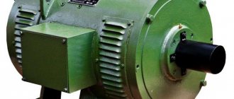
An electrical machine has two main parts—a rotating part, called the rotor, and a stationary part, called the stator (Figure 1-1).
Rice. 1-1. The usual design diagram of an electrical machine, 1
— stator;
2
- rotor;
3
- bearings.
Electrical machines also include a transformer. A transformer is a static electromagnetic device that is used to convert alternating current of one voltage into alternating current of another voltage, but of the same frequency. Although it is not a machine (it has no moving parts), its theory is still studied together with the theory of electrical machines, since the basic relationships between the quantities characterizing the operating process of a transformer are also applicable to electrical machines.
A distinction is made between AC and DC machines depending on how much current they generate or consume.
AC machines are divided into synchronous and asynchronous. In both machines, a rotating magnetic field arises during their operation. The rotor of a synchronous machine rotates at a speed equal to the rotation speed of the magnetic field. The rotation speed of the rotor of an asynchronous machine differs from the rotation speed of the field.
AC machines are single-phase and multi-phase (most often three-phase); the former generate or consume single-phase current, the latter - multiphase current.
DC machines, as a rule, are equipped with a commutator, which here serves to obtain e.g. on the brushes of the machine. d.s., constantly acting in one direction. At the same time, the collector serves to switch currents in parts of the rotor winding (armature) in such a way that the resulting electromagnetic forces resulting from the interaction of the magnetic field of the stator electromagnets and the currents in the rotor winding act on the rotor all the time in one direction.
Asynchronous commutator AC machines are also used. Their rotor is made in the same way as the rotor of a DC machine. Unlike brushless asynchronous machines, they allow you to smoothly and economically regulate their rotation speed. However, their scope of application is very limited due to their high cost, difficulty in maintaining them and relatively low operational reliability.
The practical classification of electrical machines briefly presented here does not exhaust their diversity. In the future, when considering AC and DC machines, we will refer to their various types, differing both in purpose and in implementation.
1-2. Operating principle of an electrical machine and transformer
The operating principle of an electric machine is based on the physical laws of electromagnetic induction and electromagnetic forces. According to these laws, as well as the laws of Ohm, Joule-Lenz and the magnetic circuit, it is possible to obtain the basic relationships between the quantities characterizing the working process of the machine. For this let us turn to Fig. 1-2. Shown here are the two poles of an electromagnet creating a magnetic field. A conductor is placed in a magnetic field between the poles, the cross section of which is shown in a circle. If this conductor is moved, for example, from left to right, then, according to the law of electromagnetic induction, an emf will arise in it.
, (1-1)
where in
- induction in the place where the conductor is located;
l
is the active length of the conductor, i.e. that part of it that is in the magnetic field;
v
is the speed of movement of the conductor relative to the field (if the induction
B
is expressed in V s/cm2,
l
is in centimeters,
v
is in cm/s, then we obtain the emf e
in
volts; if
B
is expressed in gauss, then to get
e
in volts, the right side (1-1) must be multiplied by 10-8).
Rice. 1-2. To an explanation of the principle of operation of electric machines.
Direction of induced e. d.s. is determined by the right-hand rule, and it should be borne in mind that this rule is given to determine the direction of e. d.s. in a conductor moving relative to a magnetic field (Fig. 1-3).
Rice. 1-3. Right hand rule.
If the ends of the conductor are closed to an external resistance, then a current will flow through it, having the same direction as the emf. This direction (from us) is indicated by a cross in Fig. 1-2.
As a result of the interaction of current i
an electromagnetic force will arise in the conductor and field
, (1-2)
the direction of which is determined by the left-hand rule (Fig. 1-4) (if B
expressed in V s/cm2,
i
- in amperes,
l
- in centimeters, then we get the force
F
EM, in W s / cm or in J / cm;
to obtain F
EM in kilograms, the right side (1-2) must be multiplied by 10.2 and with
B
in gauss - by another 10-8).
Rice. 1-4. Left hand rule.
F must be applied to it from the outside
, equal to
F
EM, i.e.
F
=
F
EM. (1-3)
If we multiply both sides of the equality of forces by the speed v
, then we obtain equality of powers
Fv
=
F
EM
v
. (1-4)
Substituting F
EM from (1-2) and
v
from (1-1), we obtain:
Fv
=
ei
. (1-5)
From this we see that the mechanical power Fv
in our elementary generator it is converted into electrical power
ei
. The power supplied to the external circuit by such a generator can be found from the voltage equation
u
=
e
–
ir
, (1-6)
where u
— voltage at the external resistance terminals;
ir
is the voltage drop in a conductor having resistance
r
.
Multiplying this equation by i
, we get:
ui
=
ei
–
i
2
r
, (1-7)
where ui
- electrical power given by the conductor to the external circuit (it is part of the total electrical power
ei
obtained as a result of the conversion of mechanical power);
i
2
r
- electrical losses in the conductor.
The same elementary machine can operate as an engine, that is, convert electrical energy into mechanical energy. Let us apply voltage u
so that the current
i
in the conductor has the value indicated in Fig.
1-2 direction. This will generate an electromagnetic force, which, according to the left-hand rule, will force the conductor to move to the left. E will appear in Explorer. d.s. e
, directed against the current
i
and against the voltage
u
, which can be verified using the right-hand rule.
Therefore, the voltage u
must balance the emf.
e
and the voltage drop in the conductor
ir
, i.e.
u
=
e
+
ir
. (1-8)
From the stress equation (1-8), multiplying it by i
, let's move on to the power equation
ui
=
ei
+
i
2
r
. (1-9)
In this equation i
2
r
- electrical losses in the conductor,
ei
- that part of the supplied electrical power
ui
, which is converted into mechanical power
F
EM
v
, since, taking into account (1-1) and (1-2), we can write:
ei
=
Blvi
=
F
EM
v
. (1-10)
The above ratios show that the electric machine is reversible, that is, it can operate as both a generator and a motor.
The principle of reversibility of electric machines was established by the Russian academician E. X. Lenz in 1833. It is applicable to any electric machine.
Thus, we see that the presence of a magnetic field and conductors through which current passes is a necessary condition for the operation of any electrical machine. To enhance the magnetic field, ferromagnetic materials in the form of steels are used.
When an electric machine operates, there is a relative movement of conductors and a magnetic field. This movement in conventional machines is carried out by rotational motion (Fig. 1-1).
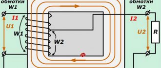
The operation of a transformer is based on the phenomenon of mutual induction. A transformer usually consists of two windings with different numbers of turns. There is a magnetic connection between the windings; to strengthen it, the windings are placed on a closed steel magnetic circuit, called the transformer core. Energy from one winding to another is transferred through a magnetic field. Due to the difference in the number of turns of the windings, a current of one voltage is transformed into a current of another voltage, increased or decreased compared to the first.
1-3. Materials used for transformers and electrical machines
The following materials are used for the manufacture of transformers and electrical machines: structural, “active” and insulating.
Structural materials are used for the manufacture of those parts and components of machines and transformers that serve mainly to transmit and perceive mechanical influences. Electrical machines mainly use the same structural materials as in general mechanical engineering: cast iron (simple, malleable), steel (cast, forged), non-ferrous metals and their alloys, plastics.
Active materials serve as magnetic and conductive (current-carrying) materials to create the necessary conditions in transformers or machines in which electromagnetic processes occur.
Some parts of electrical machines operate in difficult physical conditions, therefore, requirements are imposed on a number of materials that relate simultaneously to both their mechanical, magnetic and electrical properties.
Insulating materials are intended to electrically isolate the conductive parts of transformers and machines from their other parts and from each other.
a) Magnetic materials
. For transformer cores, special electrical steel sheets with a relatively high silicon content (up to 4-5%) are used, usually 0.5 or 0.35 mm thick at an alternating current frequency of 50 Hz. At higher current frequencies, for example at 300-400 Hz and above, the steel thickness is chosen to be 0.20 and 0.10 mm. In this case, losses from eddy currents induced by the alternating magnetic field occurring in the transformer core are significantly reduced.
For the manufacture of individual parts of the magnetic system of electric machines, various ferromagnetic materials are used: sheet electrical steel of various grades, cast iron, cast steel, sheet (structural) steel, forged steel.
Those parts of the machine where an alternating magnetic field occurs are assembled from sheets of electrical steel isolated from one another with a silicon content of up to 2-3%, usually 0.5 mm thick.
Power losses in sheet steel from hysteresis and eddy currents are characterized by specific losses, i.e. losses per 1 kg of steel at a frequency of 50 Hz and a sinusoidal change in induction at an amplitude of 10,000 Gas. They are for sheet steel used for normal machines, with a thickness of 0.5 mm - about 3 W/kg; for sheet steel with a silicon content of up to 4-5%, used for transformers, with a thickness of 0.5 mm - about 1.4-1.5 W/kg, with a thickness of 0.35 mm - about 1.3-1.2 W/kg. The specified sheet steel is called hot-rolled (according to the manufacturing method). In recent years, in a number of cases it has been replaced by cold-rolled sheet steel, which has higher electromagnetic properties (higher magnetic permeability and lower specific losses). Cold rolled steel is now widely used for transformers and large electrical machines. Cast iron is used extremely rarely for parts of the magnetic system due to its poor magnetic properties.
Cast and forged steel, as well as structural sheet steel, are used for those parts of the magnetic system of machines in which a constant magnetic field occurs.
b) Conductor materials
. These include, first of all, copper - a relatively inexpensive material with low resistivity.
Along with copper, aluminum and sometimes some alloys (brass, phosphor bronze) are also used for conductors. Copper and aluminum wires for windings of transformers and electrical machines are manufactured in round and rectangular sections with various types of insulation. Cotton yarn, telephone paper, asbestos, glass yarn, plastics, synthetic films, and special enamel varnishes are used for insulation.
Cotton insulated wires are widely used for normal transformers and electrical machines.
For machines of small and medium power (up to approximately 300 kW) for voltages up to 700 V, wires with enamel insulation are often selected. The heat-resistant enamel varnishes used in this case make it possible to obtain a thin and at the same time quite reliable insulating coating of wires.
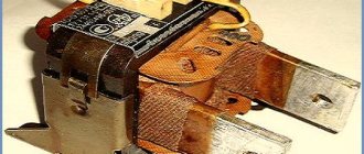
Brushes are important for the operation of electrical machines. They are placed on rotating rings or a commutator connected to a winding placed on the rotor. Thus, a sliding contact is made, through which the winding is connected to the external circuit.
c) Insulating material
s. Insulation should be considered one of the main elements of a transformer and an electrical machine. It largely determines their operational reliability.
The heat resistance of the insulating materials used to insulate the windings determines the permissible temperatures of the windings, and therefore the load of the active materials (current density for conductors, induction for steel). The thermal conductivity of the insulation, as well as its moisture resistance and chemical resistance are of great importance.
It is also required that the insulation have sufficient mechanical strength, since during the process of insulating windings, laying them on transformer cores or in machines, as well as under operating conditions, the insulation is subjected to significant mechanical forces.
Mica insulation should come first. It best satisfies the above requirements. The starting material here is mica. Mica, mica, and micafolia are made from mica, plucked into small plates. Mikanites are sheets consisting of small mica plates glued together using special varnishes. Micalenta. consists of one layer of thin plucked mica, covered with paper on both sides. Micafolia consists of one to three layers of plucked mica glued to paper; manufactured in the form of sheets. Fiberglass is also used instead of paper. Micalente and micafolium are relatively expensive insulating materials and are used mainly for high voltage machines (from 3,000 V and above).
Most often, fibrous materials are used for insulation: papers, cardboards, tapes, fabrics, etc. Their main advantages are high mechanical strength and flexibility and relatively low cost. However, unimpregnated fibrous materials are hygroscopic, have poor thermal conductivity, and have low electrical strength. Therefore, they are used for insulating electrical machines only in impregnated form, which significantly improves their properties.
Organosilicon insulating materials for covering conductors, proposed and developed in the USSR, have gained great practical importance.
To improve the insulation properties of electrical machines, it is necessary to use impregnating and coating varnishes, as well as compounds - special masses made from bitumen, drying oils and rosin.
Modern transformers, as a rule, are made of oil. Their core with windings is placed in a tank filled with special transformer oil. The starting products for its production are oil distillates.
Insulating materials used in electrical machines are divided into several classes based on heat resistance. Of these, materials of classes A and B are most often used.
Insulation Class A: Cotton, silk, paper and other similar organic materials, impregnated or immersed in oil, and a compound called enamel and used in the manufacture of enameled wire.
Insulation class B: products made of mica, asbestos, glass fiber containing binders.
In addition to insulation classes A and B, in recent years, insulation classes E, F and H have been used for electrical machines. Of these, class E occupies an intermediate position between classes A and B. Insulation classes F and H include the most heat-resistant insulating materials.
1-4. Operating modes and nominal values
The operating mode of an electrical machine or transformer under the conditions for which the machine or transformer is intended by the manufacturer is called the nominal operating mode. It is characterized by the values indicated on the nameplate of the machine or transformer and called nominal.
Typically, electrical machines and transformers are intended for a nominal continuous operating mode, in which they can operate with established temperature rises of their individual parts above the air temperature, not exceeding those allowed by all-Union standards.
Other nominal operating modes - short-term and intermittent - are characteristic mainly of electrical machines operating under electric traction or servicing cranes, elevators, presses, etc.
1-5. Heating and cooling
Any energy transformation is accompanied by losses. In electrical machines and especially in transformers, losses are relatively small, but the size of machines and transformers depends on them, and not just their efficiency. These dimensions are calculated in such a way that the heat generated due to losses in steel, windings and friction can be released to the environment when the temperature of the heated parts slightly exceeds the ambient temperature. The temperature rise should not exceed certain values, depending on the heat resistance of the insulating materials used.
The ambient (air) temperature is conventionally taken to be 35° C. The permissible temperature rise above this temperature for class A insulation is taken to be 55-70° C; with class B insulation - 70-95° C; for insulation classes E, F and H, the approximate permissible values of temperature rise are respectively: 70-75, 90-105 and 115-130 ° C (the specified limits of permissible temperature rise values depend on the design of the windings and on the method of temperature measurement).
Permissible temperature values, determined on the basis of long-term operating experience of electrical machines and transformers, correspond to a service life of insulating materials of approximately 20–25 years. It decreases noticeably as the temperature increases above the permissible temperature. At the same time, faster “aging” of the insulation is observed, which manifests itself primarily in the deterioration of its mechanical properties (the insulation becomes brittle and mechanically weak).
Heat transfer depends not only on the size of the cooled surfaces, but also on the intensity of movement of the air washing them (or other cooling medium). The use of a properly selected cooling system (ventilation system) contributed to the progress of electrical machine and transformer manufacturing and made it possible to build machines and transformers with enormous power (500,000 kW and above in one unit).
1-6. Brief historical information
One of the most important physical laws that determine the principle of operation of electrical machines and transformers, the law of electromagnetic induction, was established by M. Faraday in 1831.
In 1833, member of the St. Petersburg Academy of Sciences and professor of St. Petersburg University E. H. Lenz presented a work in which he deeply generalized the law of electromagnetic induction, formulated the principle of reversibility and showed that both phenomena - rotation under the influence of electromagnetic forces and electromagnetic induction - are closely related to connected to each other.
Subsequently, many of the works of E. X. Lenz were associated with the works of the Russian academician B. S. Jacobi, the inventor of the first electric motor with rotational motion. Jacobi also pioneered the use of a commutator, which is a necessary part of a commutator machine.
The electric motor he built was the world's first electric motor used for practical use. The engine was used to propel a boat on the Neva (1837). At the same time as he was working on improving his engine, Jacobi was engaged in many other issues of electrical engineering. His work on mines was of great importance. Jacobi used induction coils to transmit electrical impulses to mine fuses over a distance of about 9 km. Thus, the transmission of electricity was carried out for the first time during its transformation using induction coils.
However, P.N. should be considered the inventor of the transformer. Yablochkov, who first used it to convert alternating current in industrial installations in the 70s of the last century.
From the advent of the Jacobi engine until the 80s of the last century, the development of practical electrical engineering went mainly in the direction of improving the direct current machine. In many cases it has replaced expensive and ineffective galvanic cells.
The first practical installation of alternating current was carried out by P.N. Yablochkov in 1878 to power the “Yablochkov candles” he invented. At the same time, he created an alternating current generator with a winding on the stator, in which alternating current was induced by the magnetic field of rotating electromagnets. Current was supplied to the windings of the latter using slip rings and brushes placed on them from a special direct current generator. Such an alternating current generator was the prototype of modern synchronous machines.
Induction coils, as they were called at that time, used by Yablochkov in his “candle” installations, had two magnetically coupled windings placed on an open core. Such induction coils served to convert alternating current and were essentially transformers.
Despite the fact that by the mid-80s of the last century the advantages of alternating current for the transmission of electrical energy were identified, which was greatly facilitated by the work of our compatriots F.A. Pirotsky, D.A. Lachinov and others, still in most cases When choosing a power system, they settled on direct current, since a sufficiently advanced alternating current motor did not yet exist. Such an engine was created in the late 80s by our compatriot M. O. Dolivo-Dobrovolsky. It was a three-phase asynchronous motor, which is currently the most common electrical machine.
1-7. Transformer manufacturing and electrical engineering in the USSR
Tsarist Russia had almost no electrical machine-building industry of its own. Those small factories that existed in St. Petersburg, Moscow, Riga, and Revel were not independent. They belonged to foreign companies, which found it unprofitable to develop electrical engineering in Russia. The factories that existed were in reality more like assembly shops, where cars were usually assembled from parts imported from abroad.
The leading employees at the factories were foreign engineers and technicians.
Despite such conditions, Russia had its own talented engineers and scientists. They were able to fully apply their knowledge and abilities only after the Great October Socialist Revolution. They played a significant role in the development of electrification of the USSR.
With their participation, Lenin's GOELRO plan was developed, power stations and electrical industry plants were expanded and built.
Electrical engineering and its most important field—electrical mechanical engineering—reached its true flourishing in Soviet times. Large factories and power plants quickly sprang up. Soviet technical educational institutions and factories produced new cadres of qualified specialists who were able to solve complex technical problems.
During the years of Soviet power, mainly during the first two five-year plans, our electrical engineering industry had to go through the path that foreign technology had to go through for almost half a century.
Quickly mastering new types of machines, widely introducing socialist forms of labor into production, on the basis of broad planning, the electrical machine-building industry of the USSR had qualitatively and quantitatively reached the level of foreign technology by the end of the second five-year plan.
All basic and special types of transformers and electrical machines - direct and alternating current machines, the largest generators and transformers - are currently manufactured in factories in the USSR. The successes of Soviet electrical engineering are due to the very system of our planned economy and the desire of the Soviet people to work for the general advancement of the entire national economy.
The power of our technology was especially evident during the Great Patriotic War and in the post-war years. At this time, new electrical machine-building plants were created, which supplied the industry with the necessary electrical machines and transformers.
Currently, we have electrical machine-building factories in almost all republics of the Soviet Union, which annually produce millions of electrical machines and transformers of various types with powers ranging from fractions of a watt to hundreds of thousands of kilowatts.
Soviet electrical machine builders have preserved the best traditions of their famous compatriots - V. Petrov, E. X. Lenz, B. S. Yakobi, A. G. Stoletov, P. N. Yablochkov, D. I. Lachinov, M. O. Dolivo-Dobrovolsky and other outstanding scientists and engineers who worked in the last century, from the very beginning of the development of electrical engineering, and who made a lot in this area with their scientific discoveries and inventions.
Soviet scientists and engineers have made great strides forward in recent years.
The Soviet Union created such machines as turbogenerators with a capacity of 320,000 kW and 3000 rpm, the largest hydroelectric generators in the world, powerful transformers with a capacity of 500 kV, and many types of normal and special electrical machines and transformers. We now have many highly qualified specialists, the number of which is constantly growing.
It is necessary to mention the teams named after S. M. Kirov in Leningrad, Dynamo named after S. M. Kirov in Moscow, KhEMZ and the heavy electrical engineering plant in Kharkov, YaEMZ in Yaroslavl, Uralelectroapparat in Sverdlovsk, MTZ (Moscow Transformer Plant) named after V V. Kuibyshev in Moscow, having great achievements.
Types of rotating electrical machines
By the nature of the magnetic field in the main air gap
Single pole machine
- a rotating electric machine in which the normal component of magnetic induction at all points of the main air gap has the same sign.
Opposite pole machine
- a rotating electric machine in which the normal component of magnetic induction in different parts of the main air gap has different signs.
salient pole machine
- an opposite-pole machine in which the poles protrude towards the main air gap.
Non-salient pole machine
- opposite-pole machine with a uniform main air gap.
AC machine windings
Previous | Contents | Next >>§ 90. WINDINGS OF AC MACHINES
The winding of the machine is a very essential part, since it creates e.g. d.s. and the process of energy conversion occurs.
Depending on the purpose of the power and the operating conditions of the machine, the windings have a different design. The following main types of windings are used in AC machines: 1) coil, 2) rod, 3) special.
Coil windings are made from insulated copper or aluminum wire with a round cross-section, rod and special windings are made from bars with a rectangular cross-section. Special windings are used for short-circuited windings of rotors of asynchronous motors, for starting and settling windings of synchronous machines, for single-armature converters, etc.
Structurally, the windings can be made, depending on their location in the slots, single-layer or double-layer, depending on their manufacture - manual and template, depending on the number of slots per pole and phase q - with an integer and a fractional number.
In AC machines, two-layer windings are mainly used. In low-power machines, a single-layer winding is used, the manufacture of which is difficult. With a single-layer arrangement of active conductors in the grooves, the frontal connections located on the end sides of the stator or rotor will lie in the same plane, which makes it impossible to make a template winding. In Fig. 109, a
two coils of the same phase of a single-layer winding are shown. The coils consist of active conductors spaced from one another at a winding pitch distance y, approximately equal to the pole division, i.e., the distance between the centers of opposite poles. The end-to-end connections between wires 1 and 1+y, 2 and 2+y, etc. are in the same plane, and therefore, when winding, these end-to-end connections must be bent in different directions.
In a single-layer winding, the end connections can be in different planes if the order of connecting the active conductors is changed, as shown in Fig. 109, b. However, with such a winding, the coils have different sizes, and, therefore, several templates are required to make such a winding.
In two-layer windings (Fig. 109, c), the active conductor located in the upper layer of the groove is connected to the conductor located in the lower layer of the groove, which is located at a distance y from the initial one. With such a winding, the frontal connections do not intersect and are located in different planes, which makes it possible to perform a template winding with the same size and shape of the coils.
Windings can be single-phase or multi-phase. Three-phase windings are most widely used. The power of a three-phase machine is 1.5 times greater than the power of a single-phase machine with the same dimensions and energy loss. In Fig. 110 shows the simplest three-phase winding and its expanded diagram. This winding consists of three identical coils, the axes of which are shifted in space by 120°. When a magnet with poles N and S rotates, e will be induced in these coils. d.s, equal in magnitude and shifted in phase by .1/3 of the period.
Windings in which the phase consists of one coil are not used. In practice, distributed windings have become widespread, in which the turns belonging to one phase are evenly distributed between several pairs of slots. With such a winding, the shape of the magnetic induction curve in space is closer to a sinusoid.
However, in distributed windings there is a slight decrease in e. d.s. This is explained by the fact that the axes of the coils connected in series to one phase do not coincide, and therefore do not coincide in phase e. d.s induced in these coils. E.m.f. phase is equal to the geometric sum e. d.s. components, this phase of the coils, which will be less than the arithmetic sum of these e. d.s.
To improve the shape of the e.m.f. curve. The windings of alternating current machines are made with a pitch smaller than the pole division (with a shortened pitch). However, shortening the winding pitch also leads to a slight decrease in e. d. s, since in that case the winding coils are not penetrated by the entire flux of the pole, but only by part of it.
Thus, the effective value of the emf. AC machine phases
where Ko is the winding coefficient (less than unity), taking into account the decrease in e. d.s. machine due to the distribution of the winding and shortening its pitch,
w is the number of turns of one phase of the winding, equal to the product of the number of turns of one coil by the number of series-connected coils.
Previous | Contents | Next >>