Almost all automated systems contain a device such as a limit switch, which is responsible for turning them off when the moving part reaches a certain point. In lighting control systems, limit switches are used as sensors. When programmed circumstances occur, they generate a signal.
We will tell you everything about the functional purpose and types of limit switching devices. The article we presented describes practical-tested wiring diagrams and lists connection rules. Features of marking are given and advice on selection is given.
Design and operation of the switch KV-1, KV-2
The operating principle of the KV-1 (single-position, two-channel), KV-2 (two-position, single-channel) linear movement devices - limit switches is to use a permanent magnet printed circuit board with two reed switches, they are used as the main elements that switch the electrical circuit. In addition to the board in the “limit switch” housing, the limit switch device contains a terminal block; in the main (first) housing there are two blind holes in which the rod goes; for KV-02 there are 2 rods. A permanent magnet, a magnetic circuit and a return spring are attached to the rod. The action of the rod is reciprocating, with its help the magnet moves and closes and opens the contacts.
Rice. No. 1. Photo of the limit switch KV-01, KV-02.
Rice. No. 2. Schematic electrical diagram of limit switches KV-01, KV-02.
Rice. No. 3. Drawing of the KV-1 limit switch indicating the overall and installation dimensions of the KV-01 and the location in the cable entry structure.
Switch blocks
To automate the operation of devices, switch blocks are used, which provide more precise adjustment of electric drives in automotive and household appliances.
The use of limit switch blocks allows you to achieve the following goals:
- Setting up torque and travel switches without disassembling the body of the electrical device. The remote control is used for setup.
- Activation occurs as soon as the output shaft reaches the preset position.
- When critical torque values are reached, torque switches are activated.
- If the locking elements fail, the sensors are blocked.
Optical sensors
Such contactless switches today find their wide application in many branches of human activity, where the equipment necessary for detecting objects operates. When connecting a contactless sensor, coding is used. This allows you to prevent false operation of the device due to extraneous influence of light sources. Such sensors also work at low temperatures. Under these conditions, thermal casings are put on them.
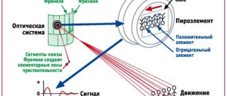
What are optical unsupervised sensors? This is an electronic circuit that responds to changes in the light flux that falls on the receiver. This principle of operation makes it possible to record the presence or absence of an object in a particular spatial area.
The design of optical contactless sensors has two main blocks. One of them is the radiation source, and the second is the receiver. They can be located in the same or in different buildings.
When considering the principle of operation of a contactless sensor, three types of optical devices can be distinguished:
- Barrier. Optical switches of this type (T) operate on a direct beam. In this case, the devices consist of two separate parts - a transmitter and a receiver, located coaxially relative to each other. The radiation flux emitted by the emitter must be directed exactly to the receiver. When the beam is interrupted by an object, the switch is activated. Such sensors have good noise immunity. In addition, they are not afraid of raindrops, dust, etc.
- Diffuse. The operation of type D optical switches is based on the use of a beam reflected from an object. The receiver and transmitter of such a device are located in one housing. The emitter directs the flow to the object. The beam, reflected from its surface, is distributed in different directions. In this case, part of the flow returns back, where it is captured by the receiver. As a result, the switch trips.
- Reflex. Such optical proximity sensors are type R. They use a beam reflected from a reflector. The receiver and emitter of such a device are also located in the same housing. When the beam hits the reflector, it is reflected and ends up in the receiver area, as a result of which the device is triggered. Such devices operate at a distance to the object of no more than 10 meters. Perhaps they can be used for fixing translucent objects.
Starline alarm shows open hood
How to install starline a91 dialog
StarLine A91 Dialog is a modern car security system with a radio control dialogue code “Quick Dialog” and an engine auto-start function. Thus, “Quick Dialogue” is considered a control code with individual encryption keys, which excludes intelligent electronic hacking. Resistant to all code grabbers. In order to protect the code, we apply the dialog code algorithm perfected at this stage. Complemented by the innovative frequency hopping method. In this method, when transmitting commands, the patented OEM transceiver changes frequencies many times according to a special program during the period of each transmission. A solution of this level, which is a method of spreading the spectrum with frequency hopping, is being used for the first time in an alarm control system and is a significant complication of all kinds of attempts to crack the code.
Functional features of StarLine S96 v2 BT GSM GPS
- Smart authorization via bluetooth smart
- Record energy efficiency (guarantee of sufficient battery charge for up to 60 days in security mode)
- Super slave
- Protection against key theft (additional authorization with a pin code using standard car buttons)
- Invisible blocking (thanks to the unique patented technology of hidden engine blocking using the car’s standard digital tires)
- Remote autostart
- Smart auto diagnostics
- 2can+4lin - module
- Smart Keyless Bypass
- Phone control
- Navigation module with GLONASS+GPS antenna
- Free monitoring
What is a car alarm
The possibility of increased control and warning range, as well as reliable operation in extreme urban radio interference, is ensured by the use of a 128-channel patented transceiver with FM modulation and a narrow bandwidth.
Thanks to a specialized signal processing program, narrow-band filters, as well as reception and transmission channels optimally distributed along the edges of the 433.92 MHz frequency range, it became possible to improve the signal-to-noise ratio by 8-10 dB and double the range and noise immunity.
Remote starting and control of the operation of various types of engines is provided by a specialized processor. The existing key fobs implement an intuitive control principle. The pictograms on the keychain are presented in Russian.
The StarLine A91 Dialog car alarm can be installed on various cars with gasoline, diesel or turbocharged engines, with an automatic or manual transmission.
Thanks to more than 60 standard, programmable functions, not only reliable protection is provided, but also comfort when using a car alarm such as StarLine A91 Dialog.
Installation process
First of all, let's consider what you will need when installing a car alarm:
- signaling;
- driver's door activator;
- screwdriver;
- soldering iron, solder, rosin;
- insulating tape;
- additional protective diode.
The first step is to remove the steering shaft trim, then unscrew the 2 self-tapping screws securing the instrument panel trim, and just below that there is another self-tapping screw and a nut. Next, you need to install an LED in the left windshield pillar, a shock sensor on the cross beam, and install a service button in any convenient place. The antenna is mounted on the windshield.
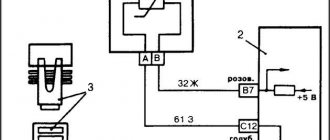
The process of connecting the 18-pin connector of the alarm unit (required wires for connection):
- black wire - ground;
- a short loop of black wire - if the automatic transmission is left in a loop, if it is a manual transmission, it is cut;
- green-black and green-yellow wires are connected to the turn signal lamps;
- gray wire - siren control output;
- blue-black wire - door limit switches;
- the orange-gray wire is connected to the hood end switch, it also needs to be connected to the engine temperature sensor;
- the orange-white wire must be connected to the trunk end;
- The pink wire is connected to the minus of the “immobilizer bypass”;
- gray-black wire - control by generator signal during automatic start;
- orange-violet wire - connects to the handbrake.
How to connect the 6-pin autostart connector:
- The red wire is plus “+12V” (the pink wire for the central lock).
- The yellow wire is the IGN1 output for maintaining the ignition.
- The blue wire doesn't connect anywhere.
- The black-yellow thick and black-yellow thin wires are connected as follows: cut the red wire of the ignition switch, then the thick wire to the starter, and the thin wire to the ignition switch.
- The green wire does not connect anywhere.
Who makes limit switches
Many companies produce such sensors. Among them there are recognized leaders. Among them is the German company Sick, as the main manufacturer of such high quality products. Autonics supplies the market with contactless limit switches of inductive and capacitive types.
High quality contactless sensors are produced by the Russian company. They are characterized by ultra-high tightness (IP 68). These limit switches operate in the most hazardous environments, including explosive ones, and various installation methods are available.
Ukrainian limit switches are popular. Switches and limit switches VP, PP, VU are produced here. The warranty, subject to compliance with all operating rules, is 3 years.
Installation and connection - step-by-step instructions
Connecting mechanical type limit switches is not difficult and is no different from the installation method of a standard device. A phase break connection is made to contacts of the required type (normally closed or open). The difficulty lies in the installation and adjustment of the HF, which requires correct location on the supporting structure.
It is necessary to install the device body so that the roller is in contact with a given element of the moving part, but does not protrude too far forward, risking breaking. If the moving structure is large in size and weight, it can vibrate during movement, which must be taken into account when adjusting the position of the roller.
For such structures, it is more correct to use switch models with an adjustable lever to adjust the position of the roller in place. Let's consider the procedure for installing HF on sliding gates. To work you will need:
- Welding machine.
- Screwdriver, set of wrenches.
- Pliers.
- Bulgarian.
- Roulette, ruler.
- Point probe for identifying phase wires.
Step-by-step instruction:
Step 1. Mark the extreme positions of the leaf when the gate is closed and open. Weld metal platforms on the supports (guides) for installing the HF. At the same time, it is recommended to secure the metal pipe into which the wire will be placed.
We install a place for limit switches
Step 2. Place the sash in its extreme position and mark the centers of the holes for the bolts on the support platform. Perform the same steps on the second site. Drill holes and secure switches.
We fasten the mechanism itselfStep 3. Unscrew the caps and connect the wires, previously tightened into the pipe with wire. Connect the wires to the control panel and check operation. Adjust the position of the switches and, if necessary, install additional stops to ensure reliable interaction of the rollers with the moving sashes.
Connect and check functionality
LOVATO company
There are many companies that manufacture and assemble such devices. LOVATO ELECTRIC has become quite popular and famous among them.
The LOVATO roller limit switch differs from the rest in that, like other models from this company, it has a fairly simple and understandable design. This allows you to mount and install the device quite simply and quickly. The simple design also allows for quick and hassle-free parameter settings. The reliability of the operation of such devices is guaranteed by the manufacturer itself. The casings of these devices are completely removable, and a threaded screw is used to fasten them. The models were also equipped with new bayonet heads, which allows you to easily remove and replace the working heads without the use of additional tools or accessories. The heads of these devices rotate in the axial plane at an angle of 45°. There are also additional blocks that are removable.
Connection procedure and specifics
Connection diagram
Although the limit microswitch itself is designed quite simply, it can be used in technological equipment rich in electronics. It follows from this that it should be connected by an experienced specialist who is well versed in switching circuits of electronic components.
A typical example of such a connection is the installation of a mechanical switch in a typical 3D printer, during the operation of which it is necessary to fix the extreme position of the carriage. The mounted switch has 3 contacts with the following designations: COM, NO, NC. In the open state, the first and third terminals have a voltage of +5 Volts (while the second contact is reliably grounded). When the movable carriage reaches its extreme position, a connection appears between COM and NC, after which it locks and rebounds by approximately 2 mm.
Such a sensor is connected via two conductors in red and black insulation. When installing another type of switch (with an indicator), a more complex circuit is used, in which another conductor is provided - in green insulation. When the push-type microswitches in the printers are triggered, the LED lights up and a characteristic click is heard. Its connector, located on the switching board, has special designations:
- the red wire is marked as V (+5 Volts) and is used to connect the corresponding voltage;
- the black conductor is connected to point G (or ground);
- The green bus is set to S (signal).
The same signs are also present on the optical limit switch connector, which more accurately fixes the position of the carriage.
It works completely silently, reaching the extreme position is accompanied by LED indication. Its disadvantages include the possibility of failures due to heavy dust or exposure to direct sunlight.
Connecting limit switches to a CNC machine on grbl
Buy a limit switch: https://ali.pub/2j4i1d
So first, let's discuss why limit switches are needed. As the name of this tool implies, it serves to mark the ends of something, for example, in CNC (CNC) machines it serves to mark the end of the X, Y or Z axis.
What is it for? Well, if our CNC (CNC) does not know where its dimensions end, it will move, rest against its end of the axis and will hammer there until either the engine burns out, or something else breaks, or the drawing is screwed up.
Therefore, to avoid a disaster, we will connect the end caps to our machine.
For a burner, only 4 limit switches are enough. Two for each Axis.\
Limit switches are also used in 3d printers to calibrate the 3d printer itself, but as far as I understand, grbl does not have a calibration function. In grbl, limit switches are for safety only.
There are several options for connecting limit switches to Arduino. But since I used only one option, I’m describing it to you. Here is the connection diagram:
This diagram shows 6 limit switches connected, two for each axis. But since in my case the laser burner has two axes, I omit the Z axis. But if you have any kind of engraver, then this will be useful for the Z axis.
If you use CNC Shield like me, you will need to connect them according to this scheme:
Where pins Y+ and X+ correspond to pins 9 and 10 of the Arduino.
Important!: There is a small typo in the diagram, the Y axis is connected not to Y-, but to Y+. There is also this way of connecting limit switches, which I have not used:
There is also this way of connecting limit switches, which I have not used:
And so now let's move on to the grbl firmware. Namely, let's see what values need to be changed to turn on the limit switches.
We need to change parameter $21 from 0 to 1. This way we will turn on the limit switches and everything will work for us. But if you connected the limit switches using the second method (according to the second connection diagram), then you will also need to change parameter $5 to 1.
There are several more parameters that are used to work with limit switches in the grbl firmware, but I did not use them, I just came across them on the Internet, but you can always read about them in the description of all the values in the grbl firmware.
For those who use a CNC machine based on V-slot profiles, I will show you what fasteners I used for the limit switches.
This mount is suitable for limit switches, which are linked at the beginning of the article.
In principle, I told you everything I wanted to tell you. You can see everything more clearly in the video:
Principle of operation
A limit switch or limit switch is a device that issues a command or personally opens/closes the electrical circuit of an actuator. The command signal is the appearance of the impact of the moving part on the switch. It is designed to automate management and free people from performing repetitive and primitive actions. This is the purpose of his work.
Limit switch as the most common equipment
Externally, it is an independent compact device installed in a controlled mechanism. This is not considered the starting or ending point of the journey. In order to influence the limit switch, parts can be used that are located anywhere in the cabinet. Often, movement is ensured by the same switch, which is in contact with the moving unit.
Note! The limit switch supplies or switches off voltage according to position. It can have either a direct mechanical effect or an indirect effect. So, it can create a push with touching or pressing, or ultrasound with infrared radiation
So, it can create a push with touching or pressing, or ultrasound with infrared radiation.
Design
Looking at the photo of the limit switch, you can see that it consists of 2 or 3 main parts:
- Dielectric or current-conducting housing (depending on purpose and design).
- A moving mechanical part that responds to pressure. Contactless and electromagnetic ones do not have it. This part is missing from their design.
- A group of normally open/closed contacts that control movement or provide a signal.
It resembles a box of small or even miniature sizes with a moving part in the form of a button, wheel or lever.
Advantages of contactless models
The main advantage of contactless switches is energy savings. Electricity is not wasted when there are no people in the room. The person does not need to be involved to turn the light on or off. Therefore, the use of such models is considered comfortable.
Technical simplicity is an advantage of standard contact switches, but there are some disadvantages:
- Small resource when applying maximum load. If the contacts open, a spark occurs, causing the switch to break. In the presence of direct current, a capacitor connected in parallel to the contacts will help eliminate the accident. If AC networks are present, you will need a refractory tungsten solder.
- The downside of the contact device is considered to be strong sensitivity to dust and dirt. This causes a disruption in the electrical circuit. Next, there is a decrease in the interaction of contacts, and as a result, overheating and breakdown.
A huge selection makes it possible to find an element to use in a particular case. If you need to implement touch control, a capacitive switch is suitable, but for use in dirty conditions it is better to choose an inductive option.
Problems and solutions
The design of a mechanical type HF is not difficult, however, malfunctions sometimes occur during operation. They are usually associated with burnt contacts or installation errors:
Table 2. Common problems with mechanical limit switches.
| Malfunction | Probable Cause | Elimination method |
| Breakdown of the switch to ground or unacceptable decrease in insulation resistance | The wire touches the housing, water enters the housing | Tighten the screws of the contact outputs. dry the switch |
| No contact | Burnt or burnt contacts | Clean contacts, reconnect burnt contacts |
| Trigger point spread | Play in the fastening of the switch or the entire device | Tighten the screws securing the switch or the entire device |
Video - Repair of limit switches on automatic gates
Mechanical limit switches perform simple but important tasks. Failure to operate the device can lead to accidents, destruction of equipment and injury to people, so the requirements for the reliability of the design are strict. Existing types of HF demonstrate reliable and trouble-free operation, ensuring the stable flow of technological processes or the safe operation of general-purpose equipment.
What does the marking say?
Contactless switches are supplied to the market by various manufacturers. Among them are Western, domestic and Chinese companies
When purchasing, it is important to pay special attention to the quality of the units and the reputation of the manufacturer.
Due to the seriousness of the regulated processes, which are controlled by various modifications of sensors, you should only choose products that have accompanying documentation - instructions with installation diagrams, operating conditions and a list of technical parameters.
On the body of the device itself, manufacturers indicate its characteristics in the form of a set of letters and numbers - mark
Among these designations, some important information is encrypted, which is used when choosing the right model. Not all indicators can fit on a small area of the switch. The rest that are important to the consumer are contained in the user manual
The rest that are important to the consumer are contained in the user manual
Not all indicators can fit on a small area of the switch. The rest that are important to the consumer are contained in the user manual.
If the model you like does not come with instructions, then you should not buy it - it may be a fake. Moreover, some of the necessary parameters will remain unknown, and you cannot take the seller’s word for it.
Each company that produces switching devices for electrical circuit control has developed its own designation system. Its decoding is given in the catalog, which also contains the range of products offered.
The need for marking did not arise by chance - there is a wide variety of switches. In addition, they can be classified according to various principles.
For example, depending on the function performed during switching, devices are divided into the following categories:
- switching on (NO) – A;
- shutdown (NF) – B;
- switching – C;
- programmable option – P;
- other – S.
Depending on the installation method, sensors can be recessed, non-recessed, and others.
If the company uses the marking principle recommended by GOST, then the inscription on the switch will, for example, look like this:
U3 A30 A D2
Where:
- U – ultrasonic method of detecting an irritant. The rest correspond to other Latin letters: I – inductive, C – capacitive, D, R and T – direct, reflective and barrier photoelectric, respectively;
- 3 – installation method is different;
- A30 – shape and diameter, which in this case means cylindrical with a thread with a diameter of 30 mm;
- A – element switching function, which means switching on (NO);
- D – number of wires for direct or alternating current output, which corresponds to two connectors for direct current;
- 2 – plug-in connection method.
In total, there are 4 combination options, among which one corresponds to ribbon wires, two is considered above, three corresponds to a clamp, and four corresponds to another method.
Among the conscientious manufacturers are ZAO Sensor/Sesor, the German company Fotoelektrik Pauly, NPK TEKO, PKF STRAUS, ZAO Meander, the companies OWEN and SKB IS, NPP PRISMA from Yekaterinburg and others.
Many of them offer the service of manufacturing VBs with the parameters required by the consumer - to order.
Group of contactless devices
They were developed as a counterweight to mechanical ones; they are more advanced. They operate from transistor switches, the open position of which sets a small resistance. Non-contact start-up and shutdown prevent contacts from burning when electrical circuits are broken. Contactless switches can be:
- Capacitive. Interact with the human body. When it approaches it, an electrical capacitance will appear, triggering the multivibrator circuit located in the middle. With further approach, the capacitance increases and the pulse frequency decreases. Such elements have significant sensitivity. The functionality depends on the plate attached to the capacitors.
- Inductive. Such electronic devices are recalled after movements of magnetic materials and are equipped with metal or non-magnetic cores. When the triggered object moves, electrical impulses are sent to the threshold element, and a closing/opening signal is received.
- Optical. A special subtype, such switches have an infrared LED and a transistor that can detect the incoming signal. The optics operate regardless of the level of natural light. If the LED beam is interrupted, the photocell will be closed and the execution mechanism will turn off.
- Ultrasonic. It cannot do without quartz sound emitting elements. They can also act as motion or volume sensors. When they enter their area of action, the amplitude of sound signals of a certain frequency, which is not distinguishable by the human ear, will change.
Mechanical limit switches
They have different designs depending on the application. They are usually divided into three large groups:
- push-button;
- roller;
- lever
In most cases, they are used by metallurgists, builders and specialists in the field of mechanical engineering. They are additionally equipped with rubber seals and include a group of making and breaking contacts.
Magnetic and automotive varieties
Electromagnetic limit switches (reed switches) interact with a constant magnetic field. Made up of one or more contacts with special ferromagnets. If a magnet approaches them, they close and trigger a signal to the control circuit. The main advantage of the devices is that there is no mechanical impact at all. This significantly increases service life. Magnetic switches are produced in glass or plastic cases, their sizes are very small.
Spindle and pneumatic models
Spindle devices limit the movement of mechanisms or act as limit switches in cyclic control.
The rotating mechanism switches the internal contact group. Used on winches and other shafts that rotate at low speed. Equipped with several contact groups. Pneumatic limit switches are devices that stop the flow of compressed air or other gases after pressing a button or lever. Another type is triggered when a certain pressure level is reached in the system.
Experts remind: all work on connecting and disconnecting switches must be carried out in a complete absence of voltage. The test is carried out using a voltage indicator, and metal housings are subject to mandatory grounding.
Classification by principle of action
There are three main groups of limit switches: mechanical, non-contact, magnetic. The main function of all these devices is to automatically disconnect the working mechanism the moment its moving part reaches the set position. These switches serve not only to open a circuit, but also to connect it.
The operation of the circuit in the end sensors is coordinated in two ways: by direct action on the moving contacts and by positional control of them. In the first case they are called contact, in the second - non-contact. An example of contact limit switches are sensors responsible for closing car doors.
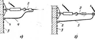
The photo shows the design of a track-type limit switch. Its main components are: cover (1), base (2), contacts (3), roller (4), lever (5), sealing strip (6), wire entry (7)
Sensors of this type can not only turn mechanisms on and off, but also establish the position of the object being monitored. These include float switches, as well as sensors that determine the fuel level. The signal for their operation is a change in resistance corresponding to a certain level of liquid.
The disadvantage of contact sensors in the presence of mechanical moving parts is a relatively short service life due to ineffective protection from moisture and dust. The advantage is simple design, installation and operation. Contactless switches are much more reliably protected from external influences. Their resource is also longer.
Mechanical type limit switches
The control of limit switches of this type can be roller or lever. They are triggered as soon as the control mechanism in the form of a wheel, button or lever experiences mechanical impact.
In this case, the position of the contacts changes - they can close or open. The process is accompanied by a signal - control or warning.
Most often, limit switches have two contacts - open and closed. There are single end devices, but they are rare. In any case, there are contacts in each case, and a working diagram with their numbers is shown on the panel.
The design of roller VCs provides for switching off by pressing the actuator on a button in the form of a small rod. Since it is connected to dynamic contacts, at the moment of contact the supply circuit opens.
The difference between lever switches is that their movable contacts are connected to a small lever by means of a rod or a rod. The action occurs when the actuator presses this lever.
The photo shows a mechanical limit microswitch KW4-3Z-3 with a pressure bar. It differs from the standard one in the stroke of the working element. It is used in CNC machines and 3D printers
In addition to standard end devices, there are microswitches. They work on the same principle, but their adjustment during installation requires greater precision due to the small stroke. To increase the working stroke, they resort to such a technique as including an intermediate element in the circuit - a lever with a roller.
This type of switches is used both in production and at home. A large number of control units are used in the elevator design.
Among them is a switch in the form of a sensor that limits the minimum and maximum height of the elevator, signals a rope break, gives a signal to open the door and performs many other actions. There are microswitches on the doors of many apartments that turn on the light in the room when it is opened.
In automobiles, such mechanical end sensors are included in alarm and lighting circuits. Their feature is the presence of one input with a positive potential connected to it. The housing is the negative terminal, pressed against a metal element on the car body that is free of paint.
This element is connected to the vehicle ground by a cable. The main condition is that the switch should not come into contact with a wet surface. Connect the end sensors when installing a car alarm using a diagram. Their outputs can be installed both on the doors and in the interior on lighting fixtures.
To turn it on when the door is opened, and turn it off when it closes, a short circuit to positive is performed. If there is illumination of the interior ceiling and doors, a block of limit switches is used, which performs various functions. As a result of the block being triggered, important sensors are blocked when attempting to open the locks.
Features of contactless limit switches
One of the varieties of limit switches is their non-contact modification (BVK). The communication of the devices is configured to trigger when a specific object enters the sensitivity zone.
These limit switches are adjusted to a specific material and a given size. As soon as an object with such parameters enters the sensitive zone, the amplitude of the generator oscillations is transformed
There are no moving parts in the device itself, and there is no mechanical contact between the object of influence and the switch element configured for it.
The BVK consists of the following parts:
- sensitive element;
- power key;
- component that analyzes the signal.
The distance at which the device begins to operate is set based on the modification of the sensor and the requirements of the process. The exclusion of both moving and rubbing elements significantly increases the reliability of these devices.
Contactless sensors, or proximity sensors as they are also called, have extensive functionality. There are two categories - switches and position sensors.
The first task of the BVK is to detect the position of an object. In addition, the sensor performs counting, positioning, separation, and sorting of objects. It can control speed, movement, calculate rotation angle, correct skew and perform many other actions.
In domestic conditions, contactless switches are still primarily used in lighting control. However, in the field of arranging Smart Home systems, it has a much larger scope of application and much more prospects.
Sensitive devices are used in industry, in the transport industry, as an element of automation, and in oil refining. Based on the principle of detecting approaching objects, BKVs are distinguished between inductive, capacitive, optical, and ultrasonic.
Inductive proximity sensors
They are tuned to materials both metallic and amorphous. Among those reacting to metal there are magnetic and ferromagnetic options. Inside the sensor there is a core - metal or magnetized.
The switch can receive power with a wide range of voltage values - from 10V at direct current, alternating - from 264 V. The output signal is created at 0.2 A in the case of direct current and 0.5 A in alternating current
If we describe the design of such a sensor in more detail, it consists of a converter that includes a copper coil located in a ferrite cup. Its functions include redirecting the vector of electromagnetic lines to the front part of the switch.
The oscillator in the circuit can be either with a fixed negative resistance or any other type. The magnetic field lines are oriented perpendicular to the direction of the current flowing through the turns of the magnetized core.
The alternating force field is caused by the alternating voltage at the core inputs. The next important component is the signal conditioner, which creates hysteresis and the range of action of the control signal. It includes a trigger controlled detector.
The diagram shows an inductive motion switch in action. Its main element is an inductor driven by a generator
The key to the operation of an inductive limit switch is the changes that occur when an object approaches or moves away. As soon as the voltage threshold exceeds the permissible value, the sensor is activated by connecting a trigger that opens the key.
Capacitive proximity limit switches
After the object appears, the vibrator circuit of the capacitive device is started, and time parameters are set. As the object approaches the sensor, the capacity of the latter increases, and the frequency generated by the multivibrator decreases.
As soon as the frequency threshold is exceeded, the device will turn off. Many models of motion sensors operate on this principle, turning off and on light bulbs when an object is detected in the sensitivity zone.
The block diagram of a capacitive sensor is similar to an inductive device: both models contain a generator and a detector.
The principle of operation of a capacitive type limit switch is based on changing the capacitance of the receiving element - the capacitor. In such sensors, the switching operation begins when dielectric and metal objects enter their field
In addition to the generator that generates the electric field, their design includes such basic parts as a demodulator. It acts as a converter of the amplitude of high-frequency oscillations with a simultaneous change in voltage. The next important component is the trigger, which is responsible for a certain signal level, switching and hysteresis dependence.
To increase the input signal to a set value, an amplifier is included in the capacitive switch circuit. The LED indicator monitors the settings and operation of the device.
An element such as a compound protects the switch from moisture and solid particles. A plastic or brass body protects everything inside it from mechanical damage. The kit also includes mounting hardware.
The switching element in this device is located on a capacitor and is a plate that interacts with a vibrator. The role of the threshold element is performed by a comparator connected to the vibrator. The latter, in turn, is connected to a frequency and voltage converter.
Capacitive limit switches react to solid materials, powdery, liquid, both electrically conductive and non-conductive
The difference between capacitive models and inductive ones is that the former react to air humidity and changes in density. The latter are insensitive to such influences.
Ultrasonic switch design
The design of ultrasonic limit switches provides for the presence of quartz sound emitters that form pulsed waves with a length of 100 - 500 kHz, and a receiver whose settings correspond to a certain frequency.
When the amplitude of sound waves changes as a result of maneuvers of a moving object, the BVK microswitch records the new values and, based on this, controls the output signals.
The operating principle of ultrasonic sensors is based on the change in time during which a sound wave travels from the sensor to the controlled object. The detection distance of such devices is quite large - up to 10 m. Their big advantage is that they can detect an object of any shape and color that reflects sound.
The operation of this ultrasonic sensor is based on a simple principle: as soon as a signal is received on one of its legs, the other receives a pulse with a length equal to the distance to the object
Such sensors are used to detect objects with a flat surface occupying a perpendicular position relative to the detection center line.
Inaccuracies in their work can cause:
- Sudden, high-power air currents that strengthen or weaken the wave.
- Sudden change in temperature. With a large amount of heat emitted by an object, the speed of the propagated waves changes.
- Deviation from the vertical of the angle between the horizontal plane of the object and the axis of the sensor. If this error exceeds 10⁰, the sensor does not operate.
- Angular outlines of the object. In this case, its identification is very difficult.
Vibrations propagate in solid, gaseous, liquid media, and the speed depends on the relevant parameters. Ultrasonic sensors have no moving parts, so there is no relationship between the number of cycles and the service life of the device. They are characterized by increased resistance to all kinds of external influences.
Optical contactless devices
BKVs of this type control objects that both block radiation and reflect it. When an object enters the space between the switch and the light source, the sensor interrupts the light output. The element responsible for this action can be a relay or semiconductor. The response radius extends up to 150 m.
This is a photo of an optical type end sensor. It determines the positions of the extreme points of movement of moving parts in 3D printers and CNC machines
Proximity sensors operate in a wide temperature range - from -60 to +150⁰С. They can withstand pressures of about 500 atm and can be used in aggressive environments and even in conditions of increased explosion hazard.
Magnetic end varieties
This type of switches, which are also called float switches or reed switches, is gradually replacing mechanical models. Their contacts change position when they are at some distance from the magnet. In this case, a signal is sent to the control circuit.
The reed switch contains one or two contacts made of a special material - a ferromagnet. The magnetic limit switch is small in size. It is placed in a housing made of plastic or glass, and mounted into an electrical circuit at its break.
The contacts in such a switch can be open, closed, or switchable. In devices of the first type, the contact closes when triggered. Normally closed contacts open in similar circumstances, and switched contacts behave according to the situation.
The choice of model depends on specific circumstances. Reed switches are used in the design of sliding gates. With their help, the structure is stopped when it reaches the extreme position when opening or closing.
Some float models are used as part of a security alarm at the entrance to a house. When the door is closed, the circuit is closed due to the influence of the magnetic field on the limit switch. The opening of the door provokes the movement of the magnet and the opening of the contact, causing the alarm to turn on.
When installing magnets, take into account their polarity. If installed incorrectly, they will not perform their intended functions.
The fact that there is no mechanical contact in this design is its advantage, which increases longevity. They are distinguished by the simplest structure, based on the interaction of magnetically controlled contacts with a conventional magnet.
Pros and cons of proximity switches
A contactless switch is an alternative and at the same time a special case of a touch switch. It works on infrared radiation and allows you to turn on the backlight with a wave of your hand, i.e. without contact. The design is based on 2 elements: an emitter and a receiver. The switch reacts when any object appears within 2-7 cm of it. Such models are used in places where an important condition is the absence of hand contact with surfaces and objects.
When choosing contactless switches, it is necessary to take into account the profile material to which the LED strip will be attached. If it is aluminum, then you should avoid options with the chip located at the bottom and the power switch at the top. Such a switch cannot be attached to the bottom surface of an aluminum profile. It is only suitable for plastic. In the case of aluminum, you need to choose switches with a flat and smooth bottom base.
Another disadvantage of proximity switches is their width. Usually it is a couple of millimeters larger than the LED strip itself. Other important features:
- To operate the switch, you need to cut a window in the diffuser.
- The mode automatically turns off the backlight when the voltage suddenly disappears, and turns on when it appears. This is not typical for all switches, but it is worth clarifying this nuance before purchasing.
Thus, contactless switches have one serious drawback - lightning-fast reaction, so it is important to choose the right installation location
Controlling a lighting fixture from several points
MOSFET transistor - operating principle, structure, main characteristics
There are several schemes that allow you to install the switch at different points in the room. The simplest diagram involves placing switches on the sides in one line. If you need to organize several places, then you will have to design a complex electrical wiring diagram. However, even a novice master can figure out this process if he wants.
The main thing here is not to confuse the location of the conductor cores, then there will be no problems with the connection.
If you plan to control a lamp with several light bulbs using a pass-through type switch, then the installation diagram becomes more complicated. After all, then you will have to install multi-key devices with more clamps.
Using a smartphone to control lighting
This type of control of lighting or other electrical appliances is not yet as accessible as remote control due to its high cost. They are manipulated via the Internet and special software has been developed for this, installed either on a computer or on a smartphone. This software must be included with your device when you purchase it.
The range of such electronic devices is unlimited, the main thing is that there is access to the Internet, most often via Wi-Fi. Using this option, you can not only turn the lighting on or off, but also adjust the brightness or shades of the lighting (warm or cool tones). For ordinary apartments, of course, such equipment is not as in demand as for large areas with external lighting and lighting.
The main thing to remember when connecting any remote switch with a remote control is safety. Do not touch bare wires without turning off the power and checking that there is no voltage on them.
Wiring check
Instructions for cars of the B0 assembly line (XRAY, Largus, Nissan Almera, Renault Duster, Sandero). Remove the limit switch and set the multimeter to voltmeter mode. We measure the voltage at the contacts of the block with the wires:
- If there is no voltage, the circuit of the interior lamp lamp or the lamp itself is faulty.
- if the voltage is significantly less than 12 V, the wire connecting the sensor to ground is probably damaged.
We set the multimeter to ohmmeter mode, connect one probe to ground (body), and the other to the terminal of the block with the black wire. The resistance should be close to zero. If the resistance is high and tends to infinity, the connection between the wire and the body is probably damaged by corrosion or the wire is damaged (treat the connection with a product to protect electrical contacts). If the fault cannot be resolved in this way, it is necessary to remove the interior trim from the pillar, find and fix the fault.
What are limit switches made of and how are they connected?
I'll start, perhaps, with push-button switches. Their contact group, of course, is the most common: a pair of fixed-type contacts, between which there is a moving contact. The moving contact is connected to a rod extending outward from the device body. It is on this rod that the controlled object (door or gate) presses.
Lever-type switches are designed in almost the same way, with the difference that (as mentioned above) the moving contact is controlled by a lever, which is connected to the latter through a rod or rod.
Float switches of the usual type are a float mounted on a vertical pin, at the end of which a waterproof microswitch is attached. When the float reaches the highest point, it presses on the microswitch pin, turning off the power supply to the actuator (pump). Another similar microswitch is located at the lower point of the pin, turning off the pump when the lower liquid level is reached (thus preventing the pump from running without liquid).
Another type of float switches (magnetic) is designed as follows: an ordinary permanent magnet is fixed on the float, and the role of movable contacts is played by reed switches (sealed magnetically controlled contacts).
Slide-type switches consist of a pair of pointer sliders that are threaded to a rod. Each of the sliders is associated with its own sensor (the role of sensors is usually performed by microswitches), which signals that the corresponding slider has reached its extreme point. The big disadvantage of such limit switches is the need to adjust them manually (which is a very painstaking and time-consuming process).
Magnetic limit switches (like similar float-type devices) are based on a reed switch (sealed magnetically controlled contact). The device that controls such a contact is an ordinary permanent magnet enclosed in a plastic case. They are installed like this:
- A permanent magnet is attached to the moving part (door, hatch cover, window sash);
- The second housing, in which the reed switch is located, is fixed to a fixed part (door jamb, window or hatch frame);
- The reed switch contacts are included in the controlled circuit.
As a result, when the door is closed, the reed switch contacts are closed and power is supplied to the controlled circuit. When the door is opened, the permanent magnet leaves the magnetic engagement with the reed switch, as a result of which it opens, interrupting the power circuit of the controlled device. There are, however, reverse-acting switches, in which, when the magnetic influence is lost, the circuit closes. The only disadvantage of this type of device can be considered only that they are capable of working only with small currents.
Almost all limit switches are connected to an open circuit in the controlled circuit. As soon as the float switches are connected to the special contacts of the pump control device with which they are working.
In addition, all limit switches are divided into 3 groups:
- Normally closed;
- Normally open;
- Switching.
Depending on the characteristics of the electrical circuit, one or another type of limit switch is used.
Let's finish. I tried to answer the question in detail: what is a limit switch. Write, I will be glad to listen to your opinion. Check out other articles and sections on the site map. All the best!
Design features
Electric limit switches include the following components:
- Frame. Produced from dielectric or conductive materials.
- A moving part that is activated by acting on a contact group. The contact group is absent in reed switches and non-contact units.
- Contact part. It can be composed of both normally open (normally open) and normally closed (normally closed) contacts. When choosing, you should pay attention to the current and voltage indicators that will flow through the contacts, because they completely determine how long the life of the switch will be.
Limit switch markings
Each of these switching devices is marked accordingly. By deciphering it, you can obtain all the information about a specific model of limit switch. If there is an entry VU222M on it, then it means that this is a limit switch of the VU222 series. The moving element is a modernized lever.
Let us decipher in detail, for example, the marking of the VP 15M4221-54U2 switch. It is equipped with one movable active element of the 15 series. It has one make contact and one break contact, equipped with a pusher with a roller. The level of protection is IP54 on the drive side, “U” indicates the climatic version, and number 2 indicates the placement category. The product complies with TU U 31.2-25019584-005-2004.
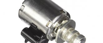
Trunk limit switch
Standardly, a limit switch is installed in the trunk to activate the backlight in it; on cars with a standard alarm system, it also serves to control opening during active security. The limit switch can also be used by the standard central locking, blocking locking if the trunk is not slammed shut.
If we are talking about a cheap car with a minimum configuration, then you will have to connect the trunk limit switch yourself when installing the alarm. It’s easiest for owners of those cars where more expensive equipment includes a standard trunk alarm switch: as with doors, here it is enough to install the original part in the designated place. Otherwise, alas, you will have to drill a hole and install a universal one. Increasingly, the switch is not installed as a separate part in the trunk, but is built into the lock itself, as is the case with the doors.
Sometimes this leads to serious problems: for example, on the Renault Koleos, a failure of the trunk locking mechanism has become a “trademark disease”, and in the author’s practice, the “anti-record” is only a week after purchasing a new car. The lock, not locking, did not allow the built-in limit switch to operate, and this, as on other cars on similar platforms, blocked the locking of the central locking as a whole; due to the non-locking trunk, the owner could not lock the doors. In such cases, it was necessary to tightly block the trunk lock in a locked state until a new one arrived for a warranty replacement.
RESPONSIBILITY
RESULTS ¸Ð½Ñип ÑабоÑÑ, коÑоÑÑй пÑÐ¸Ð²Ð¾Ð´Ð¸Ñ ÐµÐ³Ð¾ в движе ние. RESULTS µÐ¼Ñ конÑакÑа Ñ Ð¾Ð³Ñ°Ð½Ð¸ÑиÑелÑми. RESULTS » » »Response. RESULTS ROOM Ð ·Ð»Ð¾Ð¶ÐµÐ½Ð½Ñе задаÑи. RESULTS µÐ½Ð¸Ñ и конÑигÑÑаÑии конÑевÑÑ Ð²ÑклÑÑаÑелей. RESULTS ½ÑÑо ÑÑÑанавливаÑÑ Ð² оÑобо оп°Ñной зоне.
RESULTS ¼ ASSURANCE ¿Ð¾Ð ´Ð°ÑÑÑигнаÐ". RESULTS в ÑлекÑÑиÑеÑкой Ñепи. RESULTS ASSURANCE ÑиÑемой вÑклÑÑÐµÐ½Ð¸Ñ .
TYPES AND FIELD OF APPLICATION OF LIMIT SWITCHES
All devices of this type are conditionally divided into separate groups depending on:
- versions: open, closed and switchable;
- design and method of switching configuration: mechanical, non-contact and magnetic;
- dimensions and stroke length: standard and miniature.
The group of mechanical limit switches is represented by devices with rollers, sliders, levers or buttons. Single mechanical limit switches are rare; most often the units have a pair or more NO or NC electrical contacts with low switching current.
Despite the disadvantages associated with direct contact, they are cheap and are used in almost all areas of everyday life and production, including the automation of gates and industrial equipment.
Non-contact models are represented by inductive, optical (touch), capacitive and ultrasonic types of limit switches. The basis of their working unit is thyristors with low resistance, which change the state of the circuit when receiving a signal from sensitive elements.
They are used as volume and motion sensors and have a wide range of applications: from turning on the lights when opening doors and gate drives to the most accurate signaling devices in self-propelled guns.
Magnetic or reed switch types are recognized as optimal and practically independent of environmental conditions. Placing reed switches and a permanent magnet on moving and stationary parts allows you to quickly respond to changes in the distance between them; the connection diagram can be any.
Reed switches are successfully used when it is necessary to control and dosage liquid and bulk materials, automatically control gates, or activate an alarm when doors are opened.
In everyday life, limit switches are widely installed in sliding wardrobe doors, alarm and security systems for cars and houses, and gate control drives. In manufacturing, they are used in situations that require slowing down, switching windings, or completely stopping an automated electric drive.
A separate group includes rotary types of limit switches, equipped with cam mechanisms and connected to any motor or gearbox. They allow you to control the number of rotations or change the angle of movement with high precision, which is important for lifting equipment, conveyors, automatic gates and wind generators.
Areas of use
The possible area of application of induction sensors is so wide that it allows them to be used not only in everyday life and the automotive industry, but also in industry with robotics, as well as medicine.
Medical devices
Inductive sensors are widely used in the production of medical equipment, since the magnetic properties of the device make it possible to record pulmonary ventilation, vibration parameters, and also take ballistocardiograms.
Appliances
In everyday life, sensors can act as a device for monitoring water supply, lighting level and door position (closed or open), therefore they are used in the production of, for example, washing machines and other household appliances. In addition, the devices are used in the process of creating smart home elements.
Automotive industry
An induction sensor is also used in the automotive industry, acting as a controller that determines the position of the crankshaft. When a metal object, in this case a gear tooth, approaches the device, the magnetic field generated by the built-in permanent magnet increases, which leads to the induction of an alternating voltage in the coil.
Attention! Some manufacturers are trying to change the design of the induction sensor to increase efficiency, for example, using external magnets to activate it
Robotic equipment
In the case of robotics, inductive sensors have found application in the production of unmanned vehicles and industrial robots to increase their sensitivity to obstacles and the ability to recognize objects, as well as devices for which self-balancing is important.
Industrial control and measurement technology
They are widely used in the operation of conveyor systems, packaging machines and assembly lines, as well as as part of all types of machine tools and shut-off valves. Inductive sensors also help to monitor small and large elements of industrial equipment (gear teeth, steel flags, stamps), production objects (metal products, metal sheets, covers), etc. In addition, when connected to pulse counters, the result is a rudimentary but extremely effective reading device.
Application area
It is also necessary to know where limit switches are used. Each type of execution has its own specific purpose and is used in different fields of activity. However, according to their use they are divided into:
- Functional. They are responsible for regularly turning off or on the lighting, or some other electrical device. For example, such a device is located in the refrigerator. When the door opens, the mechanism turns on the light, and when it closes, it turns it off; this is one of the options for using a limit switch.
- Protective. They are installed in order to protect both the mechanism and workers from improper actions. For example, a miner's elevator will not begin to descend until the doors are closed, allowing people to use the elevator safely.
To summarize, the use of this device depends on the design and capabilities of the mechanism. Often, consumers do not know that they often have to use this mechanism in life:
- in the automotive industry and in the automobile;
- in household appliances and everyday life;
- in furniture products;
- in factories and manufacturing plants to carry out various tasks.
Limit switches are very practical and necessary devices. But to connect such devices, it is better to seek help from specialists. As has already become clear, these devices greatly simplify the use of many household items. We hope that the article provided was useful and interesting for you!
It will be useful to read:
- How to connect a changeover switch
- How to make an apron backlight in the kitchen
- How does a magnetic starter work?
https://youtube.com/watch?v=VuuRxGwi6mA
Modern analogues
In most cases, especially in everyday life, outdated switches are replaced with automatic protective devices. These substitutes are devices such as:
RCD and difavtomat
- RCD. The device is used to prevent current leakage. It is able to sense the differential current, which heats up the electrical wires, which contributes to a short circuit, and as a result, to the fire of the cables. In addition, overcurrents can kill a person. The RCD reacts to current leakage and de-energizes the power line when an emergency occurs. However, this device is not capable of protecting people and electrical equipment from short circuits and high loads unless a circuit breaker is installed with it.
- Circuit breaker. This is a real substitute for the device described. It is capable of performing the same tasks, but has a long service life, wear resistance, and ease of use. Automatic machines, like switches, have a polarity: single-pole, double-pole, three-pole and four-pole. Between themselves, automatic switches are divided into manual, spring and motor. In addition, they differ in the type of connection and other criteria.
- Differential automatic. A protective device that performs the functions of two devices - an RCD and an automatic device. This invention gained its popularity due to its small size and ease of use. It is able to prevent current leakage, prevent short circuits, and also reduce the risk of electric shock to a person. The machine has two releases: thermal - will protect against overloads in the circuit; electromagnetic - will de-energize the electrical network if a short circuit occurs.
- Contactor. The device is used to turn off and on the electrical network at a distance. This invention only works when the rated current is exceeded. It is not able to protect the electrical network from a short circuit. The devices are often installed in transport, in elevators, and also in production.
conclusions
Vacuum circuit breakers with rated voltages of 6, 10 and 35 kV are one of the most popular types of switching equipment for high-voltage networks today. They are more reliable in operation, durable and safe for operating personnel and the environment. Vacuum switches differ from other types of devices in their relatively simple and reliable structure. Therefore, this type of equipment serves for a long time without any complaints.
The natural wear life is determined by the number of operations equal to at least 20,000. Provided that maintenance is carried out in a timely manner, this life increases by 5-10%. Meanwhile, explosive maintenance is limited to a small number of light operations.