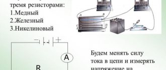
So, resistor... The basic element of constructing an electrical circuit.
The job of a resistor is to limit the current flowing through the circuit. NOT in converting current into heat, but in limiting current . That is, without a resistor current flows through the circuit ; if a resistor , the current decreased. This is its work, in which this element of the electrical circuit produces heat.
Example with a light bulb
Let's look at the operation of a resistor using the example of a light bulb in the diagram below. We have a power source, a light bulb, and an ammeter that measures the current passing through the circuit. And Resistor . When resistor in the circuit, a large current , for example, 0.75A. The light bulb burns brightly. They built a resistor into the circuit - the current had a difficult barrier to overcome; the current decreased to 0.2A. The light bulb burns less brightly. It is worth noting that the brightness with which the light bulb burns also depends on the voltage on it. The higher the voltage, the brighter it is.
Current limiting by resistor
In addition, a voltage drop occurs the resistor . The barrier not only delays the current , but also “eats” part of the voltage applied by the power source to the circuit. Consider this fall in the figure below. We have a 12 volt power supply. Just in case, an ammeter, two voltmeters in reserve, a light bulb and a resistor . We turn on the circuit without a resistor (left). The voltage at the light bulb is 12 volts. We connect the resistor - part of the voltage drops across it. The voltmeter (bottom right in the diagram) shows 5V. The remaining 12V-5V=7V remained for the light bulb. The voltmeter on the light bulb showed 7V.
Voltage drop across the resistor
Of course, both examples are abstract, imprecise in terms of numbers and are designed to explain the essence of the process occurring in a resistor .
The main characteristic of a resistor is resistance . The unit of resistance is Ohm (Ohm, Ω). The greater the resistance , the more current it can limit, the more heat it generates, the more voltage drops across it.
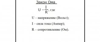
The fundamental law of all electricity. Connects Voltage (V), Current ( I) and Resistance (R).
V=I*R
These symbols can be interpreted in human language in different ways. The main thing is to be able to apply it for each specific circuit. Let's use Ohm's Law for our resistor and light bulb circuit discussed above and calculate the resistor's value that the current from a 12V power supply to 0.2. In this case, we assume the resistance of the light bulb to be 0.
V=I*R => R=V/I => R= 12V / 0.2A => R=60Ohm
So. If you integrate 60 Ohm resistor the current flowing through the circuit will be 0.2A.
Microproger, know and remember! resistor power parameter is one of the most important when constructing circuits for real devices.
The power of the electric current in any section of the circuit is equal to the product of the current flowing through this section and the voltage in this section of the circuit. P=I*U. The unit of measurement is 1W.
When current flows through a resistor, work is done to limit the electric current . When work is done, heat is released. The resistor dissipates this heat into the environment. But if the resistor does too much work and generates too much heat, it will no longer have time to dissipate the heat generated inside it, will heat up very much and burn out. What happens as a result of this incident depends on your personal luck quotient.
The power characteristic of a resistor is the maximum current power that it can withstand without overheating.
Let's calculate the resistor power for our circuit with a light bulb. So. We have a current passing through the circuit (and therefore through the resistor ) equal to 0.2A. The voltage drop across the resistor is 5V (not 12V, not 7V, but precisely 5 - the same 5 that the voltmeter shows on the resistor ). This means that current power through the resistor is P=I*V=0.2A*5V=1W. We conclude: the resistor for our circuit must have a maximum power of at least (or better, more) 1W. Otherwise it will overheat and fail.
What is the voltage drop across a resistor
Electric current passing through a circuit experiences resistance, which can change under the influence of various environmental conditions (extremely low temperatures or heat) and may depend on the characteristics of the particular conductor.
For example, the thinner the conductor or longer, the higher it is. The value of its value is influenced by the following factors:
- current strength;
- length of conductive parts;
- voltage;
- conductor element material;
- heating (temperature);
- cross-sectional area.
Resistors can be divided into constant, variable and trimming. Their main difference from each other is the ability to change the resistance indicator. The most common ones are fixed resistors - this indicator cannot be changed in them, which is why they got that name. Variables differ in that the resistance value in them can be adjusted. In a trimmer resistor it can also be changed, but the difference between this type is that it is not designed for frequent changes of the parameter. Trimmer resistors are made in a more compact package compared to variables.
To calculate the voltage drop across a resistor, you need to remember that the reduction in load applied to the entire circuit (that is, the voltage connected to the circuit) can be obtained both for the entire circuit and for any element in the circuit. The voltage is reduced due to the resistance that the conductors have.
The voltage drop across the resistor depends on the strength of the current passing and the characteristics of the conductors. Temperature and current readings also matter. For example, the voltage measured by a voltmeter on a light bulb connected to a 220 V network will be slightly lower due to the resistance that the light bulb has.
Power supplies have different voltage levels. This value may exceed what is needed at the output. To prevent the load that needs to be powered from burning out, it is often necessary to lower the voltage, including using resistors.
Voltage comparison table
| Power supply | Voltage |
| NiCd battery | 1.2 V |
| Lithium iron phosphate battery | 3.3 V |
| Battery type "Krona" | 9 V |
| Car battery | 12 V |
| Truck battery | 24 V |
In this case, the resistor should reduce the current flowing through the circuit. In this case, the current does not turn into heat, it is precisely its limitation that occurs. That is, when a resistor is connected to the circuit, the current will drop - this is the work of the resistor, during which the element heats up.
In general, voltage drops can be calculated using a simple formula that relates the indicators to each other.
But in some cases, for example, when connecting resistances in parallel, it is more difficult to calculate the required value. In this case, using a special formula, you will need to bring the resistance of parallel branches to one number:
R = R1*R2 / (R1+R2)
If necessary, other resistances that add up to this value are also taken into account (for example, resistance of the wire and power supply).
How to calculate complex resistor wiring diagrams
If you combine a larger number of elements, you need to add the required number of terms to the formulas considered.
READ MORE: Do-it-yourself wood milling machine step-by-step instructions
Initial data:
- DC source 12V;
- resistance of parallel resistors, Ohm: 10, 40, 60, 80.
Calculation:
- basic formula: 1/Req = 1/R1 1/R2 1/R3 1/R4;
- Substituting the initial data, calculate the conductivity: G = 1/Req = 1/10 1/40 1/60 1/80 = 0.1 0.025 0.0166 0.0125 = 0.1541;
- equivalent resistance: Req = 1/0.1541 ≈ 6.5 Ohm;
- current in the circuit: Itot = Uip/ Req = 12/ 6.5 ≈ 1.85 A.
Complex circuits
Using a similar technology, calculations are made for more complex circuits. The figure shows the resistance values. In both cases, the same power source is used with Uip = 12V.
Calculation 1 (serial and parallel connection):
- for each parallel section you can use the formula: Rtot = 1/ (1/R1 1/R2) = R1*R2/R1 R2;
- equivalent resistance of the first part: Req1 = (2*4)/ (2 4) = 1.3 Ohm;
- second: Req2 = (15*5)/ (15 5) = 3.75 Ohm;
- general: Req = 1.3 10 3.75 = 15.05 Ohm;
- Itot = Uip/ Req = 12/ 15.05 ≈ 0.8 A.
Calculation 2 (complex parallel connection):
- in this option, first calculate the conductivity of the part (R3, R4, R5) using the formula: G345 = 1/5 1/10 1/ 20 = 7/20 = 0.35 sim;
- Req (345) = 1/0.35 ≈ 2.857 Ohm;
- total value for the circuit: R1 R2 = 20 Ohm;
- By analogy with the previous method, they determine: G12345 = 0.4 sim and Req(12345) = (20*2.857)/ 20 2.857) ≈ 2.5 Ohm;
- after adding the last element (R6 = 7.5 Ohm), the final result is obtained: Req = 2.5 7.5 = 10 Ohm;
- division determines the current strength in the load connected to a 12 V current source: I = 12/10 = 1.2 A.
The last example uses an additional circuit component (R6). Accordingly, for this circuit the above-discussed proportion of equal voltages (source and connected load) will not be satisfied.
U6 = I *R6 = 1.2 * 7.5 = 9 V.
Uab = I * Reeq(12345) = 1.2*2.5 = 12-9 =3V.
The second part of the formula demonstrates the test by subtracting voltages (Uip - U6).
For ease of calculation, we first group the resistors by parallel and series connection types. Resistors R2 and R3 are connected in series (group 2). They, in turn, are connected in parallel with resistor R1 (group 1).
Calculation of more complex connections of resistors can be performed using Kirchhoff's laws.
Physical definition
A resistor is an element used in an electrical circuit and does not require a power source for its operation. It is designed to transform current into voltage and vice versa. In addition, it can convert electrical energy into thermal energy and limit the amount of current. But before calculating the voltage drop across a resistor, it is advisable to understand the essence of this process.
A resistor is a very common element characterized by a number of parameters. The main ones are:
- resistance;
- the amount of energy dissipated;
- operating voltage;
- power;
- resistance to environmental influences;
- parasitic component.
A passive electrical element is indicated in the diagram as a rectangle with two terminals from the middle of its sides. In the center of the figure, power can be indicated in Roman numerals or dashes. For example, a vertical stripe indicates the element's withstand power of 1 W. The crossed out rectangle in the notation in the diagram indicates that such a resistor is variable.
Resistors can be produced with constant and variable resistance. A type of the latter are tuning elements. The only difference between them and variables is the way they are set to the desired value.
On diagrams and in technical literature, the device is designated by the Latin letter R, next to which the serial number and its denomination are indicated in accordance with the International System of Units (SI). For example, R12 5 kOhm is a five kilo-ohm resistor located in the circuit under number 12.
When manufacturing an element, a resistive layer is used, which can be film or volumetric. It is applied to a dielectric base and covered with a protective film on top.
Resistance value
Resistance is a fundamental quantity in electrical processes. Its meaning is invariably related to current and voltage. Their general dependence is described using Ohm's law: the current strength arising in a section of the circuit is directly proportional to the potential difference between the extreme points of this section and inversely proportional to its resistance. From this law the resistance is found using the following formula:
R = U / I, where:
- R is the resistance in the circuit section, Ohm.
- I is the current strength passing through this section, A.
- U is the potential difference at the nodes of a part of the circuit, V.
In fact, the resistance of an element is determined by its physical structure and is caused by the vibrations of atoms in the crystal lattice. Therefore, all materials are classified as conductors, semiconductors and dielectrics depending on their ability to conduct electricity.
Current is the directed movement of charge carriers. For it to occur, the substance must have free electrons. If an electric field is applied to such a physical body, then the charges it moves will begin to collide with inhomogeneities in the structure. These defects are formed due to various impurities, violation of lattice periodicity, and thermal fluctuations. By hitting them, the electron expends energy, which is converted into heat. As a result, the charge loses momentum, and the magnitude of the potential difference decreases.
But Ohm's law cannot be applied to all substances. In electrolytes, dielectrics and semiconductors, a linear relationship between the three quantities is not always observed. The resistance of such substances depends on the physical parameters of the conductor, namely its length and cross-sectional area, and it is sensitive to temperature changes.
This dependence is described using the formula R = p * l / S. That is, the resistance is directly proportional to the length and inversely proportional to the area of the conductor. The value p is called resistivity and is determined by the type of material. Its meaning is taken from the reference book.
Resistor impedance
Ohm's law applies to an ideal resistor that has no parasitic resistance. The total resistance (impedance) is determined based on the equivalent circuit. Accurate calculation of resistance to reduce voltage must be carried out using other formulas. The equivalent circuit of a resistor, in addition to active impedance, also contains capacitive and inductive reactance.
The first leads to a slow accumulation of charge, which dissipates when the direction of the current changes. The larger the parasitic capacitance, the longer it takes to charge. Accordingly, the faster the current changes its direction, the lower its capacitance. The second is characterized by a magnetic field, whose appearance prevents the current from changing direction, therefore, the faster the current changes its movement, the greater the inductive reactance becomes.
Impedance is calculated using the formula: I = U/Z, where Z = (R2+(Xc-Xl)2)½. Where:
- R is the active value, R = p*l/s.
- Xc is a capacitive value, Xc = 1/w*C.
- Xl is an inductive quantity, Xl = w*C.
- w is the cyclic frequency, w = 2πƒ.
Knowing the total resistance of the resistor, you can more accurately calculate the voltage drop in it. But to measure parasitic components you will need to use highly specialized instruments. In conventional calculations, resistance is calculated taking into account only its active value, and parasitic values are taken as negligible.
Standard range of resistor powers and their designation in diagrams
Please note that resistors of the same value can have different power dissipations. This parameter depends on the manufacturing technology and case material. There is a certain number of capacities and their graphic designation according to GOST.
| W | Symbol not in diagrams |
| resistor power 0.05 W | How is the power dissipation of a 0.05 W resistor indicated in the diagram? |
| resistor power 0.125 W | Resistor power 0.125 W in the diagram |
| resistor power 0.025 W | What does a 0.25 W resistor look like in the diagram? |
| resistor power 0.5 W | This is how a 0.5 W resistor is indicated in the diagram. |
| resistor power 1 W | The power of a 1 W resistor is schematically indicated as follows |
| resistor power 2 W | Power dissipated by resistor 2 W |
| resistor power 5 W | Designation on the power diagram of a 5 W resistor |
The graphical designation of resistor power in the diagram is dashes and Roman numerals printed on the surface of the resistance. The smallest standard value is 0.05 W, the largest is 25 W, but there are also more powerful ones. But this is a special element base and is not found in household equipment.
You just need to remember how the power of low-power resistors is indicated. These are oblique lines on rectangles that represent resistance in diagrams. The number of slashes indicates the number of quarter inches. For resistance values of 1 W or more, Roman numerals are placed on the image: I, II, III, V, VI, etc. This figure indicates the power of the resistor in watts. It’s a little easier here, since the correspondence is direct.
Resistor power characteristic
The power of the electric current in a section of the circuit can be found through the product of the current strength for it and the voltage in this section. The formula is as follows: P= I * U (product of current and voltage), where
P – power value (W).
The resistor does work to reduce the current, while it releases heat into the surrounding space. But if the work to limit the current is very great and heat is generated too quickly, then it will overheat and may burn out, since it will not have time to dissipate it. This point should be taken into account when selecting the resistor power
Important! The power of a resistor is a very important parameter that must be taken into account when developing electrical circuits for devices. The power of a resistor is characterized by the maximum amount of current that it can withstand without overheating or failing.
Serial connection
This is the name for combining two or more resistors into one section of a circuit, in which their connection to each other occurs only at one point. Impedance when connected in series is defined as the sum of the resistances of each individual element: Rtotal = R1+R2+…+Rn.
Consequently, the current flowing through such a chain will become less and less after passing through a series-connected resistor. The more elements there are in the chain, the more difficult it will be for him to pass them all. Thus, its overall value is determined as Itotal = U / (R1+R2+…+Rn).
Therefore, it can be argued that in a series connection there is only one path for current to flow. The greater the number of resistors in the line, the less current will be in this section.
The drop in potential difference with this type of connection on each element will have its own meaning. It is determined by the formula URn = IRn*Rn, and the greater the impedance of the element, the more energy it will begin to release.
Useful tips Connection diagrams Principles of operation of devices Main concepts Meters from Energomer Precautions Incandescent lamps Video instructions for the master Testing with a multimeter
Voltage divider circuit using resistors
The voltage divider circuit includes an input voltage source and two resistors. Below you can see several schematic versions of the divider, but they all have the same functionality.
We recommend reading: Simple diagrams for beginner radio amateurs
Let's denote the resistor that is closer to the plus of the input voltage (Uin) as R1, and the resistor that is closer to the minus as R2. The voltage drop (Uout) across resistor R2 is the reduced voltage resulting from the use of a resistor voltage divider.
How to calculate resistance for voltage drop: resistor drop formula
A resistor is one of the most common elements in an electrical circuit. With its help, the current is limited and the voltage is changed. When designing circuits, you may often need to calculate the resistance to reduce the voltage. This is relevant when constructing dividers for digital devices or power supplies, so every radio amateur should be able to perform such calculations.
A resistor is an element used in an electrical circuit and does not require a power source for its operation. It is designed to transform current into voltage and vice versa. In addition, it can convert electrical energy into thermal energy and limit the amount of current. But before calculating the voltage drop across a resistor, it is advisable to understand the essence of this process.
A resistor is a very common element characterized by a number of parameters. The main ones are:
- resistance;
- the amount of energy dissipated;
- operating voltage;
- power;
- resistance to environmental influences;
- parasitic component.
A passive electrical element is indicated in the diagram as a rectangle with two terminals from the middle of its sides. In the center of the figure, power can be indicated in Roman numerals or dashes. For example, a vertical stripe indicates the element's withstand power of 1 W. The crossed out rectangle in the notation in the diagram indicates that such a resistor is variable.
Resistors can be produced with constant and variable resistance. A type of the latter are tuning elements. The only difference between them and variables is the way they are set to the desired value.
On diagrams and in technical literature, the device is designated by the Latin letter R, next to which the serial number and its denomination are indicated in accordance with the International System of Units (SI). For example, R12 5 kOhm is a five kilo-ohm resistor located in the circuit under number 12.
When manufacturing an element, a resistive layer is used, which can be film or volumetric. It is applied to a dielectric base and covered with a protective film on top.
Resistance value
Resistance is a fundamental quantity in electrical processes. Its meaning is invariably related to current and voltage. Their general dependence is described using Ohm's law: the current strength arising in a section of the circuit is directly proportional to the potential difference between the extreme points of this section and inversely proportional to its resistance. From this law the resistance is found using the following formula:
R = U / I, where:
- R is the resistance in the circuit section, Ohm.
- I is the current strength passing through this section, A.
- U is the potential difference at the nodes of a part of the circuit, V.
In fact, the resistance of an element is determined by its physical structure and is caused by the vibrations of atoms in the crystal lattice. Therefore, all materials are classified as conductors, semiconductors and dielectrics depending on their ability to conduct electricity.
Current is the directed movement of charge carriers. For it to occur, the substance must have free electrons. If an electric field is applied to such a physical body, then the charges it moves will begin to collide with inhomogeneities in the structure. These defects are formed due to various impurities, violation of lattice periodicity, and thermal fluctuations. By hitting them, the electron expends energy, which is converted into heat. As a result, the charge loses momentum, and the magnitude of the potential difference decreases.
But Ohm's law cannot be applied to all substances. In electrolytes, dielectrics and semiconductors, a linear relationship between the three quantities is not always observed. The resistance of such substances depends on the physical parameters of the conductor, namely its length and cross-sectional area, and it is sensitive to temperature changes.
This dependence is described using the formula R = p * l / S. That is, the resistance is directly proportional to the length and inversely proportional to the area of the conductor. The value p is called resistivity and is determined by the type of material. Its meaning is taken from the reference book.
Resistor impedance
Ohm's law applies to an ideal resistor that has no parasitic resistance. The total resistance (impedance) is determined based on the equivalent circuit. Accurate calculation of resistance to reduce voltage must be carried out using other formulas. The equivalent circuit of a resistor, in addition to active impedance, also contains capacitive and inductive reactance.
The first leads to a slow accumulation of charge, which dissipates when the direction of the current changes. The larger the parasitic capacitance, the longer it takes to charge. Accordingly, the faster the current changes its direction, the lower its capacitance. The second is characterized by a magnetic field, whose appearance prevents the current from changing direction, therefore, the faster the current changes its movement, the greater the inductive reactance becomes.
Impedance is calculated using the formula: I = U/Z, where Z = (R2+(Xc-Xl)2)½. Where:
- R is the active value, R = p*l/s.
- Xc is a capacitive value, Xc = 1/w*C.
- Xl is an inductive quantity, Xl = w*C.
- w is the cyclic frequency, w = 2πƒ.
Knowing the total resistance of the resistor, you can more accurately calculate the voltage drop in it. But to measure parasitic components you will need to use highly specialized instruments. In conventional calculations, resistance is calculated taking into account only its active value, and parasitic values are taken as negligible.
Parallel connection
Electrical circuits use both parallel and series connections in sections of the circuit. The first is a circuit in which each element is connected to the other by both contacts, but there is no direct electrical connection between its own terminals. That is, there are two points (electrical nodes) to which several resistors are connected.
With this switching on, the current passing through the node begins to split, and a different value will flow through each element. The amount of current in each element will be directly proportional to the resistance of the resistor, so the total conductivity in this section will increase, and its impedance will decrease.
The formula with which you can calculate the total conductivity looks like this: G = 1/ Rtot = 1/ R1 + 1/ R2 +…+ 1/ Rn, where n denotes the serial number of the resistor in the circuit.
Transforming this formula, you get an expression of the form: R total = 1/G = (R1*R2*…* Rn) / (R1*R2 + R2*Rn +…+ R1*Rn. Having analyzed it, we can conclude that with parallel connection, the impedance will always be less than the smallest value of an individual resistor.
With such a connection, the voltage between the nodes is simultaneously the total potential difference for the entire section and at each individual resistor. Therefore, if you calculate the voltage drop on one device, then it will be the same on any parallel-connected element: U total = U 1 = U 2 =...= U n.
But the electric current passing through a separate element, based on Ohm’s law, will be equal to: I Rn = U Rn / R n.
Serial connection
This is the name for combining two or more resistors into one section of a circuit, in which their connection to each other occurs only at one point. Impedance when connected in series is defined as the sum of the resistances of each individual element: Rtotal = R1+R2+…+Rn.
Consequently, the current flowing through such a chain will become less and less after passing through a series-connected resistor. The more elements there are in the chain, the more difficult it will be for him to pass them all. Thus, its overall value is determined as Itotal = U / (R1+R2+…+Rn).
Therefore, it can be argued that in a series connection there is only one path for current to flow. The greater the number of resistors in the line, the less current will be in this section.
We recommend reading: Starter (contactor) connection diagram: how to do it yourself
The drop in potential difference with this type of connection on each element will have its own meaning. It is determined by the formula URn = IRn*Rn, and the greater the impedance of the element, the more energy it will begin to release.
Voltage divider calculation
A resistive voltage divider represents a basic circuit for reducing voltage. It can consist of two or more elements. The simplest divider can be represented as two sections of the chain, which are called shoulders. One of them, which is located between the positive and zero potential points, is the upper one, and the other, between the negative and minus ones, is the lower one.
This circuit is used to reduce voltage in both constant and variable circuits. The essence of the process is as follows.
- The resistive circuit is supplied with voltage U from the power source.
- Current begins to flow through the resistors of the series section of the circuit formed by resistors R1 and R2.
- As a result, a certain amount of energy is released at each of them, i.e., a voltage drop occurs.
The sum of the voltages across the entire line span is equal to the potential difference of the power source. In accordance with the formula: U = I*R, the voltage drop is directly proportional to the current strength and resistance value. Considering that the current flowing through the resistors is the same, the formulas U1 = I*R1 and U2= I*R2 will be valid.
Then the total voltage drop in the section will be equal to U = I * (R1+ R2). Based on this, you can find the current strength: I = U / (R1+ R2). Using these two expressions, the final formulas for calculating the voltage drop across each element can be obtained:
- U1 = R1*U/(R1+R2);
- U2 = R2*U/(R1+R2).
The practical use of such a divider is very common due to the ease of implementing voltage reduction. For example, let the power supply supply 12 V, and the load needs to be supplied with 6 V, while its resistance is 10 kOhm. To solve this problem, it is recommended to use resistors whose resistance is ten times less than the load value, therefore, taking R 1 = 1 kOhm and substituting all known values into the voltage formula on the resistor, it turns out that 6 = R 2 * 12 (1000+ R 2 ) hence R 2 = 1 kOhm.
Now, knowing all the values, you can check the accuracy of the calculation. The potential difference drop across the first element is calculated as U 1 = 1000*12/(1000+1000) = 6 V, and the total voltage is Utot = U 1+ U 2 = 12 V, which corresponds to the value of the power source.
It should be noted that the use of pull-down resistors is only used for low-power loads, since some of the energy is converted into heat and the coefficient of performance (COP) is very low.
Mixed connection of resistors in a circuit
Other connection methods are clear from the examples shown in the picture. Without special calculations, it is clear that parallel connection of resistors creates several current paths. Consequently, in individual circuits its strength will be less compared to the control points at the input and output. However, the voltage in the marked places remains unchanged.
Connecting resistors in series increases the overall electrical resistance. The current in this circuit (based on basic principles) will not change. However, at each passive element the corresponding voltage drop can be detected by the measuring instrument.
Rtotal = R1 R2 … Rn.
Regardless of the complexity of the circuit, the currents at the input and output will be the same according to Kirchhoff’s first law.
Consider an electrical circuit in which three resistors are located in series, i.e. one after another. Their total resistance (R) will be the sum of the resistances of an individual resistor (r).
To illustrate the example, let’s consider ordinary 40 W incandescent lamps as resistors. In this case, the tungsten filament has its own resistance and can be considered a resistor. We will also introduce the concept of load power or resistor (P), which is measured in watts (W).
It has a linear dependence on current and voltage and is calculated by the formula: P=IxU. Using simple calculations, we can find the current strength in the resistor, which is the light bulb.
Current (I) = Lamp power (P) / Voltage (U) = 40 W / 220 V = 0.1818 A.
For a series connection of elements in an electrical circuit, the rule is that the current flowing through all conductors is the same. Thus, the current in resistor r2 or r3 will also be 0.1818 A. But in our version with light bulbs, one feature will be noted - the brightness of the glow will decrease.
This occurs because the resistor acts as a voltage divider. This nuance is often used to extend the life of non-critical devices. For example, by soldering a resistance in front of a light bulb, you can extend its service life, but you will have to cope with the lack of illumination.
In their pure form, parallel and series circuits are extremely rare in electrical engineering. As a rule, there is a combination of them. In order to find the current strength in each resistor with a mixed connection, it is necessary to divide the circuit into sections. Thus, when placing elements after each other, the so-called. "cascade", the rules and formulas for serial connection are applied.
Results of measuring current in a resistor. Various types of resistors.
It should be noted that to simplify calculations, parallel resistors can be grouped. When calculating the current strength in a certain area, they are taken as an independent element. Accordingly, in this case, the formulas are used as for calculating parameters for a parallel connection.
The algorithm for calculating mixed connections is based on the same rules as in elementary circuits for calculating series and parallel connections of resistors. There is nothing new: you need to correctly divide the proposed scheme into sections suitable for calculation. Sections with elements are connected alternately or in parallel.
READ MORE: Father built a playhouse for his son with his own hands, evaluate what happened Detailed instructions with photos can be done by everyone
To solve the problem of serial and parallel connection of resistors, it is necessary to correctly evaluate the circuits of the elements. The diagram shows a parallel and serial part of the connection of elements. For calculations, it is very important to simplify the circuits carefully, step by step, and not take the entire circuit at once (Fig. 1). How to correctly determine the parallel and series connection of resistors?
For an example of calculation, let's take resistors R3, R4, which are connected in parallel. The equivalent resistor of these elements will be equal to Re. = 1/R34 =1/R3 1/R4, after transforming the formula and bringing it to one denominator, we get R34 = R3 · R4 / (R3 R4). E. = 1/3 1/4 /(3 4) = 1.7 Ohm.
It is further seen that the given equivalent R eq and R6 are connected in series, to find out the resistance they must be added, then the total resistance will be equal to R346 = R34 R6, then R eq346 = 1.7 6 = 7.7 Ohms.
We replace it in the diagram with one common element, now the position is simplified even more. Now a situation has arisen - the inclusion of three elements in //. We already know how such a connection is calculated, 1/ R23465 = 1/ R2 1/R346 1/R5 after calculating the right side we get 0.82 Ohm. After the final calculation we get R23465 = 2.1 Ohm.
When the receivers are connected in parallel, they are all under the same voltage, and the operating mode of each of them does not depend on the others. This means that the current passing through any of the receivers will not have a significant effect on the other receivers. Whenever any receiver is turned off or fails, the remaining receivers remain on.
Therefore, a parallel connection has significant advantages over a serial connection, as a result of which it is most widely used. In particular, electric lamps and motors designed to operate at a certain (rated) voltage are always connected in parallel. On DC electric locomotives and some diesel locomotives, traction motors must be switched on at different voltages during speed control, so they switch from a series connection to a parallel connection during acceleration.
It may be easier for you if you know that by connecting two identical resistors in parallel, the result will be half as large. For example, by connecting two 100 Ohm resistors in parallel, we get a composite resistance of 50 Ohms. Shall we check? We count: 100*100 / (100 100) = 10000 / 200 = 50 Ohm.
Let's first calculate the parallel connection of two resistors of different values and see what happens.
- Connected in parallel 150 Ohm and 100 Ohm. We calculate the result: 150*100 / (150 100) = 15000/250 = 60 Ohm.
- If we connect 150 Ohms and 50 Ohms, we get: 150*50 / (150 50) = 7500 / 200 = 37.5 Ohms.
As you can see, in both cases the result is less than the lowest value of the connected parts. This is what is used if there is no small nominal resistance available. The only problem is that it’s difficult to select: you have to calculate using a calculator every time.
Types of connections.
Determining the current strength across a resistor for different types of connection
The easiest way to determine the current in a resistor is to use a multimeter. The measurement is carried out in the open circuit after the resistor. The maximum range of values is set on the tester, and the probes of the device are connected to the place where the conductor is disconnected. The multimeter display will show the results of measuring the current in the resistor. I = U/R, where we have I – current, U – voltage, R – resistance.
In the SI system, these quantities are measured in amperes (A), volts (V), ohms (Ohm), respectively.
By substituting the required values into the formula, you can determine the resistance, voltage and current on a resistor or any section or element of an electrical circuit.
How to choose a replacement resistor
If you need to change a resistor, you need to take either the same power or higher. In no case lower - after all, the resistor is already out of order. This usually happens due to overheating. So installing a lower power resistor is excluded. Or rather, you can install it. But be prepared for the fact that you will have to change it again soon.
You can roughly determine the resistor power by size
If space on the board allows, it is better to install a part with greater power dissipation than that of the part being replaced. Or raise the resistor of the same power higher (you don’t have to cut the leads at all) - for better cooling. In general, when replacing a resistor, take the power either the same or one step higher.
How to lower voltage using a resistor
To prevent the load that needs to be powered from burning out, it is often necessary to reduce the input voltage. The easiest way to achieve this is to use a two-resistor circuit, better known as a voltage divider. The classic scheme looks like this:
In this case, the voltage is supplied to two resistors using a parallel connection, and at the output it is received from one. The selection of resistor values is carried out according to the formula so that the voltage removed at the output is some part of the supplied one. You can calculate a resistor to reduce the voltage using a formula based on Ohm's law:
Uout= (Uin*R2)/(R1+R2), where
Uin – input voltage, V;
Uout – output voltage, V
R1 – resistance index. 1st resistor (Ohm)
R2 – resistance index. 2nd element, (Ohm)
Selecting a resistor to reduce voltage
To select the required resistor resistance, you can use ready-made online calculators or programs for simulating the operation of electronic circuits. Electrical circuit simulators are capable of not only calculating the output voltage depending on the resistance of the elements and the method of their connection, but also have functionality that allows you to visualize how the current and voltage across the resistor drops. For example, the EveryCircuit application allows you to change the parameters of elements in the circuit, select the simulation speed, and obtain data at various points. In this case, you can observe the dynamics of changes in values using the rotating dial in the lower right corner to enter input parameters.
There are also a number of free emulation programs that allow you to perform, among other things, calculations of a resistor when the voltage drops, for example:
- EasyEDA;
- Circuit Sims;
- DcAcLab;
and others.
In the article, we became acquainted with the concept of resistance, learned about its units of measurement, the marking of resistors, programs that emulate the operation of a circuit and facilitate the selection of the desired resistance, and also looked at examples of calculating the voltage drop across a resistor.
How to determine by appearance
The circuit diagram shows the required resistor power - everything is clear here. But how can you determine the resistance power by its appearance on the printed circuit board? In general, the larger the case size, the more heat it dissipates. On fairly large resistances, the nominal resistance and its power in watts are indicated.
There is some confusion here, but it's not all that bad. On domestic resistances they put the letter B next to the number. In foreign ones they put W. But these letters are not always there. In imported ones there may be a V or SW before the number. Imported ones may also have the letter B, but domestic MLTs may have nothing or the letter W. A confusing story, of course. But with experience, at least some clarity appears.
How to determine the power of a resistor: it is marked
But there are small resistors on which even the nominal value can hardly fit. In imported ones it is applied with colored stripes. How can you find out their dissipation power?
In the old GOST there was a table of correspondence between sizes and capacities. Domestic resistors are still made in accordance with this table. By the way, there are also imported ones, but they are slightly smaller in size than domestic ones. However, they can also be identified. If you are in doubt about which group a particular specimen belongs to, it is better to assume that it has a lower ability to dissipate heat. There is less chance that the part will burn out soon.
| Resistor type | Diameter, mm | Length, mm | Power dissipation, W |
| Sun | 2,5 | 7,0 | 0,125 |
| ULM, VS | 5,5 | 16,5 | 0,25 |
| Sun | 5,5 | 26,5 | 0,5 |
| 7,6 | 30,5 | 1 | |
| 9,8 | 48,5 | 2 | |
| 25 | 75 | 5 | |
| 30 | 120 | 10 | |
| CMM | 1,8 | 3,8 | 0,05 |
| 2,5 | 8 | 0,125 | |
| MLT | 2 | 6 | 0,125 |
| 3 | 7 | 0,125 | |
| 4,2 | 10,8 | 0,5 | |
| 6,6 | 13 | 1 | |
| 8,6 | 18,5 | 2 |
It seems clear with the sizes of the resistances and their power. Not everything is so simple. There are large resistors with low dissipation capacity and vice versa. But in such cases, this parameter is indicated in the labeling.
Power of SMD resistors
SMD components are designed for surface mounting and have miniature dimensions. The power of SMD resistors is determined by size. It is also in the specifications, but you need to know the series and manufacturer. The power table for SMD resistors contains the most common values.
The dimensions of SMD resistors - this is how you can determine the power of these elements
| Code imperial | Metric code | Length inch/mm | Width inch/mm | Height inch/mm | Power, W |
| 0201 | 0603 | 0,024/0,6 | 0,012/0,3 | 0,01/0,25 | 1/20 (0,05) |
| 0402 | 1005 | 0,04/1,0 | 0,02/0,5 | 0,014/0,35 | 1/16 (0,062) |
| 0603 | 1608 | 0,06/1,55 | 0,03/0,85 | 0,018/0,45 | 1/10 (0,10) |
| 0805 | 2112 | 0,08/2,0 | 0,05/1,2 | 0,018/0,45 | 1/8 (0,125) |
| 1206 | 3216 | 0,12/3,2 | 0,06/1,6 | 0,022/0,55 | 1/4 (0,25) |
| 1210 | 3225 | 0,12/3,2 | 0,10/2,5 | 0,022/0,55 | 1/2 (0,50) |
| 1218 | 3246 | 0,12/3,2 | 0,18/4,6 | 0,022/0,55 | 1,0 |
| 2010 | 5025 | 0,20/2,0 | 0,10/2,5 | 0,024/0,6 | 3/4 (0,75) |
| 2512 | 6332 | 0,25/6,3 | 0,12/3,2 | 0,024/0,6 | 1,0 |
In general, this type of radio elements has no other operational way of determining the current at which they can operate, other than by size. You can recognize them by their characteristics, but finding them is not always easy.
What is the voltage after the resistor
There is another way to reduce the voltage across the load, but only for DC circuits. See about it here.
Instead of an additional resistor, a chain of diodes connected in series in the forward direction is used.
The whole point is that when current flows through the diode, a “forward voltage” drops across it, equal to, depending on the type of diode, power and current flowing through it, from 0.5 to 1.2 Volts.
On a germanium diode the voltage drops 0.5 - 0.7 V, on a silicon diode from 0.6 to 1.2 Volts. Based on how many volts you need to reduce the voltage at the load, turn on the appropriate number of diodes.
To lower the voltage by 6 V, you need to approximately turn on: 6 V: 1.0 = 6 pieces of silicon diodes, 6 V: 0.6 = 10 pieces of germanium diodes. The most popular and accessible are silicon diodes.
The above circuit with diodes is more cumbersome to implement than with a simple resistor. But the output voltage in a circuit with diodes is more stable and weakly dependent on the load. What is the difference between these two methods of reducing the output voltage?
A resistor (wire resistance) has a linear relationship between the current passing through it and the voltage drop across it. By how many times the current increases, the voltage drop across the resistor will increase by the same amount.
From example 1: if we connect another one in parallel to a light bulb, the current in the circuit will increase, taking into account the total resistance of the two light bulbs to 0.66 A. The voltage drop across the additional resistor will be: 12 Ohm * 0.66 A = 7.92 V The light bulbs will remain: 12 V - 7.92 V = 4.08 V. They will burn at half incandescence.
A completely different picture will be if instead of a resistor there is a chain of diodes.
The relationship between the current flowing through the diode and the voltage dropped across it is nonlinear. The current can increase several times, the voltage drop across the diode will increase by only a few tenths of a volt.
Those. The greater the diode current, the less (compared to a resistor) its resistance increases. The voltage drop across the diodes depends little on the current in the circuit.
Diodes in such a circuit act as a voltage stabilizer. Diodes must be selected according to the maximum current in the circuit. The maximum permissible current of the diodes must be greater than the current in the circuit being calculated.
The voltage drops on some diodes at a current of 0.5 A are given in the table.
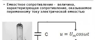
In AC circuits, a capacitor, inductance, dynistor or thyristor (with the addition of a control circuit) can be used as additional resistance.
For a person who is familiar with electrical equipment at the level of a simple user (knows where and how to turn it on/off), many of the terms used by electricians seem like some kind of nonsense. For example, what does “voltage drop” or “circuit assembly” cost? Where and what falls? Who took the circuit apart? In fact, the physical meaning of the processes occurring, hidden behind most of these words, is quite understandable even with school knowledge of physics.
We recommend reading: DIY FM antenna for a music center
To explain what a voltage drop is, it is necessary to remember what kind of voltages there are in general (this refers to the global classification). There are only two types. The first is the voltage that is connected to the circuit in question. It may also be said to be applied to the entire circuit. And the second type is precisely the voltage drop. It can be considered both in relation to the entire contour and any individual element.
In practice it looks like this. For example, if you take a regular one, screw it into a socket, and connect the wires from it to a home power outlet, then the voltage applied to the circuit (power source - conductors - load) will be 220 Volts. But as soon as we measure its value on the lamp using a voltmeter, it will become obvious that it is slightly less than 220. This happened because there was a voltage drop across the lamp.
There is probably no person who has not heard of Ohm's law. In general, its formulation looks like this:
where R is the active resistance of the circuit or its element, measured in Ohms; U - electrical voltage, in Volts; and finally, I is the current in Amperes. As you can see, all three quantities are directly related to each other. Therefore, knowing any two, you can quite simply calculate the third. Of course, in each specific case you will have to take into account the type of current (alternating or direct) and some other clarifying characteristics, but the basis is the above formula.
Electrical energy is, in fact, the movement of negatively charged particles (electrons) along a conductor. In our example, the lamp filament has high resistance, that is, it slows down moving electrons.
Due to this, a visible glow appears, but the overall energy of the particle flow is reduced. As can be seen from the formula, as the current decreases, the voltage also decreases. That is why the measurement results at the outlet and at the lamp differ. This difference is the voltage drop.
This value is always taken into account to prevent too much reduction on the elements at the end of the circuit.
The voltage drop across a resistor depends on it and the strength of the current flowing through it. Temperature and current characteristics also have an indirect effect. If an ammeter is included in the circuit under consideration, then the drop can be determined by multiplying the current value by the lamp resistance.
But it is not always possible to calculate the voltage drop so simply using a simple formula and a measuring instrument. In the case of parallel connected resistances, finding the value becomes more complicated. We have to additionally take into account the reactive component.
Let's consider an example with two resistors R1 and R2 connected in parallel. The resistance of the wire R3 and the power supply R0 is known. The value of EMF is also given - E.
We bring parallel branches to one number. For this situation, the formula applies:
R = (R1*R2) / (R1+R2)
We determine the resistance of the entire circuit through the sum R4 = R+R3.
We calculate the current:
It remains to find out the value of the voltage drop across the selected element:
Here the multiplier “R5” can be any R - from 1 to 4, depending on which particular circuit element needs to be calculated.
So, a resistor... The basic element of constructing an electrical circuit.
The job of a resistor is to limit the current flowing through the circuit. NOT in converting current into heat, but in limiting the current. That is, without a resistor, a large current flows through the circuit; if a resistor was built in, the current decreased. This is its work, in which this element of the electrical circuit produces heat.
Example with a light bulb
Let's look at the operation of a resistor using the example of a light bulb in the diagram below. We have a power source, a light bulb, and an ammeter that measures the current passing through the circuit. And Resistor. When there is no resistor in the circuit, a large current, for example, 0.75A, will flow through the light bulb along the circuit.
The light bulb burns brightly. They built a resistor into the circuit - the current had a difficult barrier to overcome; the current flowing through the circuit decreased to 0.2A. The light bulb burns less brightly. It is worth noting that the brightness with which the light bulb burns also depends on the voltage on it. The higher the voltage, the brighter it is.
In addition, a voltage drop occurs across the resistor. The barrier not only delays the current, but also “eats” part of the voltage applied by the power source to the circuit. Consider this fall in the figure below. We have a 12 volt power supply.
Just in case, an ammeter, two voltmeters in reserve, a light bulb and a resistor. We turn on the circuit without a resistor (on the left). The voltage at the light bulb is 12 volts. We connect the resistor - part of the voltage drops across it. The voltmeter (bottom right in the diagram) shows 5V.
The remaining 12V-5V=7V remained for the light bulb. The voltmeter on the light bulb showed 7V.
Of course, both examples are abstract, imprecise in terms of numbers and are designed to explain the essence of the process occurring in the resistor.
Resistor resistance unit
The main characteristic of a resistor is resistance. The unit of resistance is Ohm (Ohm, Ω). The greater the resistance, the more current it can limit, the more heat it generates, the more voltage drops across it.
Ohm's law for an electrical circuit
The fundamental law of all electricity. Connects Voltage (V), Current (I) and Resistance (R).
These symbols can be interpreted in human language in different ways. The main thing is to be able to apply it for each specific circuit. Let's use Ohm's Law for our resistor and light bulb circuit discussed above and calculate the resistance of the resistor that will limit the current from the 12V power supply to 0.2. In this case, we assume the resistance of the light bulb to be 0.
V=I*R => R=V/I => R= 12V / 0.2A => R=60Ohm
So. If you integrate a 60 Ohm resistor into a circuit with a power source and a light bulb whose resistance is 0, then the current flowing through the circuit will be 0.2A.
Resistor power characteristic
Microproger, know and remember! The resistor power parameter is one of the most important when constructing circuits for real devices.
The power of the electric current in any section of the circuit is equal to the product of the current flowing through this section and the voltage in this section of the circuit. P=I*U. The unit of measurement is 1W.
When current flows through a resistor, work is done to limit the electric current. When work is done, heat is released. The resistor dissipates this heat into the environment. But if the resistor does too much work and generates too much heat, it will no longer have time to dissipate the heat generated inside it, will heat up very much and burn out. What happens as a result of this incident depends on your personal luck quotient.
The power characteristic of a resistor is the maximum current power that it can withstand without overheating.
Resistor power calculation
Let's calculate the resistor power for our circuit with a light bulb. So. We have a current passing through the circuit (and therefore through the resistor) equal to 0.2A.
The voltage drop across the resistor is 5V (not 12V, not 7V, but precisely 5 - the same 5 that the voltmeter shows on the resistor). This means that the current power through the resistor is P=I*V=0.2A*5V=1W.
We conclude: the resistor for our circuit must have a maximum power of at least (or better, more) 1W. Otherwise it will overheat and fail.
Current flowing in a circuit of parallel connected resistors
When considering the corresponding sections of branched circuits, it is necessary to remember that the currents at the input and output of each node are equal, as well as before and after the group of parallel resistors. This rule will help check the correctness of the calculations. If the marked correspondence is not met, the calculation error is eliminated.
Using the initial data discussed above for two complex circuits, a calculation can be made for each individual branch.
Example 1:
- the total current in the circuit is 0.8 A;
- the distribution of voltages in individual sections is easy to determine from the calculated equivalent resistances: U12 = I * Req1 = 0.8 * (2*4)/ (2 4) = 0.8 * 1.3 = 1.04 V;
- The current values are calculated using the standard algorithm: I1 = U12/R1 = 0.52 A, I2 = U12/R2 = 0.26 A;
- summation checks the correctness of the calculations: I = I1 I2 = 0.52 0.26 ≈ 0.8 A.
Example 2 (mixed method of connecting resistors):
- current in this version is 1.2 A;
- the voltage in the section with a group of parallel resistors is Uab = I * Reeq(12345) = 1.2*2.5 = 3V;
- By analogy with the previous example, it is easy to calculate the current in each individual branch: I12 = Uav/(R1 R2) = 3/ (15 5) = 0.15 A;
- I3 = Uav/ R3 = 3/ 5 = 0.6 A;
- I4 = Uav/ R4 = 3/ 10 = 0.3 A;
- I5 = Uav/ R5 = 3/20 = 0.15 A;
- According to the rule of equality of currents at the input and output of the node, the correctness of the calculations made is checked: I = I12 I3 I4 I5 = 0.15 0.6 0.3 0.15 = 1.2 A.
READ MORE: Active and reactive resistance
P = I2 *R = U2/ R.
For your information. The design of each element is designed for a specific operating temperature range. Exceeding the threshold can destroy the part, the soldering point, and neighboring components. One should not forget about a simultaneous significant change in resistance, which can disrupt the functional state of the electrical circuit.
For the calculation, select a suitable formula taking into account the known initial parameters (data from example 2 in the previous section):
- current – 1.2 A;
- at resistance R6=7.5 Ohm the power dissipation will be: P6 = I2 *R = 1.44 * 7.5 = 10.8 W;
- It is difficult to find such a resistor, since the standard range offers ratings from 0.05 to 5 W;
- in another circuit (R5=20 Ohm) the calculated current will be 0.15 A, so P5= 0.0225 * 20 = 0.45 W;
- in this case, you can choose a product with a suitable dissipation power in the standard range of 0.5 W (experts recommend making a 1.52-fold margin, so it is better to use a 1 W resistor).
Standard symbols on electrical diagrams and typical power ratings
For your information. When choosing resistors, you should take into account the product class in terms of electrical resistance accuracy. In serial parts, deviations of 5-20% are acceptable.
Select the appropriate option (combination) taking into account the available initial data. It should be remembered that there is a single voltage at the input and output and different currents in individual branches. Computing technology is discussed in previous sections.
The total current I flowing in a circuit of parallel resistors is equal to the sum of the individual currents flowing in all parallel branches, and the current in a single branch does not necessarily have to be equal to the current in adjacent branches.
Despite the parallel connection, the same voltage is applied to each resistor. And since the value of resistance in a parallel circuit can be different, the amount of current flowing through each resistor will also be different (as defined by Ohm’s law).
Let's consider this using the example of two resistors connected in parallel. The current that flows through each of the resistors (I1 and I2) will be different from each other since the resistances of resistors R1 and R2 are not equal. However, we know that the current that enters the circuit at point "A" must leave the circuit at point " B"
I = I1 I2
Current flowing in R1 = U ÷ R1 = 12 ÷ 22 kOhm = 0.545 mA
Current flowing in R 2 = U ÷ R2 = 12 ÷ 47 kOhm = 0.255 mA
I = 0.545 mA 0.255 mA = 0.8 mA
I = U ÷ R = 12 V ÷ 15 kOhm = 0.8 mA (same)
where 15 kOhm is the total resistance of two parallel connected resistors (22 kOhm and 47 kOhm)
And in conclusion, I would like to note that most modern resistors are marked with colored stripes and their purpose can be found out here.