One of the main devices in electronics and electrical engineering is a capacitor. After closing the electrical circuit, charging begins, after which it immediately becomes a source of current and voltage, and an electromotive force arises in it - EMF. One of the main properties of a capacitor is very accurately reflected by the capacitance formula. This phenomenon occurs as a result of counter-EMF directed against the current source used for charging. The current source can overcome capacitance only by significant expenditure of its own energy, which becomes the energy of the electric field of the capacitor.
When the device discharges, all this energy is returned back to the circuit, turning into electrical energy. Therefore, capacitance can be classified as reactive, which does not cause irreversible energy losses. The capacitor is charged to the voltage level supplied by the power source.
Capacitance of a capacitor
Capacitors are among the most common elements used in various electronic circuits. They are divided into types that have characteristic features, parameters and individual properties. The simplest capacitor consists of two metal plates - electrodes, separated by a dielectric layer. Each of them has its own terminal through which the connection to the electrical circuit is made.
There are qualities unique to capacitors. For example, they do not allow direct current to pass through them at all, although they are charged by it. After the container is fully charged, the current flow stops completely, and the internal resistance of the device takes on an infinitely high value.
In a completely different way, the capacitor is affected by alternating current, which flows quite freely through the capacitance. This condition is explained by the constant processes of charging and discharging the element. In this case, not only the active resistance of the conductors acts, but also the capacitive reactance of the capacitor itself, which arises precisely as a result of its constant charging and discharging.
The electrical parameters and properties of capacitors may vary depending on various factors. First of all, they depend on the size and shape of the product, as well as on the type of dielectric. In different types of devices, the dielectric can be paper, air, plastic, glass, mica, ceramics and other materials. Electrolytic capacitors use aluminum electrolyte and tantalum electrolyte, which provides them with increased capacity.
The names of other elements are determined by the materials of conventional dielectrics. Therefore, they fall into the category of paper, ceramic, glass, etc. Each of them, in accordance with the characteristics and features, is used in specific electronic circuits, with different electric current parameters.
In this regard, the use of ceramic capacitors is necessary in those circuits where high-frequency noise filtering is required. Electrolytic devices, on the other hand, filter out interference at low frequencies. If you connect both types of capacitors in parallel, you get a universal filter that is widely used in all circuits. Despite the fact that their capacitance is a fixed value, there are devices with variable capacitance, which is achieved by adjustments by changing the mutual overlap of the plates. A typical example is tuning capacitors used in tuning electronic equipment.
Properties of containers
Total resistance
When several capacitors are connected in parallel, their capacitances are added together. In this case, the total capacitance (according to the formulas discussed above) decreases. If all capacitor elements are connected in a series chain, their total capacitance is calculated as the inverse values of each component.
The capacitance of series-connected elements in this case, on the contrary, increases. In conclusion, we note that this nature of the change in capacitance and impedance is explained by the properties of the capacitor, which is capable of accumulating charge on its plates.
Capacitance in an AC circuit
When a capacitor is connected to a DC circuit, a charging current will flow through the circuit for a short period of time. At the end of charging, when the capacitor voltage matches the voltage of the current source, the short-term flow of current in the circuit will stop. Thus, a fully charged capacitor at constant current will be a kind of open circuit or resistance with an infinitely large value. With alternating current, the capacitor will behave completely differently. Its charging in such a circuit will be carried out alternately in different directions. The flow of alternating current in the circuit is not interrupted at this time.
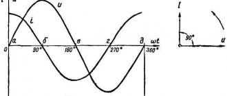
A more detailed examination of this process indicates a zero voltage value in the capacitor at the moment it is turned on. After AC voltage is supplied to it, charging will begin. At this time, the mains voltage will increase during the first quarter of the period. As charges accumulate on the plates, the voltage of the capacitor itself increases. After the mains voltage reaches its maximum at the end of the first quarter of the period, charging stops and the current in the circuit becomes zero.
Device characteristics
The most important characteristic of a storage device is capacity. The charging time depends on it when the device is connected to a power source. The discharge time is directly related to the value of the load resistance: the higher it is, the faster the process of releasing the accumulated energy occurs. This capacity is determined by the following expression:
C = E*Eo*S / d, where E is the relative dielectric constant of the medium (reference value), S is the area of the plates, d is the distance between them.
In addition to capacity, the capacitor is characterized by a number of parameters, such as:
- specific capacitance - determines the ratio of the capacitance to the mass of the dielectric;
- operating voltage - the nominal value that the device can withstand when applied to the plates of the element;
- temperature stability - the range in which the capacitance of the capacitor practically does not change;
- insulation resistance - characterized by the self-discharge of the device and determined by the leakage current;
- equivalent resistance - consists of losses generated at the terminals of the device and the dielectric layer;
- absorption - the process of the emergence of a potential difference on the plates after the device is discharged to zero;
- capacitance - a decrease in conductivity when alternating current is supplied;
- polarity - due to the physical properties of the material used in manufacturing, the capacitor can operate correctly only if a potential with a certain sign is applied to the plates;
- equivalent inductance is a parasitic parameter that appears on the contacts of the device and turns the capacitor into an oscillating circuit.
What's happened
A circuit through which an intermittent current flows has total resistance. It is calculated by the sum of active and reactive resistance squared.
The graphic representation of this formula is a triangle. Its legs are represented by active and reactive resistance, and the hypotenuse is represented by total electrical resistance.
Capacitive electrical resistance (Xc) is one of the types of reactance. This indicator characterizes the resistance of the electrical capacitance in the circuit to electric current with variable parameters. The conversion of electricity into heat does not occur at the moment electricity flows through the container (reactance property). Instead, the energy of the electric current is transferred to the electric field and vice versa. There is no loss of energy during such an exchange.
The capacitance of a capacitor can be compared to a pan filled with liquid; when its volume is completely filled, it turns over, pouring out the contents, and then fills again. After reaching the maximum charge of the capacitor, it is discharged, then it is charged again.
Additional information: A circuit capacitor can only store a limited amount of charge before reversing the voltage polarity. For this reason, intermittent current does not drop to zero, an important difference from direct electricity. Low values of current frequency correspond to low values of charge accumulated by the capacitor, low values of resistance to electricity, which gives reactive properties.
Application in practice
The properties of a capacitor are used in the design of various filters. The effect of capacitance in this case depends on the method of connecting the part:
- If it is connected in parallel with the load, you will get a filter that blocks high frequencies. As they increase, the resistance of the capacitor decreases. Accordingly, the load at high frequencies is shunted more than at low frequencies.
- If the part is connected in series with the load, you will get a filter that delays low frequencies. This circuit also does not allow DC voltage to pass through.
- Another area of application is separating the variable component from the constant one. For example, in the final stages of audio amplifiers. The higher the capacitance, the lower the frequency the connected speaker can reproduce.
In power supply filters, along with capacitance, the property of accumulating and releasing charge is also used. When the load increases, the charged filter capacity is discharged, releasing additional energy. It also suppresses ripple and other parasitic signals by passing them through itself and connecting them to a common wire. Thus, smoothing and maintaining the load voltage within specified limits is ensured, and unwanted inter-stage connections that cause unstable operation are eliminated.
Capacitor resistance measurement.
What determines the resistance of capacitors in AC circuits?
Its indicators depend not only on the capacitive characteristics of the latter, but also on the frequency characteristics of the electric current flowing through the circuit. When we talk about the resistance of a resistor, we are talking about the parameters of the resistor itself, for example, material, shape, but there is absolutely no relationship between its resistance and the frequency indicators of the circuit electricity (we are talking about an ideal resistor, the parasitic parameters of which are not typical). When it comes to a device for storing energy and charging an electric field, everything is different. A capacitor of the same capacitance at different current frequencies has different levels of resistance. The amplitude of the electricity flowing through it at a constant voltage amplitude has a different value.
Considering this formula for the resistance of a capacitor in an alternating current circuit, what conclusions can be drawn? As the signal frequency increases, the electrical resistance of the capacitor decreases.
As the capacitive characteristics of the device for accumulating charge and energy of the electric field Xc of alternating electricity passing through it increase, it will tend downward.
The moment the frequency values approach zero marks on the axis (when the alternating electric current becomes similar in its parameters to constant), is accompanied by an increase in Xc of the capacitor to unlimited values. This is true: it is known that a DC mains capacitor is actually an open circuit. The actual electrical resistance, of course, is not infinite; it is limited by the level of capacitor leakage. But its values remain at a high level, which cannot be ignored.
As the frequency digits increase to the level of infinite values, the capacitance of the electric capacitor tends to zero. This characterizes ideal models. In real conditions, a capacitor has unpleasant characteristics (such as inductance and leakage resistances), so the capacitance decreases up to certain values, after which it increases.
Note! When a capacitor is connected to an electrical circuit with variable parameters, its power is not wasted, because the phase characteristics of voltage and current are shifted by 90° in relation to each other. In one quarter of the period, the electric capacitor is charged (energy is stored in its electric field), the next time it is discharged, the energy goes back into the circuit. Its electrical resistivity is watt-free and reactive.
Formula for the capacitance of a cylindrical capacitor
Now let's talk about how to find the capacitance of a cylindrical capacitor. These include capacitors consisting of two metal cylinders inserted into one another. A dielectric is placed between them to separate them. The formula for the capacitance of a capacitor is as follows:
Here we see several new variables:
- l – height of the cylinder;
- R1 and R2 – radius of the first and second (outer) cylinders;
- ln is not a variable, but a mathematical symbol for the natural logarithm. Some calculators have it.
You should always remember that all quantities must be converted to a single system; the table below shows the international systems of units (SI).
It shows that all distances must be reduced to a meter.
It is also worth paying attention to the quality of the dielectric. If the thickness of the dielectric affects only the capacitance of the capacitor, then its quality affects energy conservation. In other words, a capacitor with a high-quality dielectric will have less self-discharge.
Quality can be determined by the number next to the substance; the larger it is, the better the quality. The comparison is made using vacuum, the value of which is equal to unity.
How to calculate Xc
The current strength of a circuit with constant voltage readings at the time of operation of the electric capacitor is equal to 0. Its value in a circuit with alternating voltage after connecting the capacitor I? 0. As a result, the capacitor imparts less Xc to a chain with a variable voltage than to a chain with a constant voltage.
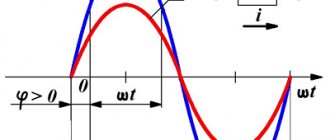
It turns out that voltage changes differ in phase from current changes by π/2.
According to the law formulated by Ohm, the strength of the electric current is directly proportional to the magnitude of the circuit voltage. Formula for calculating the largest values of voltage and current:
f is an indicator of the frequency of intermittent current, measured in hertz;
ω is an indicator of the angular frequency of the current;
C is the size of the capacitor in farads.
Important! Xc is not a parameter of the conductor; it depends on such characteristics of the electrical circuit as the frequency of the electric current.
Increasing the values of this value causes an increase in the transmitting capacity of the capacitor (the limit of its resistance to intermittent current decreases).
Let's imagine that a capacitor with a capacity of 1 μF is connected to the circuit. It is necessary to calculate the level of capacitance at a frequency of 50 Hz and how the capacitance of the AC circuit changes at a frequency of 1 kHz. The voltage amplitude applied to the capacitor is 50 V.
Capacitor charge formula
To perform charging, the capacitor must be connected to a DC circuit. A generator can be used for this purpose. Every generator has internal resistance. When the circuit is closed, the capacitor is charged. A voltage appears between its plates equal to the electromotive force of the generator: Uc = E.
The plate connected to the positive pole of the generator is charged positively (+q), and the other plate receives an equal charge with a negative value (-q). The amount of charge q is directly proportional to the capacitance of the capacitor C and the voltage on the plates Uc. This dependence is expressed by the formula: q = C x Uc.
During the charging process, one of the capacitor plates gains and the other loses a certain number of electrons. They are transferred through an external circuit under the influence of the electromotive force of the generator. This movement is an electric current, also known as charging capacitive current (Icharge).
The charging current flows in the circuit in almost thousandths of a second, until the moment the capacitor voltage becomes equal to the electromotive force of the generator. The voltage increases smoothly and then gradually slows down. Further, the capacitor voltage value will be constant. During charging, a charging current flows through the circuit. At the very beginning, it reaches its maximum value, since the capacitor voltage has a zero value. According to Ohm's law, Izar = E/Ri, since the entire emf of the generator is applied to the resistance Ri.
How is capacitive electrical resistance measured?
R is represented by the ratio of voltage to current in a closed electrical circuit, according to Ohm's law. Units of measurement are Ohms. Xc, as its variant, is also measured in Ohms.
Capacitors are used in the manufacture of filters. When connected in parallel to a circuit, it is capable of delaying high frequencies, and when connected in series, it removes low frequencies. They are also used to cut off the variable part from the constant part. It is indispensable in radio engineering, in the production of proximity sensors, and for monitoring production processes. Technologies with the properties described above are used in all areas of industry.
In alternating current circuits the following types of resistance are distinguished.
Active . The resistance of a resistor is called active. Symbol
The unit of resistance is Ohm. The resistance of the resistor does not depend on frequency.
Reactive . In the reactive section, three types of resistance are distinguished: inductive xL and capacitive xc and reactive itself. For the inductive reactance, the formula XL = ωL was obtained above. The unit of inductive reactance is also Ohm. The xL value depends linearly on frequency.
For the capacitance above, the formula XC = 1 / ωC was obtained. The unit of capacitance is Ohm. The value of xc depends on the frequency according to an inversely proportional law. Simply the reactance of a circuit is called the value X = XL - XC.
Total resistance . The total resistance of a circuit is called the quantity
.
From this relationship it follows that the resistances Z, R and X form a triangle: Z is the hypotenuse, R and X are the legs. For convenience, in this triangle we consider the angle φ, which is determined by the equation
and is called the phase shift angle. Taking this into account, additional connections can be made
Analysis of linear electrical circuits (page 3)
A comparison of the reactive (1.22) and complex (1.31) inductance resistance shows that on the complex plane the reactive (inductive) resistance of the coil is laid on the positive vertical semi-axis (Fig. 1.32, b
), because this quantity is imaginary and positive.
Let us write down the expressions for the complex amplitudes of current and voltage for a circuit containing a capacitance. From (1.16) and (1.26) it follows that:
,
where U mC
and
I m
, as well as j
u
and j
i
are related by relations (1.27).
The voltage vectors on the capacitor and the current in it are shifted relative to each other by –90°, while the current leads the voltage (Fig. 1.31, c
).
We find the complex resistance of the capacitance as:
It is taken into account here that .
Obviously, the reactance of the capacitance is an imaginary negative number; on the complex plane it is plotted on the negative vertical semi-axis (Fig. 1.32, c
).
We already know that any complex number written in algebraic form has a real a
and imaginary
jb
components, and the number written in exponential form is the module
A
and the argument j.
Analysis of expressions (1 shows that the complex resistance of the resistor is real and does not contain an imaginary component, its argument is zero; the complex resistance of inductance, on the contrary, is imaginary, its argument is +90°; the complex resistance of the capacitance is also imaginary, but its argument is –90 °.
In Fig.
1.33, a
and 1.34,
a
show sequential
RL
and
RC
circuits.
The complex resistance of a series RL
circuit in algebraic form contains the sum of a positive real resistive resistance
R
and a positive imaginary inductive resistance
j X L
(Fig. 1.33,
b
):
Where .
In exponential form, this resistance will be written as:
,
where modulus Z RL
is called
the total resistance
of the series
RL
circuit, and the argument j
Z
is
the angle
of this resistance.
The impedance Z RL
and the argument j
Z
are calculated as follows from Fig.
1.33, b
, according to formulas
Example 1.11.
Let us determine the complex resistance of the circuit shown in Fig.
1.33, a
, at a frequency of 50 Hz for
R
= 10 Ohm and
L
= 100 mH.
Let's calculate the value of the inductive reactance of the circuit using (1.31),
Complex resistance RL
-chains
Impedance
Drag Angle
In exponential form, the complex resistance RL
-chains
Complex resistance of series RC
the circuit in algebraic form consists of a positive real resistive resistance
R
and a negative imaginary capacitive resistance (Fig. 1.34,
b
):
Where
In exponential form, this complex number looks like
,
where is the total resistance of the series RC
chains;
is the angle of this resistance.
Complex impedance Z RC
shown in Fig.
1.34, b
in the form of a vector on the complex plane. Its projections onto the real and imaginary axes are also shown there.
A right triangle made up of resistive, reactive and impedance (Fig. 1.35) is called
resistance
triangle .
Example 1.12.
Let us determine the complex resistance of the circuit shown in Fig.
1.34, a
, at a frequency of 5 kHz for
R
= 100 Ohm,
C
= 318 nF.
Let's calculate the value of the capacitance of the circuit
Complex resistance RC
-chains
RC complex resistance vector
-chain is shown in Fig. 1.36.
Let's write down the complex resistance of the serial RLC
chains (Fig. 1.37,
a
).
It will contain a positive real resistive resistance R
and an imaginary resistance, the sign of which will depend on the ratio of inductive
XL
and capacitive
resistance XC
,
Where .
Recall that the values of XL
and
XC
depend on frequency and on the corresponding elements
L
and
C
, so it may happen that at a certain frequency and for certain values of
L
and
C
the value of
XL
will be greater than the value of
XC
, as shown in Fig.
1.37, b
, or vice versa, the value of
XC
will be greater than
XL
(Fig. 1.37,
c
).
From the resistance triangle it is easy to calculate resistive and reactance, knowing the total resistance and its angle:
.
The case when reactance X =
0, i.e.
XL
=
XC
, is special.
When this occurs, the series RLC
circuit is said to have
voltage resonance
.
The frequency at which inductive and capacitive reactances are equal is called voltage
resonance frequency .
The complex resistance of the entire RLC
is equal to the resistive resistance
R. In the future, the phenomenon of voltage resonance will be considered in more detail.
Example 1.13.
Let us determine the resistive and reactance of a series
RLC
circuit whose complex resistance
Resistance
Reactance
Resistance X
=
X L
–
X C
is positive, i.e.
X L
>
X C
, the resistance triangle of such a circuit is shown in Fig. 1.38.
When connecting elements in parallel, it is more convenient to deal not with resistances, but with conductivities - resistive G =
1/
R
, reactive and, complete
Y =
1/
Z
and complex
Y =
1 /
Z. If, when connecting elements in series, we add
If their complex resistances were calculated, then when connected in parallel, their conductivities are added up.
For parallel RLC
circuit (Fig. 1.39,
a
) its complex conductivity will be written in the form:
,
where G =
1/
R
– resistive conductivity;
– capacitive conductivity;
– inductive conductivity;
– reactive conductivity;
– total conductivity;
– conductivity angle.
Resistive and reactive conductivity can be found from the conductivity triangle (Fig. 1.39, b
):
.
The case where reactivity B
equals zero, that is, when it is also of particular interest.
At this moment,
current resonance
occurs RLC .
Therefore, the frequency at which the reactive conductivities of the branches coincide is called the current resonance frequency
.
The complex conductivity of the entire circuit at resonance becomes equal to the resistive
conductivity G. The phenomenon of current resonance will be discussed in more detail later.
Example 1.14.
Determine the complex resistance of a parallel
RLC
circuit (Fig. 1.39,
a
) at a frequency
f
= 1 kHz for
R
= 100 Ohm,
L
= 10 mH,
C
= 10 μF.
The circuit elements are connected in parallel, so let’s first calculate the complex conductivity Y RLC
, using expression (1.36).
Resistive conductivity
Inductive conduction
Capacitive conductivity
Complex conductivity of the circuit
The complex resistance of a circuit is inversely proportional to the complex conductance, therefore
From this section we learned that:
1.3. Calculation of chain reactions in symbolic form
Calculation of reactions in a circuit with one source
. The following calculation procedure is used:
1. A circuit containing a source of harmonic oscillations is transformed by replacing its elements with their complex resistances, and the instantaneous values of emf, currents and voltages are recorded in complex (symbolic) form.
2. Calculate the complex values of currents in the branches and voltages on the resistances using Ohm’s law and Kirchhoff’s laws.
3. Determine the corresponding instantaneous values of currents and voltages in the circuit.
Example 1.15.
Let us determine the instantaneous values of current and voltage on the elements of a circuit containing a harmonic voltage source B, resistance
R
= 300 Ohm, inductance
L
= 0.6 H and capacitance
C
= 0.625 μF (Fig. 1.40).
In accordance with the procedure for calculating the reaction in a circuit with one source, we replace the circuit elements with their complex resistances.
Analyzing the expression for the instantaneous voltage value u
(
t
), we determine that the circular frequency w = 2000 rad/s, i.e., the oscillation frequency
f
= w/(2p) = 318.3 Hz.
Resistance R
= 300 Ohm remains unchanged.
Inductance L
= 0.6 H is replaced by resistance
Capacity C
= 0.625 µF replaced by resistance
Let us represent the harmonic voltage in exponential form as
Current i
(
t
) is replaced by the complex current
I m
, and the voltages
u R
(
t
),
u L
(
t
) and
u C
(
t
) are replaced by the complex voltages
U m R
,
U m L
and
U mC
, respectively.
As a result, we obtain the diagram shown in Fig. 1.41.
To determine the current and voltage in this circuit, we first calculate the complex resistance of the circuit Z
relative to the source terminals. All resistances are connected in series, so
Note that the inductive and capacitive reactances of the circuit partially compensated each other and that the reactance of the circuit is less in magnitude than the resistance of any of the reactive elements.
In fact, it is possible to completely eliminate the presence of reactance in the circuit by changing the frequency of the voltage generator until the condition | Z L
|
= | Z C
|.
In the example under consideration, the resistance of the circuit is inductive in nature, since the reactive component of the complex resistance of the circuit has a plus sign.
Complex current I m
in the circuit we will determine using Ohm's law for the complex voltage
U m
of the source
Z.
We have:
Converting complex impedance Z
into exponential form to simplify the division of complex numbers, we get
The amplitude value of the current is 0.02 A, and the initial phase is –53°.
The voltage across the circuit resistances is determined by multiplying the current I m
to the corresponding resistances.
Current Im _
has an initial phase (–53°), voltage
U m R
has the same initial phase, i.e. vectors
I m
and
U m R
are directed along the same straight line in the vector diagram shown in Fig. 1.42.
The voltage across the inductance leads the current by 90°, so U m L
is ahead of the vector on the horizontal axis of Fig. 1.42 at 37°.
The voltage across the capacitance lags behind the current by 90°, and from the horizontal axis by 143°.
Note also that the phase shift between U m L
and
U mС
is 180°.
In accordance with Kirchhoff's stress law
The last two terms represent the sum of the voltages across the inductance and capacitance, and this total vector can be directed either along U m L
, or by
U mС
depending on which of these voltages is greater in magnitude.
In our case, it has the direction U m L
.
Vector U m R
can be added to the sum
U m L
+
U m C
and the result is the vector
U m
, as shown in Fig. 1.42.
Instantaneous values of current and voltage on the circuit elements can be written in the form
A phasor diagram is often useful in explaining and interpreting calculation results.
Example 1.16.
Let's find the currents and voltages in the circuit shown in Fig.
1.43, if the given values are R
1 = 2 Ohm,
R
2 = 2 Ohm, X
L
= 4 Ohm, X
C
= 2 Ohm, .
First, let’s determine the complex resistance Z
ab of the parallel connection of resistor
R
2 and capacitance X
C
:
Resistance Z
ab can be represented as
Z
ab = =
R
ab –
j X
ab.
We obtain the equivalent circuit shown in Fig. 1.44.
The equivalent complex resistance of the circuit is defined as
Current (Fig. 1.45) is determined by Ohm's law:
Currents I m
1 and
I m
2 are determined using the scatter formulas:
It should be noted that according to Kirchhoff’s current law, I m
1 +
I m
2 =
I m
. The vector diagram of currents is shown in Fig. 1.46.
Let's determine the voltages on the circuit elements (Fig. 1.43):
According to Kirchhoff's stress law (Fig. 1.47)
Calculation of reactions in a circuit with several sources.
All methods for calculating circuits in direct current mode are also applicable to calculating circuits under harmonic influence. Superposition, nodal voltage, loop current, and equivalent generator methods are used to determine reactions in a circuit with multiple sources of harmonic oscillations.
The calculation is performed for a symbolic form of recording currents, voltages and circuit resistances.
Example 1.17.
Using the superposition method, we determine the currents in the branches of the circuit shown in Fig.
1.48, if the given values are R
1 = 2 Ohm,
X L
= 4 Ohm,
X C
= 2 Ohm,
Let us select the directions of currents in the branches of the circuit (Fig. 1.48). Since there are two sources in the circuit, the true directions of the currents are unknown, so we choose them arbitrarily.
The superposition method is based on the principle of superposition, according to which the reaction of a linear chain to the sum of impacts is equal to the algebraic sum of the reactions from each impact separately.
Partial circuits, in each of which only one source is left, and the other is replaced by its internal resistance, are shown in Fig. 1.49, a
and 1.49,
b
.
Let's calculate the currents in the first partial circuit (Fig. 1.49, a
). The internal resistance of the current source is equal to infinity, therefore . According to Ohm's law
Let's consider the second partial scheme (Fig. 1.49, b
). The current is equal to the current of the current source, i.e.
We calculate the currents using the scatter formula,
Currents in the branches of the original circuit
Example 1.18.
Using the nodal voltage method, we determine the currents in the branches of the circuit shown in Fig. 1.48.
We ground node 2. The potential of this node is zero, V m
2 = 0.
For node 1 we compose the equation of state:
In this equation Y
11 is the own conductivity of node 1, i.e. the sum of the conductivities of all branches connected to node 1:
Y
12 – mutual conductivity of nodes 1 and 2, coinciding in the example under consideration with the value
Y
11;
I m
у1 – nodal current of node 1:
From the equation of state we find the potential of the first node
We find the currents in the branches according to Ohm's law:
Values of currents in the branches of the circuit Fig. 1.48 are the same as when calculating by the superposition method.
Example 1.19.
Using the loop current method, we determine the currents in the branches of the circuit shown in Fig. 1.48.
Let us select the directions for bypassing the circuits in the circuit (Fig. 1.50).
Loop current
To determine the loop current, we create an equation of state:
In this equation Z
11 – own resistance of circuit 1, equal to the sum of the resistances of all branches forming this circuit:
Z
12 – mutual resistance of circuits 1 and 2:
U m
k1 – loop voltage:
From the equation of state we find the loop current I m
k1:
Knowing the loop currents, we find the branch currents,
The current values coincide with those obtained when calculating the circuit using the superposition and nodal voltage methods.
Example 1.20.
Using the equivalent generator method, we determine the current
I m
1 in the circuit shown in Fig. 1.48.
Let's open the branch with the capacitance and to determine the open circuit voltage U m
xx let's create an equation using Kirchhoff's second law
In idle mode, current I m
xx = –
I m
g, therefore
Equivalent generator resistance Z
eg equals
Current Im _
1 will be found using the formula
We get the same value I m
1, as when using other calculation methods.
From this section we learned that
1.4. Complex transmission coefficient
Consider the electrical circuit shown in Fig. 1.51.
We may be interested in any response of the circuit (voltage or current in any element or branch of the circuit) to any of the applied influences. In this case, it is convenient to represent the circuit as a four-terminal network, at the input of which is a source with a given effect, and at the output is the element of interest to us, for example, as is done in Fig. 1.52.
A symbolic representation of voltages and currents at the input and output of a two-terminal network is shown in Fig. 1.53.
The most important characteristic of a linear electrical circuit is the complex transfer coefficient H
. It is determined by the ratio of the complex amplitude of the reaction to the complex amplitude of the effect.
Depending on what is considered a reaction and an impact, the following types of transfer coefficients are distinguished.
1. Complex voltage gain
2. Complex current transfer coefficient
3. Complex transfer resistance
4. Complex transfer conductivity
Complex number H
can be presented in demonstrative form
where N
is the module of the transfer function, and j is its argument.
Indeed, consider the transfer function
.
Transfer function module
represents the ratio of the amplitude of the harmonic response of the circuit to the amplitude of the harmonic influence, i.e. it shows how many times the amplitude of the harmonic oscillation at the input of the circuit changed as the oscillation passed through the circuit. Therefore, the value of H u
called
voltage transfer coefficient
.
Transfer function argument
shows the change in the initial phase of the input oscillation after the transmission of this oscillation through the circuit and is called the phase shift
.
Knowing the complex transmission coefficient of a circuit allows one to calculate the response of the circuit to a harmonic influence. The amplitude of the reaction is
and its initial phase
In other words, to find the amplitude of the harmonic oscillation at the output of the circuit, you need to multiply the amplitude of the input harmonic oscillation by the voltage transfer coefficient, and to find the initial phase of the output harmonic oscillation, you need to add the phase shift introduced by the circuit to the initial phase of the input harmonic oscillation.
In symbolic notation form, the complex amplitude of the harmonic oscillation at the output of the circuit is determined from the relation:
The current transfer coefficient is calculated in the same way
and phase shift of current oscillation
total transfer resistance of the circuit
and the phase angle of this resistance
as well as total transmission conductivity
and its phase angle
In general terms we can write
It is obvious that in the diagram of Fig. 1.51 the reaction can be voltage or current in any element or any branch of the circuit, and not only voltages or currents of sources, but also any voltages or currents of elements (branches) of the circuit can be used as an influence.
Example 1.21.
Let's find the complex voltage transfer coefficient of the circuit given in Example 1.15 if the reaction of the circuit is the voltage across the capacitance
u C
(
t
).
When solving Example 1.15, the impact was written in symbolic form
The voltage across the capacitance, i.e. the reaction of the circuit, was also determined:
Complex transmission coefficient
Voltage gain
shows that when passing through the circuit, the amplitude of the impact decreased by 10 times.
Phase shift
shows that the capacitance voltage lags the input oscillation by 143°.
Example 1.22.
Let us find the complex current transfer coefficient of the circuit shown in Fig.
1.54, if I m
g = 5
e j
90°, A,
R
2 = 10 Ohm,
L
= 30 mH,
f
= 50 Hz, the reaction of the circuit is the current in the inductance.
To calculate the complex current transfer coefficient,
it is necessary to determine the current in the inductance. Using the scatter formula, we get:
Complex current transfer coefficient
It is obvious that the complex transmission coefficient of the circuit is determined by the values of the circuit elements R
2,
L
and frequencies
f
.
Example 1.23.
Let's find the voltage across the inductance
u L
(
t
) in the circuit shown in Example 1.22 if the complex transfer resistance
H Z
= 6.86
e j
46.8° Ohm.
Voltage amplitude across inductance
Initial phase of voltage across inductance
Instantaneous voltage value
From this section we learned that
Questions and tasks for self-control
1. What oscillations are called harmonic?
2. What parameters characterize harmonic oscillation?
3. How is the magnitude and sign of the initial phase of a harmonic oscillation determined from its graph?
4. How are the frequency and period of a harmonic oscillation related?
5. Write down an expression for the instantaneous current value, the graph of which is shown in Fig. 1.5, b
, if the oscillation period is
T
= 2 s.
Determine the current value at time t
1 =
T
/8.
6. Construct stress graphs u
1(
t
) = ,
u
2(
t
) = .
7. What is the connection between the vector and time representation of harmonic oscillations?
8. Construct the vectors of harmonic oscillations given in paragraph 6.
9. Construct graphs of harmonic oscillations in one coordinate system, which correspond to the vectors and rotating with the same frequency. Determine the phase shift of these oscillations.
10. What is the relationship between the parameters of the complex and time representation of harmonic oscillations?
11. Formulate Ohm’s law for resistive, inductive and capacitive circuits.
12. What is the phase shift between voltage and current in a resistor (capacitance, inductance)?
13. How is the complex resistance of a series connection R
,
L
,
C
elements?
14. How is the complex conductivity of a parallel connection R
,
L
,
C
elements?
15. Determine the complex resistance of the circuit shown in Fig. 1.55 if
R
1 = 20 Ohm,
R
2 = 40 Ohm,
X L
= 30 Ohm,
X C
= 40 Ohm.
Construct a circuit resistance triangle.
16. What methods are used to calculate circuits with sources of harmonic oscillations?
17. Calculate the currents in the branches of the circuit shown in Fig. 1.55, if voltage is applied to the input, V. Construct a vector diagram of the currents.
18. Calculate current I m
2 in the circuit shown in Fig.
1.56, by the superposition method and the equivalent generator method, if the given resistances are R
= 10 Ohm,
X L
= 30 Ohm,
X C
= 20 Ohm and
U m
= 10
ej
0° V,
I m
g =
ej
270° A.
19. What is complex transmission coefficient? What types of complex transfer coefficients are known?
20. Determine the transfer coefficients in the circuit of Example 1.16 if the reaction is I m
2.
* A distinction should be made between resistors, inductors and capacitors as physical elements of an electrical circuit and resistive, inductive and capacitive elements as idealized elements that have the properties of irreversible energy dissipation or the properties of energy storage of magnetic and electric fields. In engineering practice, resistive, inductive and capacitive elements are often called simply resistance, inductance and capacitance, essentially identifying the element with its parameter. In the future, for simplicity, where this will not lead to misunderstanding, we will also use this terminology.
| Due to the large volume, this material is placed on several pages: 3 |
Get text
Element r (resistor)
Let's set the voltage and current in the form of ratios
It is known that for a resistor ψu = ψi, then for p we get
From equation (2.32) it is clear that the instantaneous power is always greater than zero and varies over time. In such cases, consider the average power over the period T
.
If we write Um and Im through the effective values of U and I: ,, then we get
The form of equation (2.34) coincides with direct current power. The value P equal to the product of the effective values of current and voltage is called active power. Its unit of measurement is Watt (W).
Methods of connecting elements
Mounting the product on the board can be vertical or horizontal. When using several products, they can be connected to each other in different ways.
Parallel connection
To organize it, you need to connect a group of parts to an electrical circuit so that the plates of all parts are connected directly to the switching points. Since all components receive charge from the same current source, they will have the same potential difference. But since the charge accumulates on each product separately, the amount of electricity on the group can be expressed as the sum of the quantities on its parts.
This is also true for capacitive data - the value for the configuration is equal to the sum of the values of each unit. Therefore, such a group can be considered equal to one capacitor, the capacitive parameter of which is equal to the sum of those for all parts.
Serial connection
This scheme involves connecting devices one after another, when only the two outermost products are connected to the connection points in the circuit. The amount of electricity for each part will be the same. In this case, the less capacitive the device, the higher the voltage value will be observed on it.
Important! The capacitance value of such a system will be even less than that of a device with the lowest value. The relationship looks like this: 1/C = 1/C1 + 1/C2 + 1/C3 + ... Based on it, we can directly derive formula C. For two elements: C = C1*C2 / C1+C2.
Serial connection
Mixed compound
Such a complex structure contains fragments with the above two types of connections. To calculate the total capacity, the circuit is divided into simple blocks, consisting only of parts connected in one way. Find equivalent values for each block and then draw the diagram again in a simplified form. Calculate data for the resulting system.
To be able to select a suitable capacitor set, you need to be able to find out the capacitance data. It is also important to know how the indicator is calculated for a configuration of several parts connected to each other in one way or another.
Element l (inductance)
It is known that in inductance the phase relationship is ψu = ψi + 90°. For instantaneous power it has
.
Averaging equation (2.35) over time over the period T, we obtain
.
To quantify the power in the inductance, use the QL value equal to the maximum value pL
and call it reactive (inductive) power. The unit of measurement chosen was VAR (volt-ampere reactive). Equation (2.36) can be written in terms of the effective values of U and I and using the formula UL = I XL we obtain
Practical measurements
The capacitance value of the capacitor is indicated on the case in fractional farads or using a color code. But over time, components can lose their qualities, so for some critical cases the consequences may be unacceptable. There are other circumstances that require measurements. For example, the need to know the total capacity of a circuit or piece of electrical equipment. There are no devices that directly read the capacitance, but the value can be calculated manually or by processors integrated into the measuring devices.
To detect the actual capacitance, an oscilloscope is often used as a means of measuring the time constant (t). This value indicates the time in seconds during which the capacitor is charged by 63%, and is equal to the product of the circuit resistance in ohms and the circuit capacitance in farads: t = RC. An oscilloscope makes it easy to determine the time constant and makes it possible to use calculations to find the required capacitance.
There are also many models of amateur and professional electronic measuring equipment equipped with functions for testing capacitors. Many digital multimeters have the ability to determine capacitance. These devices are capable of charging and discharging a capacitor in a controlled manner with a known current and, by analyzing the increase in the resulting voltage, produce a fairly accurate result. The only drawback of most of these devices is the relatively narrow range of measured values.
More complex and specialized tools are bridge meters, which test capacitors in a bridge circuit. This indirect measurement method provides high accuracy. Modern devices of this type are equipped with digital displays and the ability to be used automatically in a production environment, they can be interfaced with computers and export readings for external monitoring.