4.6
Average rating: 4.6
Total ratings received: 74.
4.6
Average rating: 4.6
Total ratings received: 74.
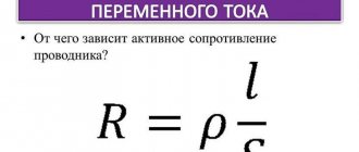
Conductor resistance limits the amount of current in an electrical circuit. The higher the resistance, the lower the current. The conductor resistance can be calculated in two ways: the first method is to use the Ohm's law formula, and the second calculation option involves knowing the geometric dimensions of the conductor and the resistivity of the substance from which it is made.
Why does the conductor “resist”?
The voltage U applied to the ends of the conductor creates an electric field inside it, which sets in motion the free electrons of the substance. Electrons, having received additional kinetic energy, begin to move in an orderly manner in one direction, thereby creating an electric current in the circuit.
As they move, electrons collide with neutral and charged atoms that make up the conductor and lose energy. The mass of an atom exceeds the mass of an electron by thousands of times, so their collision leads to a change in the direction of electron motion and a loss of speed (“braking”).
This creates resistance to the flow (increase) of current.
Rice. 1. Electric current in a conductor is limited by the collision of electrons with atoms.
Introduction
Warning systems are widely used in various fields of human activity, for example, warning and evacuation control systems, emergency warning systems (local LSO and centralized central warning systems). The main purpose of the warning system is to notify people about a particular threat, to convey to them information concerning their personal safety in the event of any emergency situations: fires, man-made disasters, terrorist threats. Warning systems are a mandatory component of almost any security system, in which they are the final executive element - an intermediary between technical means and people. The reliability of information transmission in the warning system is confirmed by electroacoustic calculations, part of which is the calculation of the optimal cross-section of the conductor of the wire, minimizing losses
.
Alarm systems, depending on the conditions of use and the method of transmission, can be divided into wireless and wired. Wired systems that transmit sound or speech information are called broadcast systems.
Broadcasting systems, depending on the principle of construction, can be divided into local and distributed. Distributed audio broadcast systems use the principle of transformer matching, in which specialized transformer loudspeakers are connected to broadcast amplifiers - amplifiers with a transformer output stage. When building distributed systems, loudspeakers, which are the load, are connected to the connecting line in parallel and distributed along it. With transformer matching, sound information is transmitted at increased voltage, which reduces currents and, consequently, the load on the wires, increases the length of the connecting line and the signal transmission range. Extended transmission lines are built as follows: first, the main line is laid, to which the load is connected through distribution boxes.
In transmission lines, losses inevitably occur due to the presence of the conductor's own resistance. Large losses can lead to a decrease in the level and quality of the transmitted signal, so the task of calculating losses on wires and the associated task of calculating the optimal cross-section of the conductor of a connecting line wire is not unimportant.
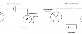
Calculating resistance using Ohm's law
The German physicist Georg Ohm discovered in 1826 that the ratio of the voltage U between the ends of a metal conductor, which is part of an electrical circuit, to the current strength I is a constant value:
$ R={U \over I}=const $ (1),
Where:
U—voltage, V;
I—current strength, A;
R - resistance, Ohm.
This quantity came to be called electrical resistance. Using this formula, you can experimentally determine the value of the unknown resistance.
Rice. 2. Circuit for measuring voltage and current to determine the resistance of a circuit section.
To do this, an ammeter measures the amount of electric current through a resistance, and a voltmeter measures the voltage in a section of the circuit. Next, using formula (1), the value of R is calculated.
The unit of measurement is named after Georg Ohm. An electrical resistance of 1 Ohm has a section of the circuit where, at a current of 1 A, the voltage is 1 V:
$$ 1 Ohm = { 1 V\over 1 A} $$
How to measure the ohmic resistance of cable insulation
Before testing, remove residual charge from disconnected live parts. This is done by connecting them to the ground bus. The contact jumper is removed only after connecting the measuring device. At the end of the test, the residual charge is removed again by briefly shorting it to ground. You can find the resistance value in two ways: either using a calculation or a table, or directly using instruments.
According to the PUE table
Resistance values depend on the cross-section of the element conducting the electric current and the material from which it is made.
Aluminum wire table
This is usually copper or aluminum. The main values are shown in the table:
Table for copper wire
Using instruments
Typically, the equipment used to make measurements is divided into two groups: panel meters and meggers. The first is used for mobile or stationary electrical installations with an independent neutral. Indicators and relay components are included in a typical insulation monitoring equipment design. These meters can operate in continuous mode and can be used in 220 V or 380 V AC networks with different frequencies.
In most cases, the measurement is made using a megger. It differs from conventional ohmmeters in that it can operate at fairly high voltage values generated by the device itself. There are two types of megohmmeters:
- Analog.
Analog device
- Digital.
Digital sensor A standard megger contains three sensors. The following are connected to them: protective grounding, test leads, shielding. The latter is used to eliminate leakage current.
The measurement method can be expressed as follows:
- The test voltage is selected according to the requirements of the production line. For example, for home wiring, the value is set in the range from 100 to 500 V.
- When using a digital device, you must press the “Test” button, and on an analog device, turn the knob until the indicator shows the required voltage value.
- Connect the linear output of the tester to the test core of the cable, and the grounding output to the harness of the remaining wires. That is, each core is checked in relation to the remaining electrical wires electrically connected to each other.
Important! If the received data is unsatisfactory, each core in the cable is checked separately.
- Record all obtained values and compare them with specifications.
Connecting the sensor to cables
Calculation using resistivity
Conductor resistance can be calculated without measuring voltage and current values. But for this you need to know additional information about the conductor.
Rice. 3. A conductor with cross-section S and length L through which current I flows.
Georg Ohm and other researchers experimentally determined that the resistance of a conductor is directly proportional to the length of the conductor L and inversely proportional to the cross-sectional area of the conductor S. This pattern can be described by the formula for calculating the resistance of the conductor:
$ R = ρ *{ L\over S} $ (2)
The coefficient ρ was called resistivity. This physical quantity reflects the characteristics of a particular substance, which depend on the density of the substance, crystal structure, atomic structure and other internal parameters. It is not necessary to calculate the resistivity of the conductor every time, since for most substances the resistivities are measured and summarized in reference tables, which can be found in paper reference books or in their online versions.
But if such a need arises, then from formula (2) you can obtain the following formula (3), and use it to calculate ρ:
$ ρ = R*{ S\over L } $ (3)
Silver has one of the lowest ρ values, equal to $0.016{Ohm*mm^2\over m}$. This explains the use of such a rather expensive metal for soldering especially important radio components (microcircuits, microprocessors, electronic boards), which should heat up as little as possible during operation.
Are calculations required?
As we have already said, the cross-section of the wire is selected based on the expected current and the resistance of the metal from which the wires are made. The logic of the choice is as follows: the cross-section is selected in such a way that the resistance at a given length does not lead to significant voltage drops. In order not to carry out a series of calculations, for short lines (up to 10-20 meters) there are fairly accurate tables:
This table shows the typical cross-sectional values of copper and aluminum conductors and the rated currents through them. For convenience, the load power that this line will withstand is indicated. Please note the difference in currents and power at a voltage of 380V; naturally, this assumes a three-phase power supply.
Finally, we recommend watching a video that explains in detail how to calculate the cross-section of a conductor, and also provides examples of calculation work:
Calculating wire resistance comes down to using a couple of formulas, and you can download ready-made calculators from the Play Market for your smartphone, for example, “Electrodroid” or “Mobile Electrician”. This knowledge will be useful for calculating heating devices, cable lines, fuses, and even today’s popular coils for electronic cigarettes.
Calculation of the cross-section of the wire core taking into account losses in the line
Let's return to calculating the cross-section of the wire core. Let's calculate the cross-section of the wire core of a distributed line, taking into account voltage losses. Let us remember that formula (9) is based on the assumption that voltage losses in the line should not exceed 10%, which made it possible to use the ratio: Rl / Rn = 0.1. If the loss value is different from 10%, this ratio will change. Let's construct a coefficient that allows us to take into account any expected losses in the line, as Kp = Rн / Rл.
This coefficient can be conveniently associated with voltage losses and interpreted as expected losses. Using formula (15) we obtain:
Let's check the validity of this formula: When Pn “tends to” 100%, Kp “tends to” 0, Rн “tends to” 0 - all the voltage remains on the line. When Pn “tends to” 50%, Kp “tends to” 1, Rl=Rn – the voltage on the line and the load is the same. When Pn “tends to” 10%, Kp “tends to” 9, Rl = 0.11 Rn - the voltage on the line is approximately 10 times less than at the load. When Pn “tends to” 0%, Kp “tends to” ∞, Rl tends to 0 - the voltage on the line tends to 0.
Let us supplement formula (14) with this coefficient:
Calculation example
Let's calculate the sound pressure of the loudspeaker, taking into account losses on the wires.
Loudspeaker sound pressure: Pdb=SPL+10 lg (Pgr), where: SPL – loudspeaker sensitivity, dB, Pgr – loudspeaker power, W.
It is convenient to enter power losses into this formula (formula 18) and interpret this formula as: Sound pressure level calculated taking into account power losses: Pdb=SPL 10 lg (Pgr (100-Pm)/100), where Pm – power losses, %.
Calculation of the cross-section of the conductor of a wire in a distributed line
In broadcast systems with transformer matching, loudspeakers are connected to a common line, always in parallel and distributed along it with varying degrees of uniformity (see Fig. 3).
Rice. 3 - Equivalent circuit of a distributed line
In a distributed system, transformer loudspeakers (transformer loudspeakers are connected to the main line only in parallel, as a rule, through distribution boxes (the resistance of which we do not take into account) are connected to the main line with cross-section S, through distribution boxes with taps of a smaller cross-section Si. To calculate the cross-section of the core wire of the taps of the distributed line, you can use formula (9): Si = 20rli Pgri / Ul2, where li is the length of the i-th branch - the distance from the main line (distribution box) to the loudspeaker (m), Pgri - the power of the i-th loudspeaker, W.
The most pressing task is to calculate the cross-section of the main core of the wire, the transmission line. In real distributed structures, the distances to the loudspeakers, as well as their power, vary. Such problems are solved by iterative methods using Kirchhoff's laws and require special calculation skills or the use of software.
The simple and effective method proposed below can be used to solve a wide range of problems. The essence of the method is based on an obvious and simple consideration: if most of the load is concentrated not at the end, but at the beginning of the line, then the total load on the wires will decrease.
Example: For the situation shown in Fig. 4, the equivalent load power Peq = P1 + P2 is somewhere in the middle between loudspeakers with powers P1 and P2.
Rice. 4 - An example explaining the meaning of the distribution coefficient
Let us introduce a coefficient that takes into account the unevenness of the load and is based on the already constructed formula (9, valid for the case when the entire load is concentrated at the end of the line), from which it can be seen that the cross-section of the wire core is directly proportional to two variables: the length of the line and the load power and, therefore , the distribution coefficient must be normalized with respect to these variables. Let's give a definition:
Load distribution coefficient Kr
– dimensionless coefficient taking into account the load distribution along the line, Fig. 4:
In distributed lines that use loudspeakers of the same rating Рgr, the total load can be calculated as: Рн = nРgr and in this case the distribution coefficient is represented as the arithmetic average of the distances to the loudspeakers:
In the case where the distances to the loudspeakers Li are not known, the distribution coefficient Kp can be represented as the arithmetic mean between two cases when the entire load is located at the beginning of the line (L = L / n) and at the end of the line (L = Ln):
The dependence of the distribution coefficient Kр (12) on the number of loudspeakers n is given in Table 1 (formula 12 is valid: for one loudspeaker (n = 1), Kр = 1, for a large number n = 10, Kр tends to 0.5).
Table 1
Dependence of the distribution coefficient value on the number of load elements (loudspeakers)
| n | 1 | 2 | 3 | 4 | 5 | 6 | 7 | 8 | 9 | 10 |
| Kr | 1 | 0,75 | 0,67 | 0,63 | 0,6 | 0,58 | 0,57 | 0,56 | 0,56 | 0,55 |
The most common case is when the entire load is distributed in some pre-known interval from L1 to L, where: L is the total length of the line. In this case, the distribution coefficient can be represented as the result of averaging in the range from L1 to L (the arithmetic mean between L1 and (L - L1) (n +1) / 2n (see f-lu, 12), normalized relative to L):
Let's check the validity of formula (13):
as L1 tends to 0, Kр tends to ((n+1))/2n – formula (12);
at L= L1, Kр = 1 – the entire load is concentrated at the end of the line.
Example: Let's calculate the distribution coefficient for the case when the load (for example, 10 loudspeakers) is located in a building located at a distance of L1=300m from the amplifier. Total line length L=500m: Kr=(300+0.55*(500-300))/500=0.82.
It is convenient to present the distribution coefficients for different cases in the form of a table:
table 2
Distribution coefficients Kp for various cases
| Formulas for calculating Kr | Condition of use |
| This formula is used if the powers and distances to the load elements are known. | |
| This formula is used if the powers of the load elements are equal and the distances to the load are known. | |
| This formula is used if the distance to the first loudspeaker and the total length of the line are known, but the power of the load elements is not known. | |
| This formula is used if the power and distances to the load elements are not known. |
Let us introduce the distribution coefficient Kр, Table (2), into formula (9):
Calculation of the cross-section of the wire strand depending on the length and load in the line
There are losses in any communication line. A line - a strand of copper wire - has a certain resistance, depending on the length, and, therefore, according to Kirchhoff's law, the voltage must drop across it and a certain power must be released. In broadcast systems, transformer loudspeakers are used as a load. Impedance of a transformer loudspeaker Z is the resistance of the primary winding of the transformer at a frequency of 1 kHz. The resistance of the load or line is a frequency-dependent (complex) quantity, so in this case an elementary estimation calculation is performed for the geometric mean frequency of the entire frequency range (most manufacturers indicate the impedance of a transformer loudspeaker for a frequency of 1 kHz, which corresponds to the middle of the standard frequency range 0.2 - 5 kHz) .
We will solve the problem of determining the cross-section of a wire core in 2 stages, using the known representation of the line and load, in the form of a resistive divider (see Fig. 2).
Rice. 2 - Equivalent load connection diagram at the end of the line
The first stage, in which the entire load is concentrated at the end of the line, will make it possible to simplify the solution of the problem and move on to stage 2, at which the coefficients will be further determined, allowing one to calculate the cross-section of a wire core in a distributed line with arbitrarily specified losses.
Input data for calculation:
Рн – load power in the line, W;
Uin – line input voltage, V;
L – total length of the line, m.
To determine the cross-section of the wire core S, we will use empirical considerations. It is known from electroacoustics that in order to maintain the quality of the transmitted audio signal, the voltage loss in the line should not exceed 10% (this value corresponds to a power loss of approximately 20%, which is considered the norm), which is for a resistive divider (see Fig. 2 ), can be written as: Rl ~ 0.1 Rn, where Rn is the load resistance, Ohm.
Let's substitute this ratio into formula (3):
In broadcast lines, transformer loudspeakers are the load. In this case, the value of the speaker impedance at a certain frequency can be taken as the load resistance Rн. The impedance of a transformer loudspeaker Zgr is the frequency-dependent (complex) resistance of the primary winding of an audio transformer. Most transformer speaker manufacturers specify an impedance value for maximum power at 1kHz.
The impedance of a transformer loudspeaker Zgr can be obtained from 2 well-known formulas:
- Ohm's law for a section of a circuit: J = U / R,
- Load power: P = JU.
When using several parallel-connected transformer loudspeakers as a load, the total impedance Z is calculated by the formula:
Formula (7), which determines the conductivity of the entire circuit, is inconvenient for calculating the total load impedance, especially for a broadcast line with a large number of loudspeakers of different powers. To calculate the total impedance Z of several transformer loudspeakers, it is convenient to use formula (6), in which Pgr must be replaced by the total power of all transformer loudspeakers Pн, consisting of the sum of the powers of individual loudspeakers Pi:
Using the total impedance of the transformer loudspeakers Z (7) as the load resistance Rн and substituting (6) into (5), we obtain a useful formula that determines the cross-section of the wire core S depending on the load power Рн, input voltage Uin and line length L:
Formula (9) is valid for losses in the line not exceeding 10% and provided that the entire load is concentrated at the end of the line (formula 8 is very effective for long lines (L more than 150m). On short lines (L less than 150m) one should not forget about the relationship between the cross section and the current norm (formula 2).
Electrical resistance
Electrical resistance, one of the components of Ohm's law, is expressed in ohms (Ohms). It should be noted that electrical resistance and resistivity are not the same thing. Resistivity is a property of a material, while electrical resistance is a property of an object.
The electrical resistance of a resistor is determined by a combination of its shape and the resistivity of the material from which it is made.
For example, a wirewound resistor made from a long, thin wire has a higher resistance than a resistor made from a short, thick wire of the same metal.
At the same time, a wirewound resistor made of a high resistivity material has greater electrical resistance than a resistor made of a low resistivity material. And all this despite the fact that both resistors are made of wire of the same length and diameter.
To illustrate this, we can draw an analogy with a hydraulic system, where water is pumped through pipes.
- The longer and thinner the pipe, the greater the resistance to water.
- A pipe filled with sand will resist water more than a pipe without sand.
Brief information about wires
Connecting lines of fire protection systems must be made with fire-resistant cables with copper conductors with a round cross-section. For conductors with a cross section of less than 0.5 mm2, the diameter is indicated. To move from the cross-section (S, mm2) of the conductor to the diameter (d, mm) and vice versa, the following relationship is used: S = πd2 / 4, where S is the cross-section of the conductor, mm2, d is the diameter of the wire, mm, π is a constant 3.1415 .
The cross-section of the conductive wire for the case when the entire load (for example, loudspeakers) is connected directly to the source (power amplifier, switch), you can use the following relationship:
Substituting the load rate for copper D = 2A/mm2 into formula (1), we obtain a ratio widely used in practice:
Formula (2) is used for estimation and does not take into account the length and load distribution in the line.