Inverter devices are used in a wide variety of fields. In most cases, these are single-phase devices operating according to classical circuits. However, situations arise when it is necessary to provide electricity to an asynchronous motor from a battery or simply obtain three-phase current for specific needs. And here a three-phase inverter with an increased number of electronically controlled switches comes to the rescue, converting direct current into three-phase alternating current with the required characteristics.
What is a three-phase network?
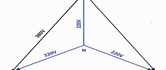
Phase means a change in direction between the magnitudes of the electrical network at the same point in time. In the case of 3 f. current, use three voltages oriented in 3 different directions. Thus, the network voltage is calculated by adding vector quantities, and is not equal to the algebraic sum of all voltages.
Let's look at the example of the same engine. When applying 380 V to the coil, different phase pairs are used in a specific sequence for each winding. This is actually why the circuit is characterized by 380 Volts, and not by scalar addition (220 + 220 + 220 = 660)V. This explanation is very simplified and not entirely complete, but hopefully well presented. Yes, and it is written so that it is clear to us, electric “teapots”.
In technical terms, in a three-phase electrical network, circuits of conductors carry three variable values of physical quantities that reach instantaneous peaks at different times. Taking one conductor as a reference, the other two flows are delayed in time by one third and two thirds of one current cycle. This delay between phases has the effect of transferring power during each cycle and also allows the production of a rotating magnetic field.
Example 1. 10kW 3in1 UPS.
3 in 1 in the UPS name means three-phase input and single-phase output (input - L1, L2, L3, N, and output L and N). Such an uninterruptible power supply combines the power of three phases into one. This gives a lot of advantages:
- Absolutely symmetrical load on the input mains and/or three-phase generator. This results in minimal load on the neutral conductor and eliminates phase imbalance, which leads to voltage surges.
- It becomes possible to realize all the allocated power for the site, because in the usual case, the total power is divided into three lines, but in our case it is all summed up into one stream.
- There is no highly dangerous linear voltage of 380V in the house; everywhere we have only phase voltage of 220V.
The disadvantages include the inability to connect three-phase motors (for example, three-phase air conditioning, ventilation units, powerful pumps) to such a UPS. We usually connect such loads bypassing the UPS or installing an uninterruptible power supply with a three-phase output.
10 kW UPS with 16 55 Ah batteries for the whole house with an estimated autonomous operation of about 5.5-6 hours at an average long-term load of 1.4 kW.
10 kW UPS for the whole house with battery
The UPS allows serial connection of 16 to 20 external batteries. The battery capacity is calculated based on the calculated data on the average load and the required battery life.
Winding connection methods
Engines in everyday life and in amateur practice drive a variety of mechanisms - a circular saw, an electric plane, a fan, a drilling machine, and pumping equipment. Without knowing how electric motors work, it is better not to get into the weeds with frequency drives. Engines are:
- permanent
- and alternating current (asynchronous and synchronous).
The mechanism includes a rotor and a stator. The principle of electromagnetic induction, studied in school, underlies the principle of their operation. Most of the electric motors produced are “asynchronous”. Where did this word come from? The rotation frequency of the moving part (rotor) always lags behind the rotation frequency of the magnetic field of the stationary part (stator). The output frequency scale varies - 1000, 1500, 3000... rpm. And all because the rotor is able to rotate on the shaft at different speeds inside the core.
Depending on the number of poles, the units are one-, two-, or three-pole. In the stator core of the latter there is a winding for each phase, the ends of which are brought out to the terminal box. How can you increase the speed of an asynchronous motor (IM) without losing power? By changing the number of pole pairs.
To move on to other methods, and there are two more of them, we cannot do without the symbols “star” and “triangle”. The three windings of the coil can be connected in two ways: at a point or in a circle, hence the names of the connections “star” and “triangle”.
What happens if a three-phase motor connected by a triangle is connected to a 380 V power supply? In this case, the starting current values can increase seven times, which will lead to network overload. When dealing with engines, you need to be extremely careful. When buying a product, be sure to think about whether the nameplates show a triangle/star icon (and not vice versa star/triangle) at the same voltage of 220/380 V.
How does a 3-phase inverter work?
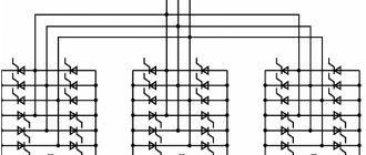
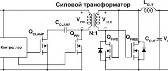
The power part of the three-phase inverter includes transistor switches marked from VT1 to VT6 in the amount of six elements and reverse current diodes VD1–VD6, also six pieces. The diodes are connected into a common bridge and connected in parallel with the power source.
The three-phase power circuit of inverters can be constructed in different ways. With a constant circuit structure, control signals are supplied simultaneously to three power transistors at once. Thus, its structure remains unchanged. In the case of using a variable structure, the number of transistors for supplying control signals is often less than three.
The duration of switching performed by transistor switches and the frequency of the output voltage depend on the control system used. In an interval that includes one period, switching at the output of transistors of the anode and cathode groups can occur from one to many times.
The output current configuration is obtained according to the load characteristics. If the load is active-inductive, the result is a shape in the form of a broken curve, divided into four parts located at half the period. The effect of the current load is determined by integrating the most characteristic sections of the current curve. The required load shape, including sinusoidal, is obtained by repeatedly turning on and off controlled valves within one period.
The output voltage in the inverter is adjusted using pulse width modulation - PWM. The formed modulation in the form of a rectangle is called pulse-width regulation - WIRE. This regulation of the output voltage is performed by varying the duration of the load connection to the power source. This circuit is used during the pause between pulses, when two identical power transistors are locked.
How to connect a three-phase motor to a 220 V network
The use of a three-pole AD in a single-phase electrical network is of interest to many owners of private houses. The units are increasingly in demand in households. They are quite simple in design and easy to use. However, in terms of connecting the motor to a single-phase network, not everything is so simple.
The pulsating field of a single-phase current is not capable of causing the rotor of an electric motor to rotate - such a current must be converted into multiphase and then only supplied to the unit.
You should not pay attention to rationalization proposals using LATRs and other home-made structures. We are not involved in the field of transcendental nanotechnology and science fiction; we cannot count on fees for the support of “Nobel laureates.” Today, there are two sensible ways to convert single-phase current into multiphase - this is connecting the unit through:
- phase shifting capacitor;
- a frequency converter.
Let's look at them one by one.
- Phase shift using capacitors
In three-phase circuits, creating a rotating magnetic field is not a problem; during energy generation, an EMF is induced in the stator windings due to the rotation of the magnetized rotor. Some manage to resort to simple “tricks”. Various schemes are used, for the compilers of which the main question is to ensure the operation of electrical equipment without loss of power. For example, there is a method of shifting the phases in the windings relative to each other.
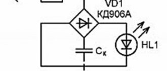
It is enough to connect a capacitor in parallel with one of the windings, first selecting the device rating in such a way as to ensure the necessary phase shift. This option is not bad if you follow the old rule: the fewer and simpler the parts, the more reliable the system as a whole. The capacitor, of course, is a relatively cheap thing, it can be installed in a minute, but it requires special skills. But the second method with a converter, although a little expensive, pays off in convenience. Agree, this is a very important factor.
- Frequency generators operating from a single-phase network
The frequency in our network is constant and equal to 50 Hz. The frequency converter is used to convert single-phase alternating current of 50 Hz into three-phase, with a frequency from 1 to 800 Hz. The entire process technology comes down to controlling the rotation speed of an asynchronous electric motor. Connecting the inverter means choosing the correct cable cross-section, wire types, and additional equipment. Do not think that by opening the page in the instructions, the essence will immediately become clear to you. You may not even achieve the result by connecting the wires according to the diagram if you do not pay attention to some nuances. For what exactly?
Do-it-yourself converter from one to three phases.
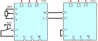
Since the three-pole motor needs to be powered through a state of emergency from a single-phase network, two cables are needed: to the frequency converter, a two-wire one (up to 50 m, you can only use an unshielded cable, shielded - up to 15 m), from the frequency converter to the motor, only a three-wire cable. One of the wires is grounding, the rest are phase. The cross section is selected according to the technical data sheet for the frequency generator. The required voltage in the wires is obtained from the current and resistance (according to the cross-section) of the cable using the familiar formula: U = R*I. Calculation data should be taken according to the PUE.
It is recommended to buy a frequency generator with a double margin, at least 2 kV. Its nominal value is designed only for the power of the machine, which means that at best it will turn off due to heat, at worst it will smoke. All of them are assembled according to the same circuit, using two thyristors controlled by a multivibrator. The scheme is simple. It is better to choose a simple and more powerful one. Buy where there is a choice and always with a guarantee.
Example 4. Three-phase 60 kW 3in3 UPS with long battery life.
The UPS in this example has a modular architecture that allows one power module to be put to sleep if the load does not exceed 50% of the rated power. The modules can also operate in parallel, which increases the reliability of the UPS (N+1 hot standby system). 38 120Ah batteries were installed in a special cabinet and will provide a battery life of more than 20 hours with an average load of 2.5kW.
Powerful three-phase UPS for home
I will be happy to answer your questions in the comments!
- You can get a consultation by phone: +7 (495) 120-80-02
- Requests and projects for calculation can be sent by email
Frequency converter 220-380, whose company is better?
Let's answer the question to the point. There are countless Asian manufacturers on the sales market of such equipment. Let's stop listing. The domestic emergency assembler is a kind of lottery (sometimes it depends on what day of the week the device is assembled).
Frequency drivers from Siemens usually fully meet the requirements. Products produced by ABB or Danfoss are quite easy to set up. It is better than others in terms of price and quality. Buy without hesitation. Judging by the reviews, they have a very decent device. Dynamic performance is enhanced by vector control, which also provides high torque at low frequencies during starting and running.
Universal compact CP models do an excellent job of converting network parameters; their obvious advantages are expressed in the following:
- the ability to generate “full” three-phase current;
- no loss in engine power;
- Suitable for any electric motor design;
- The constructivity is very simple.
- own energy consumption is minimal.
Example 3. Three-phase UPS for 40 kW 3in3.
UPS with three-phase input and three-phase output are installed if an output power of more than 20 kW is required, as well as in the presence of full-fledged three-phase consumers that require guaranteed power supply.
In this project, the task of the UPS was to completely stabilize the input voltage and provide uninterruptible power supply during the startup and warm-up of the three-phase RID diesel generator. The UPS with battery cabinet was installed on a hydraulic accumulator on a special reinforced rack:
UPS 40 kW for working with diesel generator set
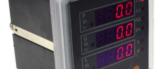
The UPS has a color touchscreen monitor that displays all the necessary system operating parameters and records the history of network events:
UPS Monitor
The UPS already has a built-in network card that allows you to remotely monitor the status of the network and load via the IP protocol.
Where frequency converters are used single-phase input-output 1 ph. 220 V
Asynchronous motors (AM) are more often used in everyday life than in industry, in particular in the system of single-pole duct fans and water pumps. It is no secret that difficulties arise associated with adjusting the rotation speed of blood pressure. This is the task of single-pole input-output frequency converters 220-220.
Uneven torque may cause abnormal noise and vibration in the unit. To regulate the speed of three-phase electric motors, single-pole 220/380 V frequency changers (input/output) are used, sometimes with a special controller used to control the device.
These types of converters are intended for use in technological (pumps and fans, transport mechanisms, extruders, mixers, etc.) and energy-saving equipment (pump control stations, climate and air conditioning systems, etc.). Models are available with the possibility of mounting on a DIN rail. They have a wide range of output frequency adjustment. The smart control panel provides a comfortable working environment.
In order to avoid complications that are often encountered during the operation of 3-pole electric motors in single-phase networks, you should adhere to the following rules:
- the power of the engine used as a state of emergency is selected greater than the power of the electric drive connected to it;
- in practice, 4 kW converters are capable of solving all existing economic problems in a private home. You can focus on a load of 2-3 kW, which is acceptable for the power grid;
- the operating current of the converter in normal mode must be greater than its value indicated in the passport of this type of electric motor (otherwise the power supply will simply burn out);
- The converter is connected in a strict sequence: the emergency starts first, then the 3-pole consumers. The equipment is turned off in the reverse order.
Types of three-phase inverters
According to their parameters, characteristics and purpose, all types of converters can be divided into several groups.
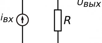
First of all, they can be autonomous or dependent. In the first case, direct current is converted into alternating current, where the frequency is determined by the control system, and the characteristics of the output voltage are closely related to the load parameters. Dependent devices produce a current determined by the frequency of the local network, with constant values. In autonomous devices, smooth voltage changes from zero to the highest permissible value are possible. Therefore, such inverters are most often used in various circuits.
Principle of operation
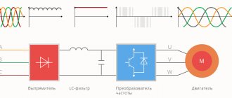
A frequency converter for a PWM induction motor is essentially a double voltage conversion inverter.
The input diode bridge rectifies the mains voltage 220 or 380V, and then smoothes and filters it through a capacitor.
Next, using input bridge switches and microcircuits, a sequence of electrical signals of a certain frequency and duty cycle is formed from direct voltage. Thus, beams of rectangular pulses are formed at the output of the frequency converter. However, due to the inductance of the windings of an asynchronous motor, they turn into a voltage similar to a sinusoidal one.
The device also has a microprocessor that allows you to perform tasks such as:
Most frequency converters for asynchronous motors are based on double conversion. Among them there are two main classes:
Each type of frequency generator is designed to operate under certain conditions, which dictate the choice and appropriateness of use in a particular situation.
Controlled rectifiers provide direct communication by triggering groups of thyristors and supply voltage to the motor winding.
Voltage conversion in this case is carried out by cutting out sinusoids from the input current. In this case, the resulting frequency is in the range from 0 to 30Hz. This use case is not suitable for variable speed drives.
To use non-lockable thyristors, it is necessary to create a more complex control system, which increases the cost of the created circuit.
Otherwise, a sine wave on input may result in:
In addition, compensators increase the cost of the chain, dimensions and weight, and losses reduce efficiency.
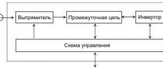
Another class includes power circuits that use frequency converters for asynchronous motors with an intermediate link. They provide the conversion of electrical current in two stages.
In the first stage, a sinusoidal voltage with constant frequency and amplitude is converted through rectification. In this case, special filters are used to smooth the indicators.
At the second stage, through an inverter at the output, energy is converted with a variable frequency and amplitude.
Frequency converters for asynchronous motors operating as a thyristor have the following advantages:
- provide the ability to work in systems with high current levels;
- such a system is intended for use where there are high current levels;
- they are resistant to heavy loads and impulse effects;
- provide high efficiency, reaching 98%.
Connection diagram for a frequency converter to a single-phase motor
An asynchronous motor today is one of the most common and sought-after devices that drives various types of machine drives that are used in different areas of production.
Expert opinion
It-Technology, Electrical power and electronics specialist
Ask questions to the “Specialist for modernization of energy generation systems”
Features of constructing a frequency converter circuit for controlling an asynchronous three-phase motor However, despite their high popularity and justification for use, asynchronous motors have a significant drawback. Ask, I'm in touch!