Advantages and disadvantages
Like everything material, three-phase current has its pros and cons. The positive aspects of using systems with three or four wires include:
- efficiency. To transmit electricity over long distances, cores made of non-ferrous metals with low resistivity are used. The voltage is divided proportionally to the number of cables. By distributing loads, engineers can reduce the number of wires and their cross-section, which, given the cost of rare materials, provides noticeable savings;
- efficiency. The power parameters of three-phase transformers are an order of magnitude higher than single-phase transformers with smaller magnetic core sizes;
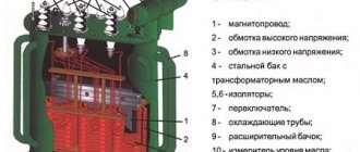
3-phase current transformer
- simplicity. When consumers are simultaneously connected to a three-phase system, an additional electromagnetic field is generated. The phase shift effect has made it possible to create simple and reliable brushless electric motors, the rotor of which is made according to the principle of a conventional blank and is mounted on ball bearings. Asynchronous electric drives with a squirrel-cage rotor are widely used as power units. The main advantage of such motors is the ability to change the direction of rotation of the axis by switching to different phase wires;
- variability. In circuits with several phases, it is possible to obtain different voltages. The user will be able to change the power of the heater or servo drive by switching from one cable to another;
- reducing the stroboscopic effect. It is achieved by independently connecting different lamps to individual phases.
Along with its advantages, three-phase current has its disadvantages. They include:
- connection difficulty. To connect a three-phase network to a private or industrial building, you must obtain special permission and technical specifications from the local energy sales company. This event is quite expensive and troublesome. Even if all conditions are met, a positive result is not always guaranteed;
- application of enhanced security systems. The three-phase network supplies a voltage of 380 V, so additional devices for protection against electric shock and short circuits are required, which can lead to fire. In such cases, another three-pole circuit breaker with higher ratings is installed at the input. It will help avoid fire in the event of a short circuit;
- the need to install auxiliary modules to limit overvoltage in the distribution board. It is necessary in case the neutral cable breaks, which will lead to an increase in voltage in one of the phases.
The transition to three-phase current is advisable for owners of premises whose area is more than 100 square meters. meters. This applies to private homes and industrial buildings. This connection scheme will allow you to redistribute the load evenly across all consumers and avoid power surges.
Elements and details
The detailed heating scheme for a two-story house consists of the following parts:
Boiler where heat generation occurs. The required performance is one hundred watts per square meter (the walls in the room do not exceed three meters in height). A reserve is provided (up to 50 percent). It is necessary in order to heat the living space, even if there are unaccounted losses of thermal energy. Boilers operate on diesel fuel, coal, peat, gas, electricity, and wood. Gas and electric are considered the most convenient in everyday life (average price is about 50 thousand rubles). Such units are more expensive than those heated with wood (the average price is about 30 thousand rubles), but they are characterized by high productivity and do not require large expenses during operation. Gas for the boiler is connected using a cylinder or gas pipeline system. Material of manufacture – cast iron, steel. Mount on the floor or wall. Floor-standing equipment requires a separate utility room equipped with a chimney; wall-mounted equipment operates without a passage for smoke and a utility room. The heating scheme for a 2-story private house is developed with single-circuit equipment - only to provide heat; double-circuit – for heating and supplying hot water to the user. The dual-circuit unit has a circulation pump and a tank.
A double-circuit boiler consists of a pump and a tank
Heat carriers in the system. They are water, electrolytes or antifreeze. If people live in the building permanently, then it is more advisable to use water. In this case, the heating system cannot be stopped during the cold season. If the building is used occasionally (dacha, temporary housing), then antifreeze or electrolyte is used. The coolant is determined at the stage of developing a scheme for the house.
- Heating devices. Radiators or batteries are made of steel, aluminum, cast iron or mixed materials. The wider the battery, the greater its heat dissipation. To make it more convenient to operate the radiator, it must have an air vent to release the air that gets inside; thermoregulatory valve to ensure uniform heat removal; shut-off valve to make servicing the unit easier. How to conduct heating - you can connect the batteries with a one-sided, diagonal or bottom wire. When determining the number of batteries in a room, take into account:
- room area;
- section power (indicated in the equipment passport);
- are there plastic windows;
- are there any heat losses on the external walls;
- How is the roof insulated?
- what is the height of the ceilings.
- Pipeline. It is necessary to transfer, distribute and return the coolant to the boiler. The circuit is closed. It ensures tightness. Pipes are made of steel or polypropylene. There are roughness inside to hold the heat carrier in one place for a certain period of time (from 30 minutes to 12 hours).
- Expansion tank. Allows you to avoid possible destruction due to a pressure surge or gas release. Inside there is a membrane dividing the tank into two chambers: water and air. The equipment must be insulated with mineral wool, for example, to avoid heat loss and “defrosting”.
- Shut-off valves. Taken into account when developing a heating wiring diagram. Allows you to disconnect a section of the pipeline to carry out restoration.
- Fittings for protection. If the power goes out or the volume of gases is exceeded, the fittings will stop the system or its section until the problem is completely eliminated. Consists of valves, valves, air vent.
- Regulating fittings to equalize the indicators. Consists of valves, tap.
- Distribution manifold. In a heating scheme for a two-story house, it is needed to eliminate heat loss and distribute the load. Safety devices are installed on it - from pressure gauges to sensors.
Distribution manifold will help you save on heat bills
Pump for circulating coolants. Without it, when heating a two-story private house with your own hands, the heat will not reach the 2nd floor of the building. The larger the area of the building, the more powerful the pump should be installed inside.
Measuring power with a wattmeter
The power consumption of three-phase current is measured using wattmeters. This can be a special wattmeter for a 3-phase network, or a single-phase one connected according to a specific circuit. Modern electricity metering devices are often made using digital circuitry. Such designs are characterized by high measurement accuracy and greater capabilities for operating with input and output data.
Three-phase digital wattmeter
Measurement options:
- Star connection with neutral conductor and symmetrical load - the measuring device is connected to one of the lines, the readings taken are multiplied by three.
- Asymmetrical current consumption in a star connection - three wattmeters in the circuit of each phase. The wattmeter readings are summed up;
- Any load and delta connection - two wattmeters connected in a circuit of any two loads. The wattmeter readings are also summed up.
Measurement schemes
In practice, they always try to make the load symmetrical. This, firstly, improves network parameters, and secondly, simplifies the accounting of electrical energy.
Electric meter
For any connection scheme, an electricity consumption meter is required. A 3-phase meter can be connected directly to the network (direct connection) or through a voltage transformer (semi-indirect), where the device readings are multiplied by a coefficient.
It is important to follow the connection order, where odd numbers are power and even numbers are load. The color of the wires is indicated in the description, and the diagram is located on the back cover of the device
The input and corresponding output of a 3-phase meter are indicated by the same color. The most common connection order is when the phases come first and the last wire is zero.
A 3-phase direct connection meter for a home is usually designed for a power of up to 60 kW.
Before choosing a multi-tariff model, you should coordinate the issue with the energy supply company. Modern devices with tarifficators make it possible to calculate electricity charges depending on the time of day, register and record power values over time.
The temperature readings of the devices are selected as widely as possible. On average they range from -20 to +50 °C. The service life of the devices reaches 40 years with a calibration interval of 5-10 years.
The meter is connected after the input three- or four-pole circuit breaker.
Calculation of a three-phase circuit connected by a star
A three-phase circuit connected by a star is most conveniently calculated by the two-node method. In Fig. Figure 7.5 shows a three-phase circuit with a star connection. In general, the load phase resistances are not the same (ZA ≠ ZB ≠ ZC)
The neutral wire has a finite resistance ZN. In a circuit, a nodal voltage or neutral bias voltage occurs between the neutral points of the source and load. This voltage is determined by formula (6.2).
Fig.6. 5
(6.2)
Phase currents are determined by the formulas (in accordance with Ohm’s law for the active branch):
(6.3)
Neutral current
(6.4)
Special cases. 1. Symmetrical load. The load phase resistances are the same and equal to a certain active resistance ZA = ZB = ZC = R. Nodal voltage
,
because the three-phase EMF system is symmetrical, .
The load and generator phase voltages are the same:
Phase currents are identical in magnitude and are in phase with their phase voltages. There is no current in the neutral wire
In a three-phase star-connected system, with a symmetrical load, the neutral wire is not needed.
Shown is a vector diagram of a three-phase circuit for a symmetrical load. 2. The load is asymmetrical, RA< RB = RC, but the neutral wire resistance is zero: ZN = 0. Neutral bias voltage
rice. 6.6
The phase voltages of the load and generator are the same
Phase currents are determined by the formulas
The current vector in the neutral wire is equal to the geometric sum of the phase current vectors.
In Fig. Figure 6.7 shows a vector diagram of a three-phase circuit connected by a star, with a neutral wire having zero resistance, the load of which is active resistances of unequal magnitude. Rice. 6.7 3. Unbalanced load, RA< RB = RC, no neutral wire,
The neutral bias voltage appears in the circuit, calculated by the formula:
The generator's phase voltage system remains symmetrical. This is explained by the fact that the source of three-phase EMF has an almost infinitely large power. Load asymmetry does not affect the generator voltage system. Due to the neutral bias voltage, the load phase voltages become unequal. The phase voltages of the generator and the load are different from each other. In the absence of a neutral wire, the geometric sum of the phase currents is zero.
In Fig. Figure 6.8 shows a vector diagram of a three-phase circuit with an asymmetrical load and a broken neutral wire. The phase current vectors coincide in direction with the vectors of the corresponding phase load voltages. A neutral wire with zero resistance in a circuit with an asymmetric load equalizes the asymmetry of the phase voltages of the load, i.e. with the inclusion of this neutral wire, the phase voltages of the load become identical. Rice. 6.8
The procedure for bringing single-phase loads to conventional three-phase power
The loads are distributed among the phases with the greatest uniformity and the amount of unevenness (N) is determined.
, (7)
When H > 15% and switched to phase
voltage:
where Р
у (3)
is the conditional reduced three-phase power, kW;
R mf (1
) – single-phase load of the most loaded phase, kW.
At H >15% and switched to linear
voltage:
for one electrical receiver:
R y (3)
= R nb.f. (
19)
for several electrical receivers:
Single-phase
electrical receivers connected to phase and phase-to-phase voltages and distributed among phases with unevenness not exceeding 15% (N ≤ 15%) are taken into account as three-phase of the same total power (the sum of all single-phase loads).
Note.
Calculation of electrical receivers of intermittent short-term mode is carried out after reduction to long-term mode.
When switching on electrical receivers to phase voltage:
, (11)
where S pv
– nameplate power, kVA;
R nom.f
– rated power of the maximum loaded phase, kW.
When switched on to linear voltage, the loads of individual phases of single-phase electrical receivers are determined as half-sums of two arms adjacent to a given phase (Fig. 1).
(12) (13)
(14)
From the results obtained, the largest value of Rf is selected. nb.
When single-phase loads are connected to phase voltage, the load of each phase is determined by the sum of all connected loads on this phase (Fig. 2).
Example 2:
Three single-phase welding transformers with the passport data indicated below are connected to a voltage of 380 V. Determine the conditional three-phase rated power P nom.y if:
Solution.
Rated reduced power of transformers:
P nom.1
= S 1∙∙ cosφ 1 = 80∙
= 28 kW;
P nom.2
= 30∙∙ 0.53 = 13 kW;
R no.3
= 32∙
∙0.54 = 14 kW.
Load of the most loaded phase when transformers are switched on to the corresponding phases:
Uneven phase loading:
The most loaded phase is phase A: P a
= P nom.ph = 21 kW.
Conditional three-phase rated power: P nom.y
= 3P a = 3∙21= 63 kW.
Calculation of a three-phase circuit connected by a star
A three-phase circuit connected by a star is most conveniently calculated by the two-node method. In Fig. Figure 7.5 shows a three-phase circuit with a star connection. In general, the load phase resistances are not the same (ZA ≠ ZB ≠ ZC)
The neutral wire has a finite resistance ZN. In a circuit, a nodal voltage or neutral bias voltage occurs between the neutral points of the source and load. This voltage is determined by formula (6.2).
Fig.6. 5
(6.2)
Phase currents are determined by the formulas (in accordance with Ohm’s law for the active branch):
(6.3)
Neutral current
(6.4)
Special cases. 1. Symmetrical load. The load phase resistances are the same and equal to a certain active resistance ZA = ZB = ZC = R. Nodal voltage
,
because the three-phase EMF system is symmetrical, .
The load and generator phase voltages are the same:
Phase currents are identical in magnitude and are in phase with their phase voltages. There is no current in the neutral wire
In a three-phase star-connected system, with a symmetrical load, the neutral wire is not needed.
Shown is a vector diagram of a three-phase circuit for a symmetrical load. 2. The load is asymmetrical, RA< RB = RC, but the neutral wire resistance is zero: ZN = 0. Neutral bias voltage
rice. 6.6
The phase voltages of the load and generator are the same
Phase currents are determined by the formulas
The current vector in the neutral wire is equal to the geometric sum of the phase current vectors.
In Fig. Figure 6.7 shows a vector diagram of a three-phase circuit connected by a star, with a neutral wire having zero resistance, the load of which is active resistances of unequal magnitude. Rice. 6.7 3. Unbalanced load, RA< RB = RC, no neutral wire,
The neutral bias voltage appears in the circuit, calculated by the formula:
The generator's phase voltage system remains symmetrical. This is explained by the fact that the source of three-phase EMF has an almost infinitely large power. Load asymmetry does not affect the generator voltage system. Due to the neutral bias voltage, the load phase voltages become unequal. The phase voltages of the generator and the load are different from each other. In the absence of a neutral wire, the geometric sum of the phase currents is zero.
In Fig. Figure 6.8 shows a vector diagram of a three-phase circuit with an asymmetrical load and a broken neutral wire. The phase current vectors coincide in direction with the vectors of the corresponding phase load voltages. A neutral wire with zero resistance in a circuit with an asymmetric load equalizes the asymmetry of the phase voltages of the load, i.e. with the inclusion of this neutral wire, the phase voltages of the load become identical. Rice. 6.8
Determination of conditional three-phase power created in a three-phase network by single-phase electric motors
Today is a very important topic for designers, in which I will present my updated program. When calculating electrical loads, it is necessary to reduce the power of single-phase electrical equipment to conventional three-phase power in accordance with RTM 36.18.32.4-92.
If you are not familiar with my program for calculating electrical loads, then first I advise you to familiarize yourself with what came before.
In the previous version of the program, the conditional three-phase power had to be calculated on a calculator and keep in mind all the conditions for bringing the power of single-phase electric vehicles to the conditional three-phase power.
As I already mentioned, I am currently reworking my programs and decided to expand the functionality of the program for calculating electrical loads.
Compared to the old program, here I changed the color scheme, added a current calculation for motors and a form I developed for calculating conditional three-phase power created in a three-phase network by single-phase electrical receivers.
The calculation sequence is best seen with an example.
Let's say we need to calculate the estimated power, current consumption, and power factor of an electrical panel to which the following three-phase and single-phase electric motors are connected:
Name of electronic signature
3Р/1Р
Quantity, pcs.
R, kW
cosϕ
How to determine the conditional three-phase power created in a three-phase network by single-phase electric motors?
RTM 36.18.32.4-92 says only the following about this:
3.2.1.7. If there is a group of single-phase EDs that are distributed among the phases with unevenness not exceeding 15% in relation to the total power of three-phase and single-phase EDs in the group, they can be presented in the calculation as an equivalent group of three-phase EDs with the same total rated power.
If the specified unevenness is exceeded, the rated power of the equivalent group of three-phase electric power plants is assumed to be equal to the triple value of the power of the most loaded phase.
You have to figure out the rest yourself, because... clear instructions for calculation are not provided. But what to do when different utilization factors and power factors, electric power capacities differ significantly from each other?
After all the reflection and communication with my colleagues, I came to the conclusion that single-phase electric power supply should be reduced to three-phase power, taking into account the effective number of electric power supply and as a result we should get the equivalent of not one, but the N number of three-phase electric power supply, which correspond to the power of single-phase electrical receivers our shield.
Appearance of the updated program:
Calculation of the input device.
Calculation of the input device
Distribution board calculation.
Distribution board calculation.
Determination of conditional three-phase power created in a three-phase network by single-phase electric motors.
Determination of conditional three-phase power created in a three-phase network by single-phase electric motors.
I will tell you the procedure for calculating electrical loads, including the determination of conditional three-phase power, in my next video.
I look forward to your comments and suggestions.
PS I also use this program when calculating administrative buildings.
See the conditions for receiving the program on the MY PROGRAMS page.
Why are there usually three phases and not four?
Almost all novice electricians ask this question. In fact, the number of phases is unlimited. There can be 1, 2, 3, 4 and even 10. However, three-phase systems are widely used. This is due to the fact that such a circuit is sufficient to solve most problems.
Such systems are mostly used for power plants in production. The rotor rotation is 360 degrees, and the phase shift is 120 degrees. It is quite enough to spin the armature to the required speed and get the required power from the engine. Increasing the number of phases will only increase the cost of the installation itself, since it will require installing additional coils and connecting extra cables.
Important! Adding phases to the existing three does not increase the efficiency of the unit or increase its power. From a rational point of view, this only adds to the cost of installations while maintaining the same operating parameters
Three-phase AC system
Three-phase system networks are designed for power from substations that supply voltage through four wires: three phases and zero. This is one of the special cases of multiphase circuits where EMFs operate, having sinusoidal shapes and equal frequency. They are produced by the same source, but have a phase angle of 120 degrees (2π/3).
Another electrical engineer M.O. Dolivo-Dobrovolsky, while studying the operation of asynchronous motors, presented a four-wire system as a working system for powering this type of machines and units. Each wire that forms a separate circuit within this system is called a “phase”. The structure of three phase-shifted alternating currents is called three-phase current.
Four-wire power circuit
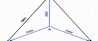
Important! In such a structure, the phase voltage is 220 V - this is what the device will show when measuring between the phase and neutral conductors. The linear voltage will be 380 V when measuring between two phase current conductors
Three-phase circuit concept
So, a three-phase electrical circuit is a circuit in the branches of which there are three EMFs varying in time according to a harmonic law (sinusoidal law) with the same frequency, but having a phase shift relative to each other by an angle equal to 2π/3 (120).
To obtain a three-phase harmonic signal, three-phase synchronous generators are used, in the three stator (armature) windings of which these EMFs are induced.
With the positive directions of the EMF indicated in the figure below (from the ends of the phases x, y, z to their beginnings a, b, c):
The emf will change according to the expressions below:
ea = Еam sin ωt,
Below are graphs of changes in these values over time:
When combining the EMF vector Ea with the axis of real values of the complex plane:
We obtain expressions for the EMF presented in complex form:
It should also be noted that the EMF Ea is usually directed upward vertically when constructing vector diagrams, which, in turn, corresponds to a rotation of the complex plane by 90 counterclockwise. In this case, the axes of imaginary and real quantities may not be indicated:
Using the positive direction and having information about the laws of change in EMF or having the corresponding graphs, you can determine the actual directions and instantaneous values of the EMF at any time. So, for example, at t = 0, ea = 0, a:
In the case when eb < 0 and ec > 0, then at t = 0 the emf ec and eb will be directed in different directions.
If you look at graph b), which shows a three-phase harmonic signal, you can see that phase A will reach its maximum value first, then phase B, and only then phase C. This sequence of phases reaching their maximum (amplitude) values is called a direct sequence of alternation phases If the rotor of a synchronous generator rotated in the opposite direction, then the phase sequence would be reverse C-B-A, and this would be a reverse phase sequence. The direction of rotation of both three-phase asynchronous electric machines and three-phase synchronous machines directly depends on this sequence. Calculations and analysis of three-phase circuits are usually carried out under the assumption that the system has direct phase rotation.
Power measurement
Wattmeters, special devices designed for this purpose, allow you to measure the power of three-phase circuits. Their number and connection methods depend on the specific electrical circuit: its characteristics and load connection diagram. Three-phase networks are distinguished by the number of supply wires and load distribution across phases, namely:
- three-wire system;
- four-wire system;
- uniform load;
- asymmetrical load.
Symmetrical load
If the system consists of four wires (3 phases and “zero”), and the load is evenly distributed between the phases, then in order to find out the total amount of power, it is enough to have one measuring device. The current winding of the wattmeter is connected in series to one of the linear wires, and the voltage winding of the measuring device is connected between the linear and neutral wires. This type of connection makes it possible to find out the number of watts in one phase. And since the load in the system is distributed evenly, the resulting power of the three-phase network is found by multiplying the obtained readings by the number of phases, that is, by 3.
Uneven distribution of consumers
Circuits with unbalanced loads on phases require the use of several wattmeters to determine the power characteristics. In a system consisting of four wires, you need to connect three devices so that the voltage windings of each are connected between the neutral wire and one of the phases. The overall result is found by summing the individual readings of each wattmeter.
A three-wire system will require a minimum of two wattmeters to determine the power of the entire circuit. The voltage windings of each individual wattmeter are connected to the input current clamp and the remaining free linear wire. The resulting readings are added up and the value of this value is obtained for a three-phase circuit. This circuit for connecting measuring instruments is based on Kirchhoff's first law.
Such nuances are very important when designing a three-phase network for the private sector. They should also be taken into account when properly servicing existing power supply systems.
Features of connecting power to a private home
Many people believe that a three-phase network in the house increases power consumption. In fact, the limit is set by the electricity supply organization and is determined by the following factors:
- supplier capabilities;
- number of consumers;
- condition of the line and equipment.
To prevent voltage surges and phase imbalance, they should be loaded evenly. The calculation of a three-phase system is approximate, since it is impossible to accurately determine which devices will be connected at a given moment. The presence of pulsed devices currently leads to increased energy consumption during their startup.
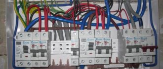
The electrical distribution panel for a three-phase connection is larger in size than for a single-phase supply. Options are possible with the installation of a small input panel, and the rest made of plastic for each phase and for outbuildings.
Connection to the main line is carried out using underground and overhead lines. Preference is given to the latter due to the small amount of work, low connection cost and ease of repair.
Nowadays it is convenient to make an air connection using a self-supporting insulated wire (SIP). The minimum cross-section of an aluminum core is 16 mm2, which is sufficient for a private home.
The SIP is attached to the supports and the wall of the house using anchor brackets with clamps. The connection to the main overhead line and the input cable to the electrical panel of the house is made with branch piercing clamps. The cable is taken with non-combustible insulation (VVGng) and passed through a metal pipe inserted into the wall.
Three-phase and single-phase current
The “Y” circuit configuration makes it possible to use two different voltages when powering consumers in domestic and industrial networks: 220 V and 380 V. 220 V is obtained using two conductors. One of them is phase, the other is N-conductor.
The voltage between them corresponds to the phase voltage. If you take 2 conductors, both representing phases, then the voltage between the phases is called linear and is equal to 380 V. All 3 phases are used for connection.
Voltage distribution in single-phase and three-phase systems
The main differences between single-phase and three-phase systems:
- Single-phase current involves power through one conductor, three-phase - through three; To complete a single-phase power circuit, 2 conductors are required: one more neutral, for three-phase - 4 (plus neutral); The greatest power is transmitted through three phases, in contrast to a single-phase system; Single-phase network simpler; If a phase wire malfunctions in a single-phase network, the power is completely lost, in a three-phase network it is supplied through the two remaining phases.
Interesting. Nikola Tesla, the discoverer of polyphase currents and inventor of the induction motor, used a two-phase current with a phase difference of 90°. Such a system is suitable for creating a rotating magnetic field more than single-phase, but less than three-phase. The two-phase system first became widespread in the United States, but then completely disappeared from use.
Today, almost all electrical power supply is based on low-frequency three-phase current using individual phases in parallel.
Almost all power plants have generators that produce three-phase current. Transformers can operate with three-phase or single-phase current. The presence of reactive power in such networks requires the installation of compensating equipment.
How does a generator work?
The device works by converting rotational energy into electrical energy. The electric machine, using the rotation of the MP, generates electric current. At the moment when the wire winding (coil) rotates in the MF, the magnetic field lines penetrate the turns of the winding.
Attention! As a result of this process, electrons move towards the positive pole of the magnet. In this case, the current moves, on the contrary, towards the negative magnetic pole
It doesn’t matter what rotates under mechanical action, a winding or a magnetic field, the current will flow as long as the rotation is performed. Generators producing three-phase voltage may have:
Generators producing three-phase voltage may have:
- fixed magnets and a movable (rotating) armature;
- a stationary stator and magnetic poles that rotate.
In devices of the first design, there is a need to draw a large current at a high voltage. To do this, you have to use brushes (contacts sliding along slip rings).
The second generator structure is simpler and more in demand. Here the rotor is a moving element and consists of magnetic poles. The stator is a stationary part, assembled from a package of iron sheets insulated with each other and inserted into the grooves of the stator winding.
Information. The rotor has a body made of solid iron and has magnetic poles in the form of tips. Tips are assembled from separate sheets. Their shape is selected so that the generated current is close to a sinusoid in shape.
Pole cores have field coils. The coils are supplied with direct current. The feed is carried out through graphite brushes to the contact rings located on the shaft.
In the diagrams, a 3-phase generator is drawn as three windings, the angle between which is 1200.
There are several ways to excite generators, namely:
- independent - using a battery;
- from the exciter - using an additional generator mounted on one shaft;
- due to self-excitation - its own rectified current.
This also includes magnetic excitation supplied from permanent magnets.
Three-phase alternator
Advantages and disadvantages of a three-phase power supply system
It is no secret that three-phase power supply to a private home is becoming more and more relevant, and this is connected not only with the voltage level. Let's look at all the advantages of 380 Volts and here is a list of them:
- Connection of the most common asynchronous electric motors with a squirrel-cage rotor in everyday life and in production. When connected to a single-phase circuit, their power, torque, and efficiency are lost. After all, they were originally designed for three phases. The use of such electric machines in a private home may be necessary when installing a grinding, drilling or woodworking machine and other types of equipment. An owner who has the skills to operate such equipment will always find a use for it. A powerful pump is always useful at the dacha, so running 380 Volts won’t hurt here either.
- By connecting three phases, the owner of a private house receives, by and large, three independent single-phase networks at once, which he can dispose of at his own discretion. To do this, in order to obtain a single-phase voltage of 220 Volts, you need to connect one wire to the phase and the other to zero. It will be called phase. The voltage between two phases is 380 Volts and is called linear.
- In the event of a breakdown or emergency at a distribution substation, one or even two phases may burn out. At the same time, the owner of a private house with three phases will at least have lighting and a refrigerator working. It must be remembered that for three-phase motors, operation on two phases will entail its inevitable failure.
Keep in mind that there are pitfalls here too. A three-phase network is needed if the power of a single-phase network is not enough. And even if single-phase is not enough, there is no need to rush to connect three phases, it is better to clarify the possibility of increasing the power limit for a single-phase network - this procedure is much simpler than coordinating and connecting three phases. Three phases must be connected if it is necessary to power three-phase electric motors that cannot operate in single-phase mode, or if a large number of electrical appliances and equipment are used simultaneously, for example, if the house has a large household or some small-scale production has been established.
Several other disadvantages of the three-phase power supply system should also be noted. One of the disadvantages is the need to distribute loads evenly across each phase. The second drawback is the great difficulty in connecting, purchasing another shield, protective devices, etc. The third drawback is a great danger from the point of view of electric shock, since the house will have not only a single-phase voltage of 220 V, but also a linear voltage of 380 V
As you can see, the advantages of powering the consumer from a 380 Volt network are not always obvious. Now it’s worth figuring out what documents are needed to connect a three-phase network. This is what we will talk about now.
Determination of design loads taking into account single-phase receivers
Lecture No. 6.
Determination of design loads taking into account single-phase receivers.
At industrial enterprises, along with three-phase power receivers, there are stationary and mobile single-phase current receivers connected to phase or line voltage. When designing, they strive to distribute the power of single-phase receivers evenly across the phases of a three-phase network. However, this is not always possible. It is considered that the phase distribution of single-phase receivers is completed if the total rated power that remains undistributed evenly among the phases does not exceed 15% of the total load of the power supply system unit (the total power of three-phase and single-phase receivers distributed evenly among the phases). If the unevenness exceeds 15%, then the conditional three-phase rated power Rnom is determined. at
unevenly distributed receivers.
When the number of single-phase receivers unevenly distributed across phases is less than four Rnom. at
determined in simplified ways:
When switching on single-phase receivers to phase voltages Rnom. at
taken equal to triple the value of the rated power
Rnom.
m.f maximum loaded phase
Rnom. y=3 Rnom. m.f.
;
When switching on single-phase receivers to line voltage, the conditional three-phase rated power is determined by:
a) with one receiver
Rnom. y= ,
b) with two or three receivers connected to different line voltages of a three-phase network
Rnom. y=3rn. l
,
where is the rn. l
– rated power of the receiver of the most loaded phase.
If the number of unevenly distributed receivers is more than four, then the three-phase rated power is determined as triple the rated power of the most loaded phase. In this case, the most loaded phase is considered to be the phase with the highest average load from single-phase receivers. The average load of each phase with a mixed connection of single-phase receivers (the most general case), when some of the receivers are connected to phase voltage, and some to line voltage, is determined by summing the single-phase loads of this phase (phase-zero) and single-phase loads connected to line voltage, given to this phase and phase voltage using reduction coefficients.
Formulas for converting a single-phase load to a three-phase one:
,
,
,
where Rs. m
– average active load for the busiest shift,
Rn. AC
– maximum linear load,
r(AC)A
– coefficient of reduction of linear load to phase A.
The formulas for reducing reactive power are similar.
The most loaded phase is selected and the three-phase conditional load is determined based on its load:
Rs. m.u=3Rs. m.f. and
;
Qs. m.y=3 Qs.
m.f. ,
where Rs.
m.f and Qs.
mf average active and reactive loads of the maximum loaded phase.
When working together on a three-phase network of single-phase and three-phase electricity receivers, the calculated load of the power supply system node is determined by the formulas:
;
with an effective number of receivers
;
with an effective number of receivers
,
where n1,
m1
– the number of three-phase current receivers with variable and almost constant load patterns;
n2,
m2
- number of single-phase current receivers with variable and almost constant load schedules.
Determination of peak loads.
When designing power supply systems, peak current is considered as the peak load.
The peak current of a group of receivers operating at a lagging current is determined as the arithmetic sum of the largest of the starting currents of the motors included in the group and the rated current of the entire group of receivers minus the rated current of the motor having the highest starting current:
,
where ip. max
– the highest of the starting currents of the motors of the group of receivers, determined according to the passport data;
IP
– calculated current of the receiver group;
Ki. A
– utilization factor characteristic of the motor having the highest starting current;
Inom. max
– rated motor current (reduced to PV=1) with the highest starting current.
If the number of electricity receivers in a group is small and their installed capacities differ significantly from each other, then if there are powerful synchronous motors in this group, the peak current is determined by the formula:
,
where Рср.
m, Qavg.
m – respectively, the average active and reactive loads of the receivers of the group under consideration for the busiest shift;
rsr.
m, qavg.
m – average load of the engine being started for the busiest shift;
Km
– the maximum coefficient for groups of receivers, excluding the starting engine, can be taken equal to the maximum coefficient for active power found for the entire group.
The following is taken as the highest peak current of one receiver: for motors - the starting current, for furnace and welding transformers - the peak current, which is taken according to the passport data. In the absence of passport data, the starting current of asynchronous squirrel-cage and synchronous motors is taken equal to 5 times the rated current, the starting current of DC motors and asynchronous motors with a wound rotor is 2-2.5 times the rated current, the peak current of furnace and welding transformers is not less than 3 times the nominal (without reduction to PV=1).
When a group of motors self-starts, the sum of the starting currents of these motors is taken as the starting current.
Algorithm for determining design electrical loads.
1. Determination of the calculated electrical load of the ED group (the method of ordered diagrams is used).
Groups gather 10-12 EPs per group based on ki
and
cos j
.
neff
is determined for the group , then we find the design load
Рр
for the EP group.
S for all groups and find Рр S
,
Qр S
,
Spр S.
2 Determination of the calculated electrical loads of consumers (shops).
(or by ks
, or static).
If there are loads of different voltages in the workshop, then Рр
determined for consumers of each voltage separately.
3 When determined at higher levels of Рр
You must first take into account
DРр
,
D Qр
– losses in transformers.
To determine power losses in workshop transformers, simplified formulas are used:
,
.
First you need to sum up all the loads across the workshops.
4 Definition of PP
at the RP level.
The main task: each reactive power can be taken from high-voltage sources and we will use LEDs as Q
.
If we use SD, then we take Qn
SD is the power of the source, then:
QRP= Qp-QnSD
.
5 Determination of the design load of the enterprise as a whole.
,
krm
– coefficient of maximum different times.
PP0
– design lighting load.
Qе1
– the most economical reactive power for transmission from power systems to the enterprise power supply system in the maximum load mode.
Qe1=0.3Рр
Qp-( Qe1+ QSD)= Qku.
Qku –
power of compensating devices, i.e. the power that we must obtain from additional sources of reactive power.
— power received from the system.
Qku
=0 – no additional compensating devices are required.
Qku
0 by more than 10%, then the use of extra CU is economically unjustified.
Qku
>0 within 10%, then you can not install reactive power sources. If more, then you need to install a control unit.
The 10% spread can be explained by the fact that Qzap
CLEP.
Get text
Three-phase circuit diagrams
The windings of a generator or transformer in three-phase circuits can be connected to each other according to two schemes:
- star;
- triangle.
Connections are made on the terminal block (boron) of the unit or transformer, where the ends of the windings are brought out.
Jumper connection of windings
Connecting the load to the generator (transformer) can be done according to the following schemes:
- star-star connection using a neutral conductor;
- star-star connection without using a neutral wire;
- star-delta connection;
- "triangle-triangle" scheme;
- delta-star connection.
Attention! This variety of circuits is due to the fact that the generator's own windings and the load's own windings can be connected in different ways. With different types of coupling, different correspondences between phase and linear values are obtained
The connection can be made at the factory when assembling the generator; the second ends of the windings are already brought out to the point where the power cable is connected. Information about the winding connection diagram is applied to a plate attached to the stator of the machine.
On electric motors, transformers or other consumers, the necessary manipulations are also performed to switch winding terminals. In the picture below, the ends of the windings connected by a jumper are marked with a red marker. Blue marker - power phases.
Connections on boron motor
Star connection
The letter designation of the beginning of the windings is “A”, “B”, “C”, the ends are “X”, “Y”, “Z”. The zero point is marked “O”. Each winding has two ends. When connecting “star”, all three winding terminals of the same name (beginning) are connected to each other at one point “O”. The load is connected to the free ends.
Star winding connection diagram
Delta connection
When making this connection, jumpers are placed on the board, turning on the windings in the following sequence:
- the end of “A” - with the beginning of “B”;
- end “B” – with beginning “C”;
- the end of "C" - with the beginning of "A".
The graphic image of the coils becomes similar to a triangle, hence the name.
When they want to use a plug-in asynchronous motor with maximum efficiency, its windings are connected in a triangle. In this case, the phase voltages coincide (Ul = Uph), the line current will be calculated by the formula:
Il = √3*Iph.
When connecting a motor as a load, it is necessary to take into account a number of nuances:
- an increase in power by 1.5 times is achieved;
- the value of the starting current increases 7 times compared to the operating current due to difficult starting;
- a sharp increase in the load on the electric machine shaft will cause a sharp increase in current.
Because of all this, there is a risk of the machine overheating, which does not happen when the load windings are connected in a star configuration. There, the engine is not prone to overheating, and it starts smoothly.
Switching on the windings according to the "triangle" pattern
With two types of winding connection, two types of currents are distinguished and defined: linear and phase. It's easy to remember the differences:
- the current flowing through the conductor that connects the source to the receiver is called linear;
- The current moving through the windings of the source or load is called phase.
It is worth paying attention to the power formulas for various schemes for connecting the source to the load. The current power in a star circuit is determined by the formula:
The current power in a star circuit is determined by the formula:
P = 3*Uф*Iф*cosϕ = √3*Uл*Iл*cosϕ,
Where:
- Uph – phase voltage;
- Uл – linear voltage;
- Iph – phase current;
- Il – linear current;
- cosϕ – phase shift.
The current power in a delta circuit is calculated by the formula:
P = 3* Uф* Iф*cosϕ = √3*Uл*Iл*cosϕ.
For your information
It is necessary to pay attention to linear and phase currents when the generator (source) is loaded asymmetrically when connecting the load
Connections in a three-phase circuit
Selecting the rating of the circuit breaker
Applying the formula I = P/209, we find that with a load with a power of 1 kW, the current in a single-phase network will be 4.78 A. The voltage in our networks is not always exactly 220 V, so it would not be a big mistake to calculate the current strength with a small margin like 5 A for every kilowatt of load. It is immediately clear that it is not recommended to connect an iron with a power of 1.5 kW to an extension cord marked “5 A”, since the current will be one and a half times higher than the rated value. You can also immediately “graduate” the standard ratings of the machines and determine what load they are designed for:
- 6 A – 1.2 kW;
- 8 A – 1.6 kW;
- 10 A – 2 kW;
- 16 A – 3.2 kW;
- 20 A – 4 kW;
- 25 A – 5 kW;
- 32 A – 6.4 kW;
- 40 A – 8 kW;
- 50 A – 10 kW;
- 63 A – 12.6 kW;
- 80 A – 16 kW;
- 100 A – 20 kW.
Using the “5 amperes per kilowatt” technique, you can estimate the current strength that appears in the network when connecting household devices. You are interested in peak loads on the network, so for the calculation you should use the maximum power consumption, not the average. This information is contained in the product documentation. It is hardly worth calculating this indicator yourself by summing up the rated powers of the compressors, electric motors and heating elements included in the device, since there is also such an indicator as the efficiency factor, which will have to be assessed speculatively with the risk of making a big mistake.
When designing electrical wiring in an apartment or country house, the composition and passport data of the electrical equipment that will be connected are not always known for certain, but you can use the approximate data of electrical appliances common in our everyday life:
- electric sauna (12 kW) - 60 A;
- electric stove (10 kW) - 50 A;
- hob (8 kW) - 40 A;
- instantaneous electric water heater (6 kW) - 30 A;
- dishwasher (2.5 kW) - 12.5 A;
- washing machine (2.5 kW) - 12.5 A;
- Jacuzzi (2.5 kW) - 12.5 A;
- air conditioner (2.4 kW) - 12 A;
- Microwave oven (2.2 kW) - 11 A;
- storage electric water heater (2 kW) - 10 A;
- electric kettle (1.8 kW) - 9 A;
- iron (1.6 kW) - 8 A;
- solarium (1.5 kW) - 7.5 A;
- vacuum cleaner (1.4 kW) - 7 A;
- meat grinder (1.1 kW) - 5.5 A;
- toaster (1 kW) - 5 A;
- coffee maker (1 kW) - 5 A;
- hair dryer (1 kW) - 5 A;
- desktop computer (0.5 kW) - 2.5 A;
- refrigerator (0.4 kW) - 2 A.
How to connect a pass-through switch: connection diagrams
Calculation of cable cross-section by power: practical advice from professionals
The power consumption of lighting devices and consumer electronics is small; in general, the total power of lighting devices can be estimated at 1.5 kW and a 10 A circuit breaker is sufficient for a lighting group. Consumer electronics are connected to the same outlets as irons; it is not practical to reserve additional power for them.
If you sum up all these currents, the figure turns out to be impressive. In practice, the possibility of connecting the load is limited by the amount of allocated electrical power; for apartments with an electric stove in modern houses it is 10 -12 kW and at the apartment input there is a machine with a nominal value of 50 A. And these 12 kW must be distributed, taking into account the fact that the most powerful consumers concentrated in the kitchen and bathroom. Wiring will cause less cause for concern if it is divided into a sufficient number of groups, each with its own machine. For the electric stove (hob), a separate input with a 40 A automatic circuit breaker is made and a power outlet with a rated current of 40 A is installed; nothing else needs to be connected there. A separate group is made for the washing machine and other bathroom equipment, with a machine of the appropriate rating. This group is usually protected by an RCD with a rated current 15% greater than the rating of the circuit breaker. Separate groups are allocated for lighting and for wall sockets in each room.
You will have to spend some time calculating powers and currents, but you can be sure that the work will not be in vain. Well-designed and high-quality electrical wiring is the key to the comfort and safety of your home.

