To understand for what operating conditions a particular current or voltage transformer, as well as other types, is intended, special markings of devices are used. Domestic and imported units have different designations. In our country, installations manufactured in accordance with GOST are more often used.
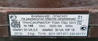
Transformers are marked on a metal shield on the housing. The most common types of transformer symbols will be discussed below.
Information on the case
The information presented on the visible side of the device is applied using engraving, etching or embossing. This ensures the clarity and durability of the inscription. The metal plate contains information about the equipment manufacturer. The year of its manufacture and serial number are applied.
In addition to information about the manufacturer, there must be information about the unit. The number of the standard to which the presented design corresponds is indicated. The rated power indicator must be indicated. For three-phase devices, this parameter is given for each winding separately. Information about the voltage of the coil turns branches is indicated.
The rated current is determined for all windings. The number of installation phases and current frequency are given. The manufacturer provides data on the configuration and connection groups of the coils.
After the above information, you can familiarize yourself with the short circuit voltage parameters. Installation requirements are provided. It can be external or internal.
Technical characteristics allow you to determine the cooling method, the mass of oil in the tank (if this system is used), as well as the mass of the active part. The switch actuator indicates its position. If the installation has a dry type of cooling, there is data on the power of the installation when the fan is turned off.
The serial number must be stamped under the shield. It is present on the tank. The number is indicated on the cover near the HV input, as well as on the top and left on the core beam flange.
Commissioning
The equipment can only be put into operation after preliminary preparation. First, a visual inspection of the unit is performed. There should be no defects on it. The design elements must correspond to the factory configuration.
A visual assessment of oil sealing materials and fasteners is carried out. If necessary, they should be tightened. Oil leaks are unacceptable
You also need to pay attention to the oil level in the tank. The indicator is at the level established by the manufacturer
If necessary, excess will need to be drained. If the coolant level is insufficient, you need to add liquid to the tank.
The insulators are wiped with a dry cloth and gasoline. You need to pour special oil into the thermometer sleeve body. Next you need to mount the measuring device.
If the indicator silica gel is wet, it must be replaced. It is located in the dehumidifier design. The equipment must be connected to ground. This also needs to be checked before starting.
The oil from the cooling system will need to be analyzed. It must meet the established requirements. After this, the plug is isolated. If the oil fluid does not meet the specified requirements, it must be completely drained. A new coolant of appropriate quality is poured into the system.
The resistance of the windings is measured. The switch must be set to the operating position. After this, the equipment can be connected to the network.
Scheme
All data shown on the plate can be divided into 6 groups. In order not to get confused in the information, you should consider the sequence of its writing. For example, installation ATDTsTN-125000/220/110/10-U 1. The following groups are used to mark the features of the device:
- Group I. A - Designed to indicate the type of device (power or autotransformer).
- Group II. T - Corresponds to the type of network for which the device is used (single-phase, three-phase).
- III group. DC – Cooling system with forced circulation of oil and air.
- IV group. T – Shows the number of windings (three-winding).
- V group. N – Voltage is regulated under load.
- VI group. All numbers (rated power, voltage of HV MV windings, climatic version, placement category).
You should learn more about each category. This will make the choice much easier.
Features of operation
Installations of the presented category are operated strictly in accordance with generally recognized standards. Commissioning and monitoring of equipment condition is carried out by trained, experienced employees.
The presented equipment is installed in areas with moderate and cold climates. It is prohibited to store fire hazardous, explosive, chemical substances, gases, or liquids nearby.
The unit is installed at an altitude of no more than 1 km above sea level. The design is not designed to withstand vibration, mechanical shock or shaking. The work cycle is quite long. The equipment is turned off for scheduled repairs and maintenance. If signs of malfunction appear, in an emergency situation, the power is immediately turned off.
The ambient temperature can reach from +40 to -45ºС for category U1. Climatic modification HL1 allows operation in the range from +40 to -60ºС. Relative humidity is 80%. The above conditions contribute to long-term, efficient operation of the equipment.
Having considered the features, operating principles and designations of STMI transformers, you can choose the right device that meets the needs of consumers.
Varieties
The designation of transformers necessarily begins with the type of equipment. If the marking begins with the letter A, it is an autotransformer. Its absence indicates that the unit belongs to the class of power transformers.
The number of phases is required. This allows you to choose an installation operating from a household or industrial network. If the transformer is connected to a three-phase network, the marking will contain a T. Single-phase varieties have the letter O. They are used in household networks.
If the device has a split winding, it will have a P. If there is on-load voltage regulation (OLTC), the device will be marked H on the metal plate. If it is absent, we can conclude that the presented feature is absent in the device.
Maintenance and repair of TMG
Before pouring and topping up oil into the device, it is recommended to check that it has not been used previously. For each batch of oil that is poured and topped up into the device, it is necessary to have quality certificates from the supplier certifying the oil’s compliance with established standards and specifications. Information about the compliance of the oil supplied with the transformer is entered in the passport or transformer form
It is important to note that it is allowed to add oil to the device only with a breakdown voltage of up to 35 kV. Topping up is carried out as necessary
Interesting video: Production of TMG transformers
https://youtube.com/watch?v=fYUtgW0j2S0
Current repairs of transformers are carried out within the time limits established by the governing document “Rules for the technical operation of power plants and networks.” After completion of current equipment repairs, tests are carried out.
From the above description it is clear that TMG is unpretentious to use and requires minimal maintenance costs. In addition, the transformer device has a number of advantages, including an efficiency of up to 99%, excellent performance, as well as protection against overheating and short circuits.
Special designations
Depending on the installation category, special symbols may apply. For a current and voltage transformer, they may not be the same. The second type of technique is used when operating protective mechanisms or for measuring current. The first category of devices is intended to change the value of alternating current.
Voltage transformers do not use high power transmission of electricity. They are capable of creating isolation from low-voltage communications. This category of devices is used in circuits with a voltage of 12V or less. Their main operating parameters are the current and voltage of the primary winding. It is their value that is provided by the manufacturer.
The marking of voltage transformers begins with their design. If this is a walk-through structure, it is designated by the letter P. If it is not there, this is a supporting type of apparatus. The cast insulator is marked L, and the porcelain insulator is marked F. The built-in insulator is marked V.
Decoding of modern current transformers is carried out in the established sequence. It begins with T, which characterizes the devices presented. The installation method can be through-type (P), support (O) or busbar (W). If this device is present in the equipment of power transformers, it is designated as VT. If it is built into the oil switch, then the marking will have the letter B. When installed externally, the device will have an H.
Cooling system
The transformer symbol continues with the cooling method. Today, there are dry, oil-based varieties. Also, the cooling unit may contain a non-flammable fluid dielectric.
Oil varieties include about a dozen different equipment designs. If the circulation of liquid inside is carried out naturally, the device has an M on the panel. If it is forced, the designation D will be present here. It also corresponds to dry varieties of devices with an internal circulation device presented.
If equipment with natural oil movement and forced water flow is installed, it is marked with the combination MV. For devices with forced circulation of non-directional oil flow and natural air movement, a combination of MCs is used. If in such a device the direction of the oil is clearly indicated, the marking will be NMC.
For systems with forced non-directional movement of oil and air, the designation DC is used, and for directional movement - NDC. When the oil moves in the space between the pipes and partitions through which water flows, such a unit has the letter C on the shield. If the oil flows along a directed vector, the device is marked NC.
Cooling system with liquid dielectric
Today, new types of devices with various improved cooling systems are being put into operation. One of them is equipment with a non-flammable liquid dielectric. If cooling occurs through natural circulation, the presented installation is designated by the letter N. If there is forced air movement, the marking will be ND.
On the plate of units with a directed flow of liquid dielectric and forced air circulation, the NND is indicated. This allows you to choose the right type of equipment.
What does the TMG-25 transformer consist of?
The device includes several main parts:
- Tank and radiators
- Special lid covering the tank
- Expansion tank and active part
The tank has a plug, which is necessary for taking coolant samples, and a plate that grounds the device.
The top of the tank body is covered with weather-resistant grayish paint. The shade can be different: from gray to dark graphite. In addition, at your request, we can replace the color of the coating with any other one. The tank includes the following main parts:
- Thick steel walls
- Upper frame
- Radiators
- Hinges that help lift the device
- Dense bottom on which support legs are installed
The main task of the expansion tank is to compensate for various changes in the volume of coolant, which may depend on the external environment. This part is equipped with:
- Markings for the minimum and maximum amount of liquid.
- Wide neck into which coolant can be added.
Dry systems
One of the new varieties is dry cooling systems. They are easy to operate and maintain, not demanding and not capricious. If the installation is open and air circulation occurs naturally, it is marked as C.
The protected version is designated by the letters SZ. The housing can be closed from the influence of various environmental factors; it is called hermetically sealed. With natural air circulation in it, the marking has the letters SG.
Air cooling systems may have forced circulation. In this case, the device is designated by the letters SD.
Instructions for use
If you plan to work with the device, then you need to study the rules for its use. You also need to remember that the device is considered quite dangerous. If you use a TMG transformer, then study the recommendations for use:
- Operate the device only in comfortable clothing.
- Do not work with a device that has dents or cracks.
- Try to regularly check the KTP for the amount of oil in the tank.
- Before using the device, check its functionality.
- To store the transformer, you may need a dry place.
Execution
Installations may differ from each other in their design features. If they have forced water circulation, the letter B on the body will make it clear. If there is protection against thunderstorms and lightning, the design is marked G.
The system may have natural circulation of oil or non-flammable dielectric. At the same time, in some varieties protection with a nitrogen cushion is used. It does not have expanders or leads in the flanges of the tank walls. The designation has the letter Z.
Cast insulation is designated as L. The suspended version is designated by the letter P. The improved category of devices is designated as U. They may have automatic on-load tap-changers.
Equipment with leads and an expander installed on the flanges of the tank walls is marked with the letter F. An energy-saving device has reduced energy losses at idle. It is designated by the letter E.
Differences between TM and TMG
Rice. 5. Comparison of TMG and TM transformers
TMG transformers are often compared with TMs that are similar in marking; let’s look at the comparative characteristics with one of these units using the following table as an example:
Table: comparative characteristics of TMG and TM transformers
| TMG | TM |
| Features a more efficient tank design, allowing for improved cooling in a less complex design | A classic thick-walled tank with outdated type radiators is used. |
| Due to the sealing of the transformer, the oil does not come into contact with atmospheric air, which allows it to maintain dielectric properties. | The liquid dielectric is affected not only by internal processes, but also by moisture from the surrounding air. |
| The design without an expander is widely used. | An expansion tank is installed on the lid to ensure the container is filled. |
| Float type oil level indicator | Tubular oil level indicator |
| Problems with overpressure due to the lack of an expansion tank; gases are released through the valve. | When heated, excess gas or oil easily moves into the expander or through the breathing cartridge into the surrounding space. |
| It is necessary to constantly monitor the pressure on the pressure gauge. | The pressure is independently stabilized by the expander. |
| Low reliability indicators from mechanical or vibration impacts on the transformer. | High degree of reliability, the transformer is not afraid of mechanical influences. |
| It is not suitable for major repairs with opening the cover, since re-sealing with oil injection is difficult. | Major repairs can be performed any number of times. |
| Service life from 20 to 30 years | Service life from 40 to 50 years |
Purpose
After the category of performance features, information about the purpose and scope of the equipment is presented. Marking with the letter B indicates the ability of the structure to warm up the soil or concrete in winter. A transformer intended for drilling rigs may have the same designation.
When electrifying the railway, installations with special properties and characteristics are needed. They are marked with the letter Z. Devices with the designation M are used at metallurgical plants.
When transmitting direct current through a line, class P structures are needed. Units for ensuring the operation of submersible pumps are designated as PN.
If the unit is used for the power plant’s own needs, it belongs to category C. Type TO is used for processing soil and concrete at high temperatures, providing electricity for temporary lighting and hand tools.
In coal mines transformers of the Sh variety are used, and in the electrical power supply system of an excavator - E.
Design
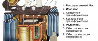
The characteristics of the presented equipment indicate the presence of a list of necessary structural elements. Passport data reveals information about the composition of the system. It includes a welded tank with a lid and an active part. The body has an oval configuration. There are LV and HV terminals on the cover. TM transformers include a switch, an expander with an oil level indicator, and an air drying device.
The active part includes a magnetic drive with winding contours. The core has upper and lower beams. Oil transformers have a switch installed. It controls the tap windings. The contours have a cylindrical configuration. The core is made of special ferromagnetic steel, and the circuits are made of copper.
The operating instructions provide for the convenience of installing equipment, the weight of which in some cases exceeds 4 thousand kg, two hooks on top of the tank. There is a grounding plate and a plug at the bottom that allows you to drain the oily substance from the system. The description of this design suggests the possibility of taking samples of the cooler. Dimensional units are firmly installed on the prepared surface. For this purpose, plates with holes for mounting on the foundation are installed in the lower part. This procedure is specified in the passport data.
Numbers
The listed designations may be followed by numerical values. This is the rated winding voltage in kV, power in kVA. For autotransformers, information about the voltage of the MV winding is added.
The marking may contain the first year of manufacture of the presented design. The power of the units can be 20.40, 63, 160, 630, 1600 kVA, etc. This indicator is selected in accordance with the operating conditions. Higher power equipment is available. This parameter can reach 200, 500 MVA.
The duration of use of Soviet-made transformers is about 50 years. Therefore, modern energy communications can use equipment manufactured before 1968. They are periodically improved and reconstructed during major overhauls.
TCM transcript
These electromagnetic devices are designed for three-phase circuits and are made without additional cooling, that is, dry. Their power ranges from 0.16 to 1 kVA, most often used for rectifiers and semiconductor power supplies. One of the advantages of such a device is that it can be located in the housing in any position, horizontal or vertical.
The decoding of its markings is as follows:
After which its power and additional conditions of climatic use are indicated.
In industry and in everyday life, many dry and oil-based transformers for various purposes are used. If there is a factory plate on them, then deciphering it is not difficult. The main thing is to apply it in accordance with the type of electrical installation, power, and also that the voltages and currents of all windings are used under normal conditions without overloads. Then these unpretentious, reliable and low-maintenance devices can last for decades.
Examples
To understand how to interpret the information on the equipment body, you should consider several examples of markings. These can be the following transformers:
- TDTN-1600/110. Three-phase class of step-down type equipment. It has oil forced cooling and an on-load tap-changer. The rated power is 1600, and the HV winding voltage is 110 kV.
- ATDTsTN-120000/500/110-85. Autotransformer, which is used in a three-phase network. It has three windings. The oil cooling system has forced circulation. There is an on-load tap-changer. The rated power is 120 MVA. The device reduces voltage and operates between 500 and 110 kV networks. Developed in 1985.
- TM-100/10 is a two-winding unit that is designed to operate in a three-phase network. The oil circulation system has natural fluid movement. The voltage change occurs using the PBB unit. The rated power is 100 kVA, and the winding class is 10 kV.
- TRDNS-25000/35-80. Device for a three-phase network with two split windings. Cooling is carried out through forced oil circulation. The design includes an on-load tap-changer regulator. Used for the needs of power plants. The power of the unit is 25 MVA. Winding voltage class – 35 kV. The design was developed in 1980.
- OTs-350000/500. Two-winding device for a single-phase upgrading network. Oil cooling is used using forced fluid movement. Power 350 MVA, winding voltage 500 kV.
- TSZ-250/10-79. An instance for a three-phase network with a dry cooling method. The case is protected. The power is 250 kVA, and the windings are 10 kV. The device was created in 1979.
- TDTSTGA-350000/500/110-60. Three-winding device for three-phase network. Used to increase voltage. Transformation occurs according to the principle of NN-CH and NN-VN. The design was developed in 1960.
Marking of transformers - current, voltage and power
To understand for what operating conditions a particular current or voltage transformer, as well as other types, is intended, special markings of devices are used. Domestic and imported units have different designations. In our country, installations manufactured in accordance with GOST are more often used.
Transformers are marked on a metal shield on the housing. The most common types of transformer symbols will be discussed below.
Information on the case
The information presented on the visible side of the device is applied using engraving, etching or embossing. This ensures the clarity and durability of the inscription. The metal plate contains information about the equipment manufacturer. The year of its manufacture and serial number are applied.
In addition to information about the manufacturer, there must be information about the unit. The number of the standard to which the presented design corresponds is indicated. The rated power indicator must be indicated. For three-phase devices, this parameter is given for each winding separately. Information about the voltage of the coil turns branches is indicated.
The rated current is determined for all windings. The number of installation phases and current frequency are given. The manufacturer provides data on the configuration and connection groups of the coils.
After the above information, you can familiarize yourself with the short circuit voltage parameters. Installation requirements are provided. It can be external or internal.
Technical characteristics allow you to determine the cooling method, the mass of oil in the tank (if this system is used), as well as the mass of the active part. The switch actuator indicates its position. If the installation has a dry type of cooling, there is data on the power of the installation when the fan is turned off.
The serial number must be stamped under the shield. It is present on the tank. The number is indicated on the cover near the HV input, as well as on the top and left on the core beam flange.
Scheme
All data shown on the plate can be divided into 6 groups. In order not to get confused in the information, you should consider the sequence of its writing. For example, installation ATDTsTN-125000/220/110/10-U 1. The following groups are used to mark the features of the device:
- Group I. A - Designed to indicate the type of device (power or autotransformer).
- Group II. T - Corresponds to the type of network for which the device is used (single-phase, three-phase).
- III group. DC – Cooling system with forced circulation of oil and air.
- IV group. T – Shows the number of windings (three-winding).
- V group. N – Voltage is regulated under load.
- VI group. All numbers (rated power, voltage of HV MV windings, climatic version, placement category).
You should learn more about each category. This will make the choice much easier.
Varieties
The designation of transformers necessarily begins with the type of equipment. If the marking begins with the letter A, it is an autotransformer. Its absence indicates that the unit belongs to the class of power transformers.
The number of phases is required. This allows you to choose an installation operating from a household or industrial network. If the transformer is connected to a three-phase network, the marking will contain a T. Single-phase varieties have the letter O. They are used in household networks.
If the device has a split winding, it will have a P. If there is on-load voltage regulation (OLTC), the device will be marked H on the metal plate. If it is absent, we can conclude that the presented feature is absent in the device.
Special designations
Depending on the installation category, special symbols may apply. For a current and voltage transformer, they may not be the same. The second type of technique is used when operating protective mechanisms or for measuring current. The first category of devices is intended to change the value of alternating current.
Voltage transformers do not use high power transmission of electricity. They are capable of creating isolation from low-voltage communications. This category of devices is used in circuits with a voltage of 12V or less. Their main operating parameters are the current and voltage of the primary winding. It is their value that is provided by the manufacturer.
The marking of voltage transformers begins with their design. If this is a walk-through structure, it is designated by the letter P. If it is not there, this is a supporting type of apparatus. The cast insulator is marked L, and the porcelain insulator is marked F. The built-in insulator is marked V.
Decoding of modern current transformers is carried out in the established sequence. It begins with T, which characterizes the devices presented. The installation method can be through-type (P), support (O) or busbar (W). If this device is present in the equipment of power transformers, it is designated as VT. If it is built into the oil switch, then the marking will have the letter B. When installed externally, the device will have an H.
Cooling system
The transformer symbol continues with the cooling method. Today, there are dry, oil-based varieties. Also, the cooling unit may contain a non-flammable fluid dielectric.
Oil varieties include about a dozen different equipment designs. If the circulation of liquid inside is carried out naturally, the device has an M on the panel. If it is forced, the designation D will be present here. It also corresponds to dry varieties of devices with an internal circulation device presented.
If equipment with natural oil movement and forced water flow is installed, it is marked with the combination MV. For devices with forced circulation of non-directional oil flow and natural air movement, a combination of MCs is used. If in such a device the direction of the oil is clearly indicated, the marking will be NMC.
For systems with forced non-directional movement of oil and air, the designation DC is used, and for directional movement - NDC. When the oil moves in the space between the pipes and partitions through which water flows, such a unit has the letter C on the shield. If the oil flows along a directed vector, the device is marked NC.
Cooling system with liquid dielectric
Today, new types of devices with various improved cooling systems are being put into operation. One of them is equipment with a non-flammable liquid dielectric. If cooling occurs through natural circulation, the presented installation is designated by the letter N. If there is forced air movement, the marking will be ND.
On the plate of units with a directed flow of liquid dielectric and forced air circulation, the NND is indicated. This allows you to choose the right type of equipment.
Dry systems
One of the new varieties is dry cooling systems. They are easy to operate and maintain, not demanding and not capricious. If the installation is open and air circulation occurs naturally, it is marked as C.
The protected version is designated by the letters SZ. The housing can be closed from the influence of various environmental factors; it is called hermetically sealed. With natural air circulation in it, the marking has the letters SG.
Air cooling systems may have forced circulation. In this case, the device is designated by the letters SD.
Execution
Installations may differ from each other in their design features. If they have forced water circulation, the letter B on the body will make it clear. If there is protection against thunderstorms and lightning, the design is marked G.
The system may have natural circulation of oil or non-flammable dielectric. At the same time, in some varieties protection with a nitrogen cushion is used. It does not have expanders or leads in the flanges of the tank walls. The designation has the letter Z.
Cast insulation is designated as L. The suspended version is designated by the letter P. The improved category of devices is designated as U. They may have automatic on-load tap-changers.
Equipment with leads and an expander installed on the flanges of the tank walls is marked with the letter F. An energy-saving device has reduced energy losses at idle. It is designated by the letter E.
Purpose
After the category of performance features, information about the purpose and scope of the equipment is presented. Marking with the letter B indicates the ability of the structure to warm up the soil or concrete in winter. A transformer intended for drilling rigs may have the same designation.
When electrifying the railway, installations with special properties and characteristics are needed. They are marked with the letter Z. Devices with the designation M are used at metallurgical plants.
When transmitting direct current through a line, class P structures are needed. Units for ensuring the operation of submersible pumps are designated as PN.
If the unit is used for the power plant’s own needs, it belongs to category C. Type TO is used for processing soil and concrete at high temperatures, providing electricity for temporary lighting and hand tools.
In coal mines transformers of the Sh variety are used, and in the electrical power supply system of an excavator - E.
Numbers
The listed designations may be followed by numerical values. This is the rated winding voltage in kV, power in kVA. For autotransformers, information about the voltage of the MV winding is added.
The marking may contain the first year of manufacture of the presented design. The power of the units can be 20.40, 63, 160, 630, 1600 kVA, etc. This indicator is selected in accordance with the operating conditions. Higher power equipment is available. This parameter can reach 200, 500 MVA.
The duration of use of Soviet-made transformers is about 50 years. Therefore, modern energy communications can use equipment manufactured before 1968. They are periodically improved and reconstructed during major overhauls.
Examples
To understand how to interpret the information on the equipment body, you should consider several examples of markings. These can be the following transformers:
- TDTN-1600/110. Three-phase class of step-down type equipment. It has oil forced cooling and an on-load tap-changer. The rated power is 1600, and the HV winding voltage is 110 kV.
- ATDTsTN-120000/500/110-85. Autotransformer, which is used in a three-phase network. It has three windings. The oil cooling system has forced circulation. There is an on-load tap-changer. The rated power is 120 MVA. The device reduces voltage and operates between 500 and 110 kV networks. Developed in 1985.
- TM-100/10 is a two-winding unit that is designed to operate in a three-phase network. The oil circulation system has natural fluid movement. The voltage change occurs using the PBB unit. The rated power is 100 kVA, and the winding class is 10 kV.
- TRDNS-25000/35-80. Device for a three-phase network with two split windings. Cooling is carried out through forced oil circulation. The design includes an on-load tap-changer regulator. Used for the needs of power plants. The power of the unit is 25 MVA. Winding voltage class – 35 kV. The design was developed in 1980.
- OTs-350000/500. Two-winding device for a single-phase upgrading network. Oil cooling is used using forced fluid movement. Power 350 MVA, winding voltage 500 kV.
- TSZ-250/10-79. An instance for a three-phase network with a dry cooling method. The case is protected. The power is 250 kVA, and the windings are 10 kV. The device was created in 1979.
- TDTSTGA-350000/500/110-60. Three-winding device for three-phase network. Used to increase voltage. Transformation occurs according to the principle of NN-CH and NN-VN. The design was developed in 1960.
Video: Classification of transformers
Having considered the marking features of various types of transformers, you can correctly use them at the site. Knowledge of the designations allows you to understand the functions and main technical characteristics of such equipment. The marking, which includes letters and numbers, complies with GOST standards used in the manufacturing process of special equipment.
